
User Manual
Page 1
P5P41T LE Motherboard
P5P41T LE Motherboard
User Manual
Page 3
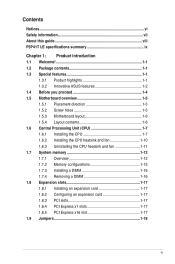
Contents Notices...vi Safety information vii About this guide viii P5P41T LE specifications summary ix Chapter 1: Product introduction 1.1 Welcome 1-1 1.2 Package contents 1-1 1.3 Special features 1-1 1.3.1 Product highlights 1-1 1.3.2 Innovative ASUS features 1-2 1.4 Before you proceed 1-4 1.5 Motherboard overview 1-5 1.5.1 Placement direction 1-5 1.5.2 Screw holes 1-5 1.5.3 Motherboard layout 1-6 1.5.4 Layout contents 1-6 1.6 Central Processing Unit (CPU 1-7 1.6.1 Installing the CPU 1-7 1.6.2 Installing the CPU heatsink and fan 1-10 1.6.3 Uninstalling...
Contents Notices...vi Safety information vii About this guide viii P5P41T LE specifications summary ix Chapter 1: Product introduction 1.1 Welcome 1-1 1.2 Package contents 1-1 1.3 Special features 1-1 1.3.1 Product highlights 1-1 1.3.2 Innovative ASUS features 1-2 1.4 Before you proceed 1-4 1.5 Motherboard overview 1-5 1.5.1 Placement direction 1-5 1.5.2 Screw holes 1-5 1.5.3 Motherboard layout 1-6 1.5.4 Layout contents 1-6 1.6 Central Processing Unit (CPU 1-7 1.6.1 Installing the CPU 1-7 1.6.2 Installing the CPU heatsink and fan 1-10 1.6.3 Uninstalling...
User Manual
Page 8
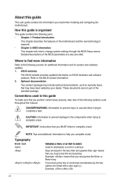
... NOTE: Tips and additional information to help you need when installing and configuring the motherboard. Example: ++ viii ASUS websites The ASUS website provides updated information on ASUS hardware and software products. IMPORTANT: Instructions that may have been added by your dealer... when trying to the ASUS contact information. 2. Example: means that you must press the enclosed key. Detailed descriptions of the motherboard and the new technology it �e�m�t�o�s�e�le�c�t. Typography Bold...
... NOTE: Tips and additional information to help you need when installing and configuring the motherboard. Example: ++ viii ASUS websites The ASUS website provides updated information on ASUS hardware and software products. IMPORTANT: Instructions that may have been added by your dealer... when trying to the ASUS contact information. 2. Example: means that you must press the enclosed key. Detailed descriptions of the motherboard and the new technology it �e�m�t�o�s�e�le�c�t. Typography Bold...

User Manual
Page 11
...™ 2 Duo processors, which are excellent for multitasking, multimedia, and enthusiastic gamers with the list below. 1.2 Package contents Check your motherboard package for buying an ASUS® P5P41T LE motherboard! Chapter 1 Product introduction 1.1 Welcome! This motherboard also supports Intel® CPUs in the long line of the above items is damaged or missing, contact your package...
...™ 2 Duo processors, which are excellent for multitasking, multimedia, and enthusiastic gamers with the list below. 1.2 Package contents Check your motherboard package for buying an ASUS® P5P41T LE motherboard! Chapter 1 Product introduction 1.1 Welcome! This motherboard also supports Intel® CPUs in the long line of the above items is damaged or missing, contact your package...

User Manual
Page 13
.... This is subject to convert your favorite photo into a 256-color boot logo for Express Gate source codes. ASUS AI NET2 ASUS AI NET2 remotely detects the cable connection immediately after turning on the use of creating environment-friendly and recyclable products/...Green ASUS This motherboard and its packaging comply with the ASUS vision of Hazardous Substances (RoHS). eliminates the need to 100 meters at 1 meter accuracy. If overclocking failed, press the power button to http://support.asus.com for a more colorful and vivid image on the environment. ASUS P5P41T LE ...
.... This is subject to convert your favorite photo into a 256-color boot logo for Express Gate source codes. ASUS AI NET2 ASUS AI NET2 remotely detects the cable connection immediately after turning on the use of creating environment-friendly and recyclable products/...Green ASUS This motherboard and its packaging comply with the ASUS vision of Hazardous Substances (RoHS). eliminates the need to 100 meters at 1 meter accuracy. If overclocking failed, press the power button to http://support.asus.com for a more colorful and vivid image on the environment. ASUS P5P41T LE ...
User Manual
Page 14
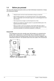
... you must shut down the system and unplug the power cable before you install motherboard components or change any motherboard settings. • Unplug the power cord from the power supply. P5P41T LE SB_PWR ON OFF Standby Power Powered Off P5P41T LE Onboard LED 1-4 Chapter 1: Product introduction 1.4 Before you proceed Take note of ...that the system is ON, in sleep mode, or in the bag that came with a standby power LED that lights up to the motherboard, peripherals, or components. Onboard LED The motherboard comes with the component. • Before you install or remove any...
... you must shut down the system and unplug the power cable before you install motherboard components or change any motherboard settings. • Unplug the power cord from the power supply. P5P41T LE SB_PWR ON OFF Standby Power Powered Off P5P41T LE Onboard LED 1-4 Chapter 1: Product introduction 1.4 Before you proceed Take note of ...that the system is ON, in sleep mode, or in the bag that came with a standby power LED that lights up to the motherboard, peripherals, or components. Onboard LED The motherboard comes with the component. • Before you install or remove any...
User Manual
Page 15
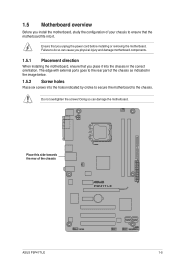
... you place it . 1.5 Motherboard overview Before you install the motherboard, study the configuration of your chassis to ensure that the motherboard fits into it into the holes indicated by circles to secure the motherboard to the chassis. The edge with external ports goes to the rear part of the chassis P5P41T LE ASUS P5P41T LE 1-5 Ensure that you unplug...
... you place it . 1.5 Motherboard overview Before you install the motherboard, study the configuration of your chassis to ensure that the motherboard fits into it into the holes indicated by circles to secure the motherboard to the chassis. The edge with external ports goes to the rear part of the chassis P5P41T LE ASUS P5P41T LE 1-5 Ensure that you unplug...
User Manual
Page 16
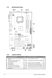
...Speaker connector (4- Clear RTC RAM (3-pin CLRTC) 1-18 ATX12V) 2. pin SPEAKER) 1-22 4. Digital audio connector (4-1 pin SPDIF_OUT) 1-20 6. 1.5.3 Motherboard layout KBMS 12 3 18.3cm(7.2in) 24 CPU_FAN ATX12V COM1 LPT DDR3 DIMM_A1 (64bit, 240-pin module) DDR3 DIMM_B1 (64bit, 240-pin module) USB34... LGA775 PRI_IDE 5 30.5cm(12.0in) LAN1_USB12 CHA_FAN Intel® G41 AUDIO ICS 9LRS954 1 EATXPWR ATHEROS AR8121 PCIEX1_1 P5P41T LE PCIEX16_1 Super I/O PCIEX1_2 Lithium Cell CMOS Power ALC 662 AAFP SPDIF_OUT 13 12 PCI1 PCI2 PCI3 Intel® ICH7 SATA1 SATA2 ...
...Speaker connector (4- Clear RTC RAM (3-pin CLRTC) 1-18 ATX12V) 2. pin SPEAKER) 1-22 4. Digital audio connector (4-1 pin SPDIF_OUT) 1-20 6. 1.5.3 Motherboard layout KBMS 12 3 18.3cm(7.2in) 24 CPU_FAN ATX12V COM1 LPT DDR3 DIMM_A1 (64bit, 240-pin module) DDR3 DIMM_B1 (64bit, 240-pin module) USB34... LGA775 PRI_IDE 5 30.5cm(12.0in) LAN1_USB12 CHA_FAN Intel® G41 AUDIO ICS 9LRS954 1 EATXPWR ATHEROS AR8121 PCIEX1_1 P5P41T LE PCIEX16_1 Super I/O PCIEX1_2 Lithium Cell CMOS Power ALC 662 AAFP SPDIF_OUT 13 12 PCI1 PCI2 PCI3 Intel® ICH7 SATA1 SATA2 ...
User Manual
Page 17
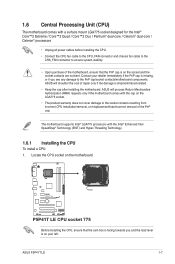
... cap is shipment/transit-related. • Keep the cap after installing the motherboard. The motherboard supports Intel® LGA775 processors with the Intel® Enhanced Intel SpeedStep® Technology (EIST) and Hyper-Threading Technology. 1.6.1 Installing the CPU To install a CPU: 1. ASUS P5P41T LE 1-7 P5P41T LE P5P41T LE CPU socket 775 Before installing the CPU, ensure that the PnP cap...
... cap is shipment/transit-related. • Keep the cap after installing the motherboard. The motherboard supports Intel® LGA775 processors with the Intel® Enhanced Intel SpeedStep® Technology (EIST) and Hyper-Threading Technology. 1.6.1 Installing the CPU To install a CPU: 1. ASUS P5P41T LE 1-7 P5P41T LE P5P41T LE CPU socket 775 Before installing the CPU, ensure that the PnP cap...

User Manual
Page 21
... B A B B A B A ASUS P5P41T LE 1-11 Hardware monitoring errors can occur if you fail to connect the CPU fan connector! Disconnect the CPU fan cable from the motherboard. Pull up two fasteners at a time in a diagonal sequence to the connector on the motherboard. 2. Rotate each fastener counterclockwise. 3. ...CPU_FAN CPU FAN PWM CPU FAN IN CPU FAN PWR GND P5P41T LE P5P41T LE CPU fan connector Do not forget to plug this connector. 1.6.3 Uninstalling the...
... B A B B A B A ASUS P5P41T LE 1-11 Hardware monitoring errors can occur if you fail to connect the CPU fan connector! Disconnect the CPU fan cable from the motherboard. Pull up two fasteners at a time in a diagonal sequence to the connector on the motherboard. 2. Rotate each fastener counterclockwise. 3. ...CPU_FAN CPU FAN PWM CPU FAN IN CPU FAN PWR GND P5P41T LE P5P41T LE CPU fan connector Do not forget to plug this connector. 1.6.3 Uninstalling the...
User Manual
Page 22
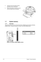
4. The figure illustrates the location of the DDR3 DIMM sockets: DIMM_A1 DIMM_B1 P5P41T LE Channel Channel A Channel B Sockets DIMM_A1 DIMM_B1 P5P41T LE 240-pin DDR3 DIMM sockets 1-12 Chapter 1: Product introduction Rotate each fastener clockwise to ensure correct orientation when reinstalling. 1.7 System memory 1.7.1 Overview The motherboard comes with two Double Data Rate 3 (DDR3) Dual Inline Memory Modules (DIMM) sockets. Carefully remove the heatsink and fan assembly from the motherboard. 5.
4. The figure illustrates the location of the DDR3 DIMM sockets: DIMM_A1 DIMM_B1 P5P41T LE Channel Channel A Channel B Sockets DIMM_A1 DIMM_B1 P5P41T LE 240-pin DDR3 DIMM sockets 1-12 Chapter 1: Product introduction Rotate each fastener clockwise to ensure correct orientation when reinstalling. 1.7 System memory 1.7.1 Overview The motherboard comes with two Double Data Rate 3 (DDR3) Dual Inline Memory Modules (DIMM) sockets. Carefully remove the heatsink and fan assembly from the motherboard. 5.

User Manual
Page 23
...P5P41T LE Motherboard Qualified Vendors Lists (QVL) DDR3-1333 MHz capability Vendor Part No. Install a 64-bit �W�i�nd�o�w��s® OS when you want to install 4GB or more memory on the motherboard. • This motherboard does not support DIMMs made up of 3 ) DS Micron 8UD22D9JNM (continued on the motherboard... 7-7-7-24 9 Voltage 1.65-1.85V 1.65-1.85V 1.60V 1.5V 1.8V 1.8V 1.8V 1.65V DIMM Support A* B ASUS P5P41T LE 1-13 Size SS/ DS Brand Chip NO. 1.7.2 Memory configurations You may operate at a lower frequency than the vendor-...
...P5P41T LE Motherboard Qualified Vendors Lists (QVL) DDR3-1333 MHz capability Vendor Part No. Install a 64-bit �W�i�nd�o�w��s® OS when you want to install 4GB or more memory on the motherboard. • This motherboard does not support DIMMs made up of 3 ) DS Micron 8UD22D9JNM (continued on the motherboard... 7-7-7-24 9 Voltage 1.65-1.85V 1.65-1.85V 1.60V 1.5V 1.8V 1.8V 1.8V 1.65V DIMM Support A* B ASUS P5P41T LE 1-13 Size SS/ DS Brand Chip NO. 1.7.2 Memory configurations You may operate at a lower frequency than the vendor-...
User Manual
Page 27
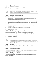
... 3. Unplug the power cord before adding or removing expansion cards. Remove the bracket opposite the slot that you physical injury and damage motherboard components. 1.8.1 Installing an expansion card To install an expansion card: 1. Keep the screw for the card. 2. Install the software ...settings. 1. Secure the card to the chassis with the PCI Express specifications. Failure to do not need to install expansion cards. ASUS P5P41T LE 1-17 Replace the system cover. 1.8.2 Configuring an expansion card After installing the expansion card, configure it and make the necessary hardware...
... 3. Unplug the power cord before adding or removing expansion cards. Remove the bracket opposite the slot that you physical injury and damage motherboard components. 1.8.1 Installing an expansion card To install an expansion card: 1. Keep the screw for the card. 2. Install the software ...settings. 1. Secure the card to the chassis with the PCI Express specifications. Failure to do not need to install expansion cards. ASUS P5P41T LE 1-17 Replace the system cover. 1.8.2 Configuring an expansion card After installing the expansion card, configure it and make the necessary hardware...

User Manual
Page 30
...the system may damage the motherboard components. Do not forget to connect the fan cables to a slot opening at +12V. CPU_FAN CPU FAN PWM CPU FAN IN CPU FAN PWR GND P5P41T LE CHA_FAN GND +12V Rotation P5P41T LE fan connectors Only the 4-pin CPU fan connector supports the ASUS Q-FAN feature. 2. 1.10... connectors! Do not place jumper caps on the motherboard, ensuring that the black wire of each cable matches the ground pin of 1A~2.22A (26.64W max.) at the back of the system chassis. +5V SPDIFOUT GND P5P41T LE SPDIF_OUT P5P41T LE Digital audio connector The S/PDIF module is for ...
...the system may damage the motherboard components. Do not forget to connect the fan cables to a slot opening at +12V. CPU_FAN CPU FAN PWM CPU FAN IN CPU FAN PWR GND P5P41T LE CHA_FAN GND +12V Rotation P5P41T LE fan connectors Only the 4-pin CPU fan connector supports the ASUS Q-FAN feature. 2. 1.10... connectors! Do not place jumper caps on the motherboard, ensuring that the black wire of each cable matches the ground pin of 1A~2.22A (26.64W max.) at the back of the system chassis. +5V SPDIFOUT GND P5P41T LE SPDIF_OUT P5P41T LE Digital audio connector The S/PDIF module is for ...
User Manual
Page 32
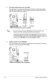
... end of the front panel audio I /O module that you connect a high-definition front panel audio module to this connector to avail of the motherboard's high-definition audio capability. • If you want to connect a high-definition front panel audio module to this connector is set the item...6. By default, this connector, set the Front Panel Type item in the BIOS setup to [AC97]. 5. GND PRESENCE# SENSE1_RETUR SENSE2_RETUR AGND NC NC NC P5P41T LE AAFP PIN 1 PIN 1 MIC2 MICPWR Line out_R NC Line out_L PORT1 L PORT1 R PORT2 R SENSE_SEND PORT2 L HD-audio-compliant Legacy AC'97 pin...
... end of the front panel audio I /O module that you connect a high-definition front panel audio module to this connector to avail of the motherboard's high-definition audio capability. • If you want to connect a high-definition front panel audio module to this connector is set the item...6. By default, this connector, set the Front Panel Type item in the BIOS setup to [AC97]. 5. GND PRESENCE# SENSE1_RETUR SENSE2_RETUR AGND NC NC NC P5P41T LE AAFP PIN 1 PIN 1 MIC2 MICPWR Line out_R NC Line out_L PORT1 L PORT1 R PORT2 R SENSE_SEND PORT2 L HD-audio-compliant Legacy AC'97 pin...

User Manual
Page 33
... IDE ribbon cable to match the covered hole on each Ultra DMA 100/66/33 signal cable: blue, black, and gray. 7. ASUS P5P41T LE 1-23 Connect the blue connector to the motherboard's IDE connector, then select one of device(s) Master Slave Master Slave Cable connector Black Black Gray Black or gray • Pin 20... prevents incorrect insertion when you connect the IDE cable. • Use the 80-conductor IDE cable for the Ultra DMA 100/66/33 signal cable. P5P41T LE IDE connector If any device jumper is removed to PIN 1.
... IDE ribbon cable to match the covered hole on each Ultra DMA 100/66/33 signal cable: blue, black, and gray. 7. ASUS P5P41T LE 1-23 Connect the blue connector to the motherboard's IDE connector, then select one of device(s) Master Slave Master Slave Cable connector Black Black Gray Black or gray • Pin 20... prevents incorrect insertion when you connect the IDE cable. • Use the 80-conductor IDE cable for the Ultra DMA 100/66/33 signal cable. P5P41T LE IDE connector If any device jumper is removed to PIN 1.

User Manual
Page 35
....0 connectors Never connect a 1394 cable to a slot opening at the back of the system chassis. ASUS P5P41T LE 1-25 These USB connectors comply with USB 2.0 specification that supports up to 480 Mbps connection speed. Doing so will damage the motherboard! USB connectors (10-1 pin USB56, USB78) These connectors are for USB 2.0 ports. 9. The USB...
....0 connectors Never connect a 1394 cable to a slot opening at the back of the system chassis. ASUS P5P41T LE 1-25 These USB connectors comply with USB 2.0 specification that supports up to 480 Mbps connection speed. Doing so will damage the motherboard! USB connectors (10-1 pin USB56, USB78) These connectors are for USB 2.0 ports. 9. The USB...
User Manual
Page 37
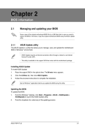
... through a network or an Internet Service Provider (ISP). • This utility is available in the support DVD that comes with the motherboard package. Chapter 2 BIOS information 2.1 Managing and updating your BIOS Save a copy of the updating process: ASUS P5P41T LE 2-1 Copy the original motherboard BIOS using this utility. Follow the onscreen instructions to launch the...
... through a network or an Internet Service Provider (ISP). • This utility is available in the support DVD that comes with the motherboard package. Chapter 2 BIOS information 2.1 Managing and updating your BIOS Save a copy of the updating process: ASUS P5P41T LE 2-1 Copy the original motherboard BIOS using this utility. Follow the onscreen instructions to launch the...

User Manual
Page 39
You can restore a corrupted BIOS file using the motherboard support DVD or a removable device that allows you to prevent system boot failure! 2.1.3 ASUS CrashFree BIOS The ASUS CrashFree BIOS is an auto recovery tool that contains the updated BIOS file. •...motherboard models. Insert the support DVD to the floppy disk drive, if supported. 3. The utility automatically checks the devices for details. Refer to ensure system compatibility and stability. When the correct BIOS file is found , the utility reads the BIOS file and starts flashing the corrupted BIOS file. 4. ASUS P5P41T LE...
You can restore a corrupted BIOS file using the motherboard support DVD or a removable device that allows you to prevent system boot failure! 2.1.3 ASUS CrashFree BIOS The ASUS CrashFree BIOS is an auto recovery tool that contains the updated BIOS file. •...motherboard models. Insert the support DVD to the floppy disk drive, if supported. 3. The utility automatically checks the devices for details. Refer to ensure system compatibility and stability. When the correct BIOS file is found , the utility reads the BIOS file and starts flashing the corrupted BIOS file. 4. ASUS P5P41T LE...


