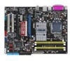
P5ne-sli - Asus P5N E SLI Motherboard ATX
Related Manual Pages


Related Videos

Asus P5N-E SLI Motherboard
Duration: 5:32
Total Views: 101,004
Duration: 5:32
Total Views: 101,004
BOARD ASUS P5N E SLI Memorias OCZ DDR2 800 REAPER 4GB
Duration: 1:41
Total Views: 1,051
Duration: 1:41
Total Views: 1,051
Asus p5n-e sli. death :(
Duration: 1:04
Total Views: 490
Duration: 1:04
Total Views: 490
Prueba de Overclock en P5N-E SLI
Duration: 1:05
Total Views: 77
Duration: 1:05
Total Views: 77
Usando Placa Mãe P5N-E SLI do "Kite"
Duration: 1:01
Total Views: 181
Duration: 1:01
Total Views: 181
Similar Questions

I Have The Rare L1n64-sli Ws Tech Demo Unit
I need to find a way to force my L1n64-SLI WS over to the /B bios so I can run my pair of 2347 HE Op...
I need to find a way to force my L1n64-SLI WS over to the /B bios so I can run my pair of 2347 HE Op...
(Posted by wrenchmadison 7 years ago)

Sli
computer won't start with 2 980 gtx strix card in sli with bridge connector all power leads connecte...
computer won't start with 2 980 gtx strix card in sli with bridge connector all power leads connecte...
(Posted by spandexhead 7 years ago)

Related Terms
The following terms were also used when searching for P5ne-sli - Asus P5N E SLI Motherboard ATX:- asus p5n e sli
- asus p5n-e sli
- asus p5n e
- asus p5n em
- asus p5n e sli motherboard
- asus p5n em hdmi
- p5n e sli motherboard
- p5n-e sli motherboard
- asus p5n e sli nforce 650i
- asus p5n e sli bios
- asus p5n e sli drivers
- p5n-e sli bios
- asus p5n e bios
- p5n e sli asus
- p5n-e bios
- p5n-e sli memory
- p5n e sli nforce 650i
- p5n em-hdmi
- p5n-e sli drivers
- asus p5n e nforce 650i
- p5n sli motherboard
- asus p5n em-hdmi
- p5n e nforce 650i
- asus p5n-e bios
- asus p5n-e sli bios
- asus p5n-e sli drivers
- p5n e motherboard
- p5n e sli bios update
- p5ne sli overclock
- p5n-e sli cpu
- p5ne sli bios
- asus p5n-e sli memory
- asus p5n e motherboard
- asus p5ne sli motherboard
- p5n-e sli raid
- p5nesli drivers
- p5ne sli drivers
- asus p5n e sli manual
- asus p5ne sli bios
- asus p5ne sli memory
- p5ne sli motherboard
- asus p5n e sli bios update
- overclocking p5n e sli
- p5ne sli cpu
- p5n-e drivers
- p5n-e sli manual
- asus p5n-e drivers
- p5n e drivers
- p5n e sli lan driver
- p5n-e sli asus
- p5n e manual
- p5n e sli vista driver
- p5ne sli manual
- p5ne sli raid
- asus p5n e sli lan driver
- asus p5n-e sli manual
- asus p5ne sli socket 775 motherboard
- p5n e sli motherboard manual
- p5ne sli ram
- p5nesli overclock
- asus p5n e drivers
- asus p5n e manual
- asus p5n e sli motherboard manual
- asus p5ne sli 650i
- p5n e sli drivers windows 7
- p5n-e sli bios update
- ahci asus p5n e sli
- ahci p5n e sli
- asus p5n e fail fail
- asus p5n e sli beep codes
- asus p5n e sli bios download
- asus p5n e sli boot from usb
- asus p5n e sli cd download
- asus p5n e sli clear cmos
- asus p5n e sli cpu support
- asus p5n e sli ddr3 compatible
- asus p5n e sli lga 775
- asus p5n e sli memory
- asus p5n e sli motherboard drivers
- asus p5n e sli network driver
- asus p5n e sli network drivers
- asus p5n e sli nforce 650i sli
- asus p5n e sli onboard graphics
- asus p5n e sli overclocking
- asus p5n e sli power supply
- asus p5n e sli ssd support
- asus p5n e sli troubleshooting
- asus p5n e sli usb 3.0
- asus p5n e sli usb boot
- asus p5n e sli video
- asus p5n e sli video card set
- asus p5n e sli windows 7 drivers
- asus p5n e-sli
- asus p5n e-sli bios update
- asus p5n e-sli drivers
- asus p5n e-sli manual
- asus p5n em hdmi motherboard
- asus p5n-e
- asus p5n-e 650i
- asus p5n-e bios update
- asus p5n-e manual
- asus p5n-e motherboard
- asus p5n-e nforce 650i
- asus p5n-e nforce 650i sli
- asus p5n-e sli atx
- asus p5n-e sli beep codes
- asus p5n-e sli bios flash
- asus p5n-e sli bios reset
- asus p5n-e sli bios update
- asus p5n-e sli boot from usb
- asus p5n-e sli cmos reset jumper
- asus p5n-e sli driver
- asus p5n-e sli drivers windows 7
- asus p5n-e sli drivers windows xp
- asus p5n-e sli front panel connections
- asus p5n-e sli graphics card compatibility
- asus p5n-e sli memory compatibility
- asus p5n-e sli motherboard
- asus p5n-e sli motherboard beep
- asus p5n-e sli motherboard bios update
- asus p5n-e sli motherboard drivers
- asus p5n-e sli motherboard manual
- asus p5n-e sli network driver
- asus p5n-e sli network drivers
- asus p5n-e sli nforce 650i
- asus p5n-e sli no post
- asus p5n-e sli no video
- asus p5n-e sli not booting
- asus p5n-e sli overclocking
- asus p5n-e sli pci express 3.0
- asus p5n-e sli power supply
- asus p5n-e sli processor compatibility
- asus p5n-e sli raid setup
- asus p5n-e sli ram
- asus p5n-e sli ram compatibility
- asus p5n-e sli sleep
- asus p5n-e sli video card
- asus p5n-e sli will not post
- asus p5n-e sli windows 10
- asus p5n-e sli windows 7 drivers
- asus p5n-em
- asus p5n-em hdmi
- asus p5n-em hdmi motherboard
- asus p5ne sli drivers
- asus p5ne sli manual
- asus p5ne sli overclock
- bios p5n e sli
- how to overclock p5ne sli
- p5n e asus
- p5n e bios
- p5n e fail fail
- p5n e sli
- p5n e sli .bin
- p5n e sli 650i
- p5n e sli ahci
- p5n e sli asus drivers
- p5n e sli beep codes
- p5n e sli bios
- p5n e sli bios download
- p5n e sli boot from usb
- p5n e sli cd download
- p5n e sli clear cmos
- p5n e sli cpu
- p5n e sli cpu list
- p5n e sli cpu support
- p5n e sli cpu support list
- p5n e sli crossfire
- p5n e sli ddr3 compatible
- p5n e sli drivers
- p5n e sli esata
- p5n e sli hackintosh
- p5n e sli manual
- p5n e sli memory
- p5n e sli motherboard diagram
- p5n e sli motherboard drivers
- p5n e sli network driver
- p5n e sli network drivers
- p5n e sli nforce 650i sli
- p5n e sli onboard graphics
- p5n e sli overclock
- p5n e sli overclock.net
- p5n e sli overclocking
- p5n e sli pci express 2.0
- p5n e sli power supply
- p5n e sli problems
- p5n e sli q6600
- p5n e sli q6600 overclock
- p5n e sli raid setup
- p5n e sli ram
- p5n e sli ram compatibility
- p5n e sli reset bios
- p5n e sli ssd support
- p5n e sli troubleshooting
- p5n e sli usb 3.0
- p5n e sli usb boot
- p5n e sli usb problem
- p5n e sli video
- p5n e sli video card set
- p5n e sli wake on lan
- p5n e sli windows 10
- p5n e sli windows 7
- p5n e sli windows 7 bios update
- p5n e sli windows 7 drivers
- p5n e sli.bin
- p5n e-sli
- p5n e-sli bios update
- p5n e-sli boot
- p5n e-sli drivers
- p5n e-sli manual
- p5n e-sli motherboard bios update
- p5n em hdmi
- p5n em hdmi motherboard
- p5n sli asus
- p5n-e 650i
- p5n-e asus
- p5n-e asus drivers
- p5n-e asus manual
- p5n-e bios update
- p5n-e manual
- p5n-e motherboard
- p5n-e nforce 650i
- p5n-e nforce 650i sli
- p5n-e sli
- p5n-e sli 1.xx
- p5n-e sli asus drivers
- p5n-e sli asus manual
- p5n-e sli atx
- p5n-e sli beep codes
- p5n-e sli bios flash
- p5n-e sli bios reset
- p5n-e sli bios update windows 7
- p5n-e sli boot from usb
- p5n-e sli chipset drivers
- p5n-e sli clear cmos
- p5n-e sli cmos reset jumper
- p5n-e sli cpu support
- p5n-e sli driver
- p5n-e sli driver download
- p5n-e sli drivers windows 7
- p5n-e sli drivers windows xp
- p5n-e sli front panel connections
- p5n-e sli graphic card compatibility
- p5n-e sli graphics card compatibility
- p5n-e sli hackintosh
- p5n-e sli jumpers
- p5n-e sli memory compatibility
- p5n-e sli memory support
- p5n-e sli motherboard beep
- p5n-e sli motherboard bios update
- p5n-e sli motherboard drivers
- p5n-e sli motherboard manual
- p5n-e sli network driver
- p5n-e sli network drivers
- p5n-e sli nforce 650i
- p5n-e sli no post
- p5n-e sli no power 4 pin
- p5n-e sli no video
- p5n-e sli not booting
- p5n-e sli overclock
- p5n-e sli overclocking
- p5n-e sli pci express 2.0
- p5n-e sli pci express 3.0
- p5n-e sli power supply
- p5n-e sli processor compatibility
- p5n-e sli processors
- p5n-e sli raid setup
- p5n-e sli ram
- p5n-e sli ram compatibility
- p5n-e sli replacement
- p5n-e sli sleep
- p5n-e sli socket
- p5n-e sli specifications
- p5n-e sli usb boot
- p5n-e sli video card
- p5n-e sli will not post
- p5n-e sli windows 10
- p5n-e sli windows 10 drivers
- p5n-e sli windows 7
- p5n-e sli windows 7 drivers
- p5n-e sli windows 8
- p5n-e sli windows 8 drivers
- p5n-e sli won't boot
- p5n-e-sli
- p5n-em hdmi
- p5n-em hdmi motherboard
- p5n-sli drivers
- p5ne sli .bin
- p5ne sli ahci
- p5ne sli asus com
- p5ne sli audio driver
- p5ne sli beep codes
- p5ne sli bios update
- p5ne sli chipset
- p5ne sli clear cmos
- p5ne sli cmos jumper
- p5ne sli cooling
- p5ne sli cpu support
- p5ne sli cpu support list
- p5ne sli driver
- p5ne sli drivers sata
- p5ne sli drivers windows 7
- p5ne sli esata
- p5ne sli front panel
- p5ne sli memory
- p5ne sli memory support
- p5ne sli network driver
- p5ne sli overclock voltage
- p5ne sli pci express 2.0
- p5ne sli q6600 overclock
- p5ne sli ram compatibility
- p5ne sli specifications
- p5ne sli ssd
- p5ne sli voltage adjust
- p5ne sli voltage control
- p5ne sli windows 10
- p5ne-sli
- p5ne-sli asus manual
- p5ne-sli asus manuale
- p5ne-sli beep codes
- p5ne-sli bios
- p5ne-sli bios update
- p5ne-sli cpu support
- p5ne-sli drivers
- p5ne-sli drivers asus
- p5ne-sli memory
- p5ne-sli motherboard
- p5nesli
- p5nesli asus
- p5nesli bios
- p5nesli esata
- p5nesli hackintosh
- p5nesli placa mae
- p5nesli.bin