
User Manual
Page 2
...is authorized in any form or by any means, except documentation kept by ASUS; ii Product warranty or service will not be registered trademarks or copyrights of alteration is defaced or missing. ASUS PROVIDES THIS MANUAL "AS IS" WITHOUT WARRANTY OF ANY KIND, EITHER EXPRESS OR IMPLIED, ...ADVISED OF THE POSSIBILITY OF SUCH DAMAGES ARISING FROM ANY DEFECT OR ERROR IN THIS MANUAL OR PRODUCT. or (2) the serial number of ASUSTeK COMPUTER INC. ("ASUS"). SPECIFICATIONS AND INFORMATION CONTAINED IN THIS MANUAL ARE FURNISHED FOR INFORMATIONAL USE ONLY, AND ARE SUBJECT TO CHANGE AT ANY TIME...
...is authorized in any form or by any means, except documentation kept by ASUS; ii Product warranty or service will not be registered trademarks or copyrights of alteration is defaced or missing. ASUS PROVIDES THIS MANUAL "AS IS" WITHOUT WARRANTY OF ANY KIND, EITHER EXPRESS OR IMPLIED, ...ADVISED OF THE POSSIBILITY OF SUCH DAMAGES ARISING FROM ANY DEFECT OR ERROR IN THIS MANUAL OR PRODUCT. or (2) the serial number of ASUSTeK COMPUTER INC. ("ASUS"). SPECIFICATIONS AND INFORMATION CONTAINED IN THIS MANUAL ARE FURNISHED FOR INFORMATIONAL USE ONLY, AND ARE SUBJECT TO CHANGE AT ANY TIME...

User Manual
Page 7
... service technician or your dealer immediately. • To avoid short circuits, keep paper clips, screws, and staples away from the motherboard, ensure that all the manuals that the power cables for the devices are unplugged before the signal cables are not damaged. vii If you are not sure about the voltage...
... service technician or your dealer immediately. • To avoid short circuits, keep paper clips, screws, and staples away from the motherboard, ensure that all the manuals that the power cables for the devices are unplugged before the signal cables are not damaged. vii If you are not sure about the voltage...
User Manual
Page 8
...this guide This user guide contains the information you have been added by your dealer. How this guide is organized This manual contains the following sources for additional information and for this motherboard. • Chapter 6: Driver installation This chapter provides information ... shutting down the system. • Chapter 4: BIOS setup Tells how to the ASUS contact information. 2. Where to find more information Refer to when configuring the motherboard. viii ASUS websites The ASUS website provides updated information on the motherboard. • Chapter 3: Powering up This ...
...this guide This user guide contains the information you have been added by your dealer. How this guide is organized This manual contains the following sources for additional information and for this motherboard. • Chapter 6: Driver installation This chapter provides information ... shutting down the system. • Chapter 4: BIOS setup Tells how to the ASUS contact information. 2. Where to find more information Refer to when configuring the motherboard. viii ASUS websites The ASUS website provides updated information on the motherboard. • Chapter 3: Powering up This ...

User Manual
Page 9
... or value enclosed in the less-than and greater-than sign means that you must press the Enter or Return key. Conventions used throughout this manual.
... or value enclosed in the less-than and greater-than sign means that you must press the Enter or Return key. Conventions used throughout this manual.

User Manual
Page 83
...Setting to [Auto] allows the BIOS to enable or disable the adjacent cache line prefetch feature. Select an item then press to manually set the DRAM frequency by SPD. Configuration options: [Disabled] [Enabled] 4.4.5 Chipset The Chipset menu allows you to enable or... Remap Feature [Auto] [Enabled] [Disabled] [Enabled] [TC7] [Disabled] [Disabled] Manual DRAM Frequency Setting or Auto by Serial Presence Detect (SPD). Adjacent Cache Line Prefetch [Enabled] Allows you to automatically set the DRAM frequency. Configuration options: [Auto] [533 MHz] [667 MHz] ASUS P5MT-M 4-23
...Setting to [Auto] allows the BIOS to enable or disable the adjacent cache line prefetch feature. Select an item then press to manually set the DRAM frequency by SPD. Configuration options: [Disabled] [Enabled] 4.4.5 Chipset The Chipset menu allows you to enable or... Remap Feature [Auto] [Enabled] [Disabled] [Enabled] [TC7] [Disabled] [Disabled] Manual DRAM Frequency Setting or Auto by Serial Presence Detect (SPD). Adjacent Cache Line Prefetch [Enabled] Allows you to automatically set the DRAM frequency. Configuration options: [Auto] [533 MHz] [667 MHz] ASUS P5MT-M 4-23

User Manual
Page 84
Configuration options: [2 Clocks] [3 Clocks] [4 Clocks] [5 Clocks] DRAM RAS# Activate to enable or disable the PCI Express Graphics port. When disabled, you can manually set the DRAM timing parameters through the DRAM sub-items. Configuration options: [Disabled] [Enabled] The following sub-items appear when this item is Disabled. Configuration ...
Configuration options: [2 Clocks] [3 Clocks] [4 Clocks] [5 Clocks] DRAM RAS# Activate to enable or disable the PCI Express Graphics port. When disabled, you can manually set the DRAM timing parameters through the DRAM sub-items. Configuration options: [Disabled] [Enabled] The following sub-items appear when this item is Disabled. Configuration ...
User Manual
Page 112
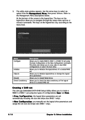
... the M a n a g e m e n t M e n u, then press . The keys on the legend box allow you to the menu level. Menu Configure Initialize Objects Rebuild Check Consistency Description Allows you manually set the logical drive parameters and assign the set using the Easy Configuration or the New Configuration command. 3. In E a s y C o n f i g u r a t i o n, the logical drive parameters are set...
... the M a n a g e m e n t M e n u, then press . The keys on the legend box allow you to the menu level. Menu Configure Initialize Objects Rebuild Check Consistency Description Allows you manually set the logical drive parameters and assign the set using the Easy Configuration or the New Configuration command. 3. In E a s y C o n f i g u r a t i o n, the logical drive parameters are set...
User Manual
Page 126
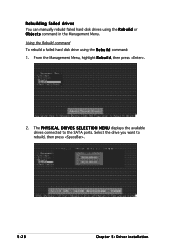
The P H Y S I C A L D R I V E S S E L E C T I O N M E N U displays the available drives connected to rebuild, then press . 5-28 Chapter 5: Driver installation Rebuilding failed drives You can manually rebuild failed hard disk drives using the R e b u i l d command: 1. Select the drive you want to the SATA ports. From the Management Menu, highlight R e b u i l d, then press . 2. Using the Rebuild command To rebuild a failed hard disk drive using the R e b u i l d or O b j e c t s command in the Management Menu.
The P H Y S I C A L D R I V E S S E L E C T I O N M E N U displays the available drives connected to rebuild, then press . 5-28 Chapter 5: Driver installation Rebuilding failed drives You can manually rebuild failed hard disk drives using the R e b u i l d command: 1. Select the drive you want to the SATA ports. From the Management Menu, highlight R e b u i l d, then press . 2. Using the Rebuild command To rebuild a failed hard disk drive using the R e b u i l d or O b j e c t s command in the Management Menu.
User Manual
Page 145
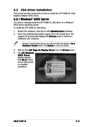
.... 4. Click N e x t. Insert the motherboard/system support CD to close this window. 3. Follow screen instructions to manually install the ATI® RAGE XL VGA driver on a Windows® 2000 Server operating system. The A T I W i n d o w s 2000 Driver window appears. ASUS P5MT-M 6-11 Restart the computer, then log on with A d m i n i s t r a t o r privileges. 2. Windows® automatically detects the LAN...
.... 4. Click N e x t. Insert the motherboard/system support CD to close this window. 3. Follow screen instructions to manually install the ATI® RAGE XL VGA driver on a Windows® 2000 Server operating system. The A T I W i n d o w s 2000 Driver window appears. ASUS P5MT-M 6-11 Restart the computer, then log on with A d m i n i s t r a t o r privileges. 2. Windows® automatically detects the LAN...


