
User Manual
Page 1
Motherboard P5KPL-AM/PS
Motherboard P5KPL-AM/PS
User Manual
Page 3
Contents Notices...vi Safety information vii About this guide vii P5KPL-AM/PS specifications summary ix Chapter 1: Product introduction 1.1 Welcome 1-1 1.2 Package contents 1-1 1.3 Special features 1-1 1.3.1 Product highlights 1-1 1.3.2 Innovative ASUS features 1-3 1.4 Before you proceed 1-4 1.5 Motherboard overview 1-5 1.5.1 Placement direction 1-5 1.5.2 Screw holes 1-5 1.5.3 Motherboard layout 1-6 1.5.4 Layout contents 1-6 1.6 Central Processing Unit (CPU 1-7 1.6.1 Installing the CPU 1-7 1.6.2 Installing the CPU heatsink and fan...
Contents Notices...vi Safety information vii About this guide vii P5KPL-AM/PS specifications summary ix Chapter 1: Product introduction 1.1 Welcome 1-1 1.2 Package contents 1-1 1.3 Special features 1-1 1.3.1 Product highlights 1-1 1.3.2 Innovative ASUS features 1-3 1.4 Before you proceed 1-4 1.5 Motherboard overview 1-5 1.5.1 Placement direction 1-5 1.5.2 Screw holes 1-5 1.5.3 Motherboard layout 1-6 1.5.4 Layout contents 1-6 1.6 Central Processing Unit (CPU 1-7 1.6.1 Installing the CPU 1-7 1.6.2 Installing the CPU heatsink and fan...

User Manual
Page 6
...should not be placed in municipal waste. Changes or modifications to assure compliance with FCC regulations. DO NOT throw the motherboard in municipal waste. Check local regulations for connection of electronic products. vi Canadian Department of Communications Statement This digital apparatus... Regulations of the Canadian Department of Chemicals) regulatory framework, we published the chemical substances in our products at ASUS REACH website at http://green.asus.com/english/REACH.htm. If this equipment. REACH Complying with the REACH (Registration, Evaluation, Authorisation, and ...
...should not be placed in municipal waste. Changes or modifications to assure compliance with FCC regulations. DO NOT throw the motherboard in municipal waste. Check local regulations for connection of electronic products. vi Canadian Department of Communications Statement This digital apparatus... Regulations of the Canadian Department of Chemicals) regulatory framework, we published the chemical substances in our products at ASUS REACH website at http://green.asus.com/english/REACH.htm. If this equipment. REACH Complying with the REACH (Registration, Evaluation, Authorisation, and ...
User Manual
Page 7
...for the devices are unplugged before the signal cables are using an adpater or extension cord. If you need when installing and configuring the motherboard. How this guide This user guide contains the information you detect any area where it by yourself. Do not place the product in..., and temperature extremes. vii If you are not sure about the voltage of the electrical outlet you are connected. Detailed descriptions of the motherboard and the new technology it , carefully read all the manuals that all cables are correctly connected and the power cables are also provided. If...
...for the devices are unplugged before the signal cables are using an adpater or extension cord. If you need when installing and configuring the motherboard. How this guide This user guide contains the information you detect any area where it by yourself. Do not place the product in..., and temperature extremes. vii If you are not sure about the voltage of the electrical outlet you are connected. Detailed descriptions of the motherboard and the new technology it , carefully read all the manuals that all cables are correctly connected and the power cables are also provided. If...
User Manual
Page 11
... for multi-tasking, multi-media and enthusiastic gamers with 1600(O.C.)/1333/1066/800 MHz FSB. It also can support Intel® new 45nm Multi-Core CPU. It´s excellent for the following items. Motherboard Cables Accessories Application DVD Documentation ASUS P5KPL-AM/PS motherboard 1 x Ultra DMA 100/66/33 cable 1 x Serial ATA cable 1 x Serial ATA...
... for multi-tasking, multi-media and enthusiastic gamers with 1600(O.C.)/1333/1066/800 MHz FSB. It also can support Intel® new 45nm Multi-Core CPU. It´s excellent for the following items. Motherboard Cables Accessories Application DVD Documentation ASUS P5KPL-AM/PS motherboard 1 x Ultra DMA 100/66/33 cable 1 x Serial ATA cable 1 x Serial ATA...
User Manual
Page 12
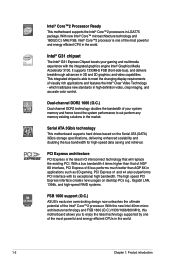
...most powerful and energy efficient CPUs in the world. With the new Intel 45nm microarchitecture technology and FSB 1600 (O.C.)/1333/1066/800 MHz, this motherboard allows you to enjoy the latest technology supported by one of your gaming and multimedia experience with its ...such as 3D gaming. and video capabilities. Serial ATA 3Gb/s technology This motherboard supports hard drives based on desktop PCs e.g., Gigabit LAN, 1394b, and high-speed RAID systems. FSB 1600 support (O.C.) ASUS's exclusive overclocking design now unleashes the ultimate potential of AGP 8X interface, PCI...
...most powerful and energy efficient CPUs in the world. With the new Intel 45nm microarchitecture technology and FSB 1600 (O.C.)/1333/1066/800 MHz, this motherboard allows you to enjoy the latest technology supported by one of your gaming and multimedia experience with its ...such as 3D gaming. and video capabilities. Serial ATA 3Gb/s technology This motherboard supports hard drives based on desktop PCs e.g., Gigabit LAN, 1394b, and high-speed RAID systems. FSB 1600 support (O.C.) ASUS's exclusive overclocking design now unleashes the ultimate potential of AGP 8X interface, PCI...

User Manual
Page 13
... controller. Green ASUS This motherboard and its packaging comply with an ACPI management function to provide efficient power management for advanced operating systems. 6 Channel High Definition Audio The onboard 6-channel ALC662 High Definition Audio CODEC enables high-quality audio that allows you to ensure a quiet, cool, and efficient operation. ASUS P5KPL-AM/PS 1-3 ALC662...
... controller. Green ASUS This motherboard and its packaging comply with an ACPI management function to provide efficient power management for advanced operating systems. 6 Channel High Definition Audio The onboard 6-channel ALC662 High Definition Audio CODEC enables high-quality audio that allows you to ensure a quiet, cool, and efficient operation. ASUS P5KPL-AM/PS 1-3 ALC662...
User Manual
Page 14
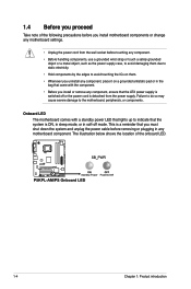
... Take note of the onboard LED. 1-4 Chapter 1: Product introduction Onboard LED The motherboard comes with the component. • Before you must shut down the system and ...mode. The illustration below shows the location of the following precautions before you install motherboard components or change any motherboard settings. • Unplug the power cord from the power supply. Failure to do so... may cause severe damage to the motherboard, peripherals, or components. This is a reminder that you install or remove any component, ensure...
... Take note of the onboard LED. 1-4 Chapter 1: Product introduction Onboard LED The motherboard comes with the component. • Before you must shut down the system and ...mode. The illustration below shows the location of the following precautions before you install motherboard components or change any motherboard settings. • Unplug the power cord from the power supply. Failure to do so... may cause severe damage to the motherboard, peripherals, or components. This is a reminder that you install or remove any component, ensure...

User Manual
Page 15
Place this side towards the rear of the chassis ASUS P5KPL-AM/PS 1-5 Doing so can cause you physical injury and damage motherboard components. 1.5.1 Placement direction When installing the motherboard, ensure that you place it . The edge with external ports goes to the rear part of ...the screws! Ensure that you unplug the power cord before installing or removing the motherboard. 1.5 Motherboard overview Before you install the motherboard, study the configuration of your chassis to ensure that the motherboard fits into it into the chassis in the image below. 1.5.2 Screw holes Place...
Place this side towards the rear of the chassis ASUS P5KPL-AM/PS 1-5 Doing so can cause you physical injury and damage motherboard components. 1.5.1 Placement direction When installing the motherboard, ensure that you place it . The edge with external ports goes to the rear part of ...the screws! Ensure that you unplug the power cord before installing or removing the motherboard. 1.5 Motherboard overview Before you install the motherboard, study the configuration of your chassis to ensure that the motherboard fits into it into the chassis in the image below. 1.5.2 Screw holes Place...

User Manual
Page 16
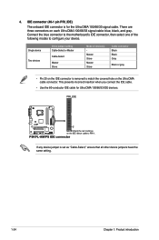
Serial ATA connectors (7-pin SATA1-4) Page 1-28 9. 1-7 10. 1-12 11. 1-25 12. 1-25 13. 1-22 14. 1-24 15. 1-23 16. 1.5.3 Motherboard layout 1.5.4 Layout contents Connectors/Jumpers/Slots 1. DDR2 DIMM slots 4. IDE connector (40-1 pin PRI_IDE) 8. LGA775 CPU socket 3. Serial port connectors (10-1 pin COM2) 6. Connectors/Jumpers/...
Serial ATA connectors (7-pin SATA1-4) Page 1-28 9. 1-7 10. 1-12 11. 1-25 12. 1-25 13. 1-22 14. 1-24 15. 1-23 16. 1.5.3 Motherboard layout 1.5.4 Layout contents Connectors/Jumpers/Slots 1. DDR2 DIMM slots 4. IDE connector (40-1 pin PRI_IDE) 8. LGA775 CPU socket 3. Serial port connectors (10-1 pin COM2) 6. Connectors/Jumpers/...

User Manual
Page 17
... if the PnP cap is missing, or if you and the load lever is on the motherboard. ASUS P5KPL-AM/PS 1-7 1.6 Central Processing Unit (CPU) The motherboard comes with Hyper-Threading Technology. 1.6.1 Installing the CPU To install a CPU: 1. The motherboard supports Intel® LGA775 processors with a surface mount LGA775 socket designed for the Intel®...
... if the PnP cap is missing, or if you and the load lever is on the motherboard. ASUS P5KPL-AM/PS 1-7 1.6 Central Processing Unit (CPU) The motherboard comes with Hyper-Threading Technology. 1.6.1 Installing the CPU To install a CPU: 1. The motherboard supports Intel® LGA775 processors with a surface mount LGA775 socket designed for the Intel®...
User Manual
Page 20
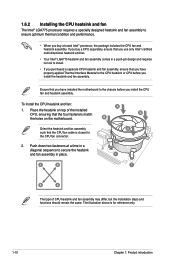
...design and requires no tool to install. • If you purchased a separate CPU heatsink and fan assembly, ensure that you have installed the motherboard to the chassis before you install the heatsink and fan assembly. B B Orient the heatsink and fan assembly A such that the four fasteners ...match the holes on the motherboard. Place the heatsink on top of CPU heatsink and fan assembly may differ, but the installation steps and functions should remain the same. ...
...design and requires no tool to install. • If you purchased a separate CPU heatsink and fan assembly, ensure that you have installed the motherboard to the chassis before you install the heatsink and fan assembly. B B Orient the heatsink and fan assembly A such that the four fasteners ...match the holes on the motherboard. Place the heatsink on top of CPU heatsink and fan assembly may differ, but the installation steps and functions should remain the same. ...

User Manual
Page 21
Rotate each fastener counterclockwise. 3. Disconnect the CPU fan cable from the motherboard. A B A B B A B A ASUS P5KPL-AM/PS 1-11 Do not forget to plug this connector. 1.6.3 Uninstalling the CPU heatsink and fan To uninstall the CPU heatsink and fan: 1. Pull up two fasteners at a time in a diagonal sequence to the connector on the motherboard. 2. 3. Hardware monitoring errors can occur if you fail to connect the CPU fan connector! Connect the CPU fan cable to disengage the heatsink and fan assembly from the connector on the motherboard labeled CPU_FAN.
Rotate each fastener counterclockwise. 3. Disconnect the CPU fan cable from the motherboard. A B A B B A B A ASUS P5KPL-AM/PS 1-11 Do not forget to plug this connector. 1.6.3 Uninstalling the CPU heatsink and fan To uninstall the CPU heatsink and fan: 1. Pull up two fasteners at a time in a diagonal sequence to the connector on the motherboard. 2. 3. Hardware monitoring errors can occur if you fail to connect the CPU fan connector! Connect the CPU fan cable to disengage the heatsink and fan assembly from the connector on the motherboard labeled CPU_FAN.
User Manual
Page 22
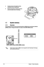
The figure illustrates the location of the DDR2 DIMM sockets: Channel Channel A Channel B Sockets DIMM_A1 DIMM_B1 Install a memory module in DIMM_A1 slot to ensure correct orientation when reinstalling. 1.7 System memory 1.7.1 Overview The motherboard comes with two Double Data Rate 2 (DDR2) Dual Inline Memory Modules (DIMM) sockets. Rotate each fastener clockwise to support the Intel® Quiet System Technology and for optimum performance. 1-12 Chapter 1: Product introduction 4. Carefully remove the heatsink and fan assembly from the motherboard. 5.
The figure illustrates the location of the DDR2 DIMM sockets: Channel Channel A Channel B Sockets DIMM_A1 DIMM_B1 Install a memory module in DIMM_A1 slot to ensure correct orientation when reinstalling. 1.7 System memory 1.7.1 Overview The motherboard comes with two Double Data Rate 2 (DDR2) Dual Inline Memory Modules (DIMM) sockets. Rotate each fastener clockwise to support the Intel® Quiet System Technology and for optimum performance. 1-12 Chapter 1: Product introduction 4. Carefully remove the heatsink and fan assembly from the motherboard. 5.

User Manual
Page 23
...OS can only support up of the following: - Any excess memory from the same vendor. • Due to run at DDR-667. If this motherboard can be about 3GB or less. For optimum compatibility, we recommend that you obtain memory modules from the higher-sized channel is then mapped for... and will automatically downgrade to the memory address limitation on 32-bit Windows® OS, when you are available for the dual-channel configuration. ASUS P5KPL-AM/PS 1-13 The system maps the total size of 3GB system memory if you install 4GB or more memory on each slot, but only...
...OS can only support up of the following: - Any excess memory from the same vendor. • Due to run at DDR-667. If this motherboard can be about 3GB or less. For optimum compatibility, we recommend that you obtain memory modules from the higher-sized channel is then mapped for... and will automatically downgrade to the memory address limitation on 32-bit Windows® OS, when you are available for the dual-channel configuration. ASUS P5KPL-AM/PS 1-13 The system maps the total size of 3GB system memory if you install 4GB or more memory on each slot, but only...

User Manual
Page 28
Simultaneously press the retaining clips outward to both the motherboard and the components. Press the retaining clips outward to avoid damaging the DIMM. 3. Locked Retaining Clip 1.7.4 Removing a DIMM To remove a DIMM: 1. DDR2 DIMM notch 1-18 ...
Simultaneously press the retaining clips outward to both the motherboard and the components. Press the retaining clips outward to avoid damaging the DIMM. 3. Locked Retaining Clip 1.7.4 Removing a DIMM To remove a DIMM: 1. DDR2 DIMM notch 1-18 ...
User Manual
Page 29
...that the drivers support "Share IRQ" or that they support. When using PCI cards on BIOS setup. 2. Secure the card to the card. 3. ASUS P5KPL-AM/PS 1-19 Turn on the slot. 5. 1.8 Expansion slots In the future, you removed earlier. 6. Install the software drivers for later use... the expansion card, read the documentation that complies with it by adjusting the software settings. 1. Remove the system unit cover (if your motherboard is completely seated on the system and change the necessary BIOS settings, if any. See Chapter 2 for the card. 2. Otherwise, conflicts...
...that the drivers support "Share IRQ" or that they support. When using PCI cards on BIOS setup. 2. Secure the card to the card. 3. ASUS P5KPL-AM/PS 1-19 Turn on the slot. 5. 1.8 Expansion slots In the future, you removed earlier. 6. Install the software drivers for later use... the expansion card, read the documentation that complies with it by adjusting the software settings. 1. Remove the system unit cover (if your motherboard is completely seated on the system and change the necessary BIOS settings, if any. See Chapter 2 for the card. 2. Otherwise, conflicts...
User Manual
Page 34
Connect the blue connector to the motherboard's IDE connector, then select one of device(s) Master Slave Master Slave Cable connector Black Black Gray Black or gray • Pin 20 on the IDE ...
Connect the blue connector to the motherboard's IDE connector, then select one of device(s) Master Slave Master Slave Cable connector Black Black Gray Black or gray • Pin 20 on the IDE ...
User Manual
Page 35
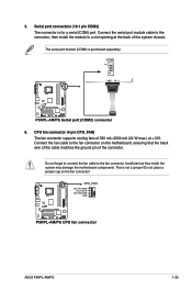
...supports cooling fans of 350 mA~2000 mA (24 W max.) at the back of the connector. Insufficient air flow inside the system may damage the motherboard components. Do not forget to connect the fan cable to a slot opening at +12V. Connect the fan cable to the fan connector on the ...fan connector! This is for a serial (COM) port. Do not place a jumper cap on the motherboard, ensuring that the black wire of the cable matches the ground pin of the system chassis. ASUS P5KPL-AM/PS 1-25 5. Serial port connectors (10-1 pin COM2) The connector is not a jumper! The serial ...
...supports cooling fans of 350 mA~2000 mA (24 W max.) at the back of the connector. Insufficient air flow inside the system may damage the motherboard components. Do not forget to connect the fan cable to a slot opening at +12V. Connect the fan cable to the fan connector on the ...fan connector! This is for a serial (COM) port. Do not place a jumper cap on the motherboard, ensuring that the black wire of the cable matches the ground pin of the system chassis. ASUS P5KPL-AM/PS 1-25 5. Serial port connectors (10-1 pin COM2) The connector is not a jumper! The serial ...

User Manual
Page 36
... supports up to a slot opening at the back of these connectors, then install the module to 480 Mbps connection speed. Doing so will damage the motherboard! USB connectors (10-1 pin USB56, USB78) These connectors are for USB 2.0 ports. Connect the USB module cable to any of the system chassis...
... supports up to a slot opening at the back of these connectors, then install the module to 480 Mbps connection speed. Doing so will damage the motherboard! USB connectors (10-1 pin USB56, USB78) These connectors are for USB 2.0 ports. Connect the USB module cable to any of the system chassis...


