
User Manual
Page 31
exe 2 DOS afudos /o[filename filename A:\>afudos /oOLDBIOS1.rom 3. 按下 afudos /oOLDBIOS1.rom AMI Firmware Update Utility - ok A:\> 當 BIOS DOS 31 Reading flash ..... BIOS 2.1 使用 AFUDOS BIOS AFUDOS DOS BIOS BIOS 程式。AFUDOS BIOS BIOS BIOS 程式 BIOS 程式。 1.2MB BIOS 1 AFUDOS 程式(afudos. Version 1.19(ASUS V2.07(03.11.24BB)) Copyright (C) 2002 American Megatrends, Inc. All rights reserved. done Write to file......
exe 2 DOS afudos /o[filename filename A:\>afudos /oOLDBIOS1.rom 3. 按下 afudos /oOLDBIOS1.rom AMI Firmware Update Utility - ok A:\> 當 BIOS DOS 31 Reading flash ..... BIOS 2.1 使用 AFUDOS BIOS AFUDOS DOS BIOS BIOS 程式。AFUDOS BIOS BIOS BIOS 程式 BIOS 程式。 1.2MB BIOS 1 AFUDOS 程式(afudos. Version 1.19(ASUS V2.07(03.11.24BB)) Copyright (C) 2002 American Megatrends, Inc. All rights reserved. done Write to file......

User Manual
Page 32
... - Do not turn off power during flash BIOS Reading file ....... done Writing flash ...... WARNING!! done Advance Check ...... Erasing flash ...... All rights reserved. done Advance Check ...... 更新 BIOS 程式 AFUDOS BIOS 程式。 1 tw.asus.com BIOS 片中。 BIOS BIOS 2. 將 AFUDOS.EXE BIOS 3 DOS afudos /i[filename filename BIOS 程式。 A:\>afudos /iP5B-VM...
... - Do not turn off power during flash BIOS Reading file ....... done Writing flash ...... WARNING!! done Advance Check ...... Erasing flash ...... All rights reserved. done Advance Check ...... 更新 BIOS 程式 AFUDOS BIOS 程式。 1 tw.asus.com BIOS 片中。 BIOS BIOS 2. 將 AFUDOS.EXE BIOS 3 DOS afudos /i[filename filename BIOS 程式。 A:\>afudos /iP5B-VM...

User Manual
Page 33
.../13/2006 Flash Type - 2.2 使用 AwardBIOS Flash BIOS AwardBIOS Flash AwardBIOS Flash 程式(AWDFLASH.EXE BIOS AwardBIOS Flash BIOS 程式。 1 http://tw.asus.com BIOS M2N-VM HDMI.bin FAT 32/16 格式的 USB BIOS 2 CD/DVD AwardBIOS Flash BIOS 3 DOS 4. 當 A BIOS 檔案與 AwardBIOS Flash 5 A awdflash 並按...
.../13/2006 Flash Type - 2.2 使用 AwardBIOS Flash BIOS AwardBIOS Flash AwardBIOS Flash 程式(AWDFLASH.EXE BIOS AwardBIOS Flash BIOS 程式。 1 http://tw.asus.com BIOS M2N-VM HDMI.bin FAT 32/16 格式的 USB BIOS 2 CD/DVD AwardBIOS Flash BIOS 3 DOS 4. 當 A BIOS 檔案與 AwardBIOS Flash 5 A awdflash 並按...

User Manual
Page 34
...Power Or Reset System! 在更新 BIOS 9 Flash Complete BIOS F1 AwardBIOS Flash Utility for ASUS V1.14 (C) Phoenix Technologies Ltd. PMC Pm49FL004T LPC/FWH File Name to Continue Write OK F1 Reset No Update Write Fail 34 BIOS All Rights Reserved For C51PV-MCP51-M2A-VM ...HDMI-00 DATE:04/13/2006 Flash Type - 7 BIOS N BIOS 8 BIOS BIOS AwardBIOS Flash Utility for ASUS V1.14 (C) Phoenix Technologies Ltd. All Rights Reserved For C51PV-MCP51...
...Power Or Reset System! 在更新 BIOS 9 Flash Complete BIOS F1 AwardBIOS Flash Utility for ASUS V1.14 (C) Phoenix Technologies Ltd. PMC Pm49FL004T LPC/FWH File Name to Continue Write OK F1 Reset No Update Write Fail 34 BIOS All Rights Reserved For C51PV-MCP51-M2A-VM ...HDMI-00 DATE:04/13/2006 Flash Type - 7 BIOS N BIOS 8 BIOS BIOS AwardBIOS Flash Utility for ASUS V1.14 (C) Phoenix Technologies Ltd. All Rights Reserved For C51PV-MCP51...
User Manual
Page 3
... 1-2 1.2.1 Motherboard layout 1-2 1.2.2 Layout contents 1-2 1.3 Central Processing Unit (CPU 1-3 1.4 System memory 1-3 1.4.1 Overview 1-3 1.4.2 Memory configurations 1-3 1.5 Expansion slots 1-7 1.5.1 PCI slot 1-7 1.5.2 PCI Express x1 slot 1-7 1.5.3 PCI Express x16 slot 1-7 1.6 Jumpers 1-7 1.7 Connectors 1-9 1.7.1 Rear panel ports 1-9 1.7.2 Internal connectors 1-10 1.8 Software support 1-15 1.8.1 Installing an operating system 1-15 1.8.2 Support DVD information 1-15 Chapter 2: BIOS information 2.1 Managing and updating your BIOS 2-1 2.1.1 ASUS...
... 1-2 1.2.1 Motherboard layout 1-2 1.2.2 Layout contents 1-2 1.3 Central Processing Unit (CPU 1-3 1.4 System memory 1-3 1.4.1 Overview 1-3 1.4.2 Memory configurations 1-3 1.5 Expansion slots 1-7 1.5.1 PCI slot 1-7 1.5.2 PCI Express x1 slot 1-7 1.5.3 PCI Express x16 slot 1-7 1.6 Jumpers 1-7 1.7 Connectors 1-9 1.7.1 Rear panel ports 1-9 1.7.2 Internal connectors 1-10 1.8 Software support 1-15 1.8.1 Installing an operating system 1-15 1.8.2 Support DVD information 1-15 Chapter 2: BIOS information 2.1 Managing and updating your BIOS 2-1 2.1.1 ASUS...
User Manual
Page 6
... power cables from the existing system before you need when installing and configuring the motherboard. Detailed descriptions of the electrical outlet you are not sure about the voltage of the BIOS parameters are not damaged. If possible, disconnect all power cables are unplugged. &#...• Avoid dust, humidity, and temperature extremes. About this guide is set to change system settings through the BIOS setup menus. Operation safety • Before installing the motherboard and adding devices on a flat and stable surface. • If you detect any damage, contact your area....
... power cables from the existing system before you need when installing and configuring the motherboard. Detailed descriptions of the electrical outlet you are not sure about the voltage of the BIOS parameters are not damaged. If possible, disconnect all power cables are unplugged. &#...• Avoid dust, humidity, and temperature extremes. About this guide is set to change system settings through the BIOS setup menus. Operation safety • Before installing the motherboard and adding devices on a flat and stable surface. • If you detect any damage, contact your area....
User Manual
Page 8
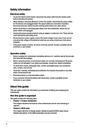
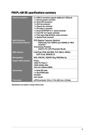
Maximum resolution: 2048 x 1536 x 32 bpp, - Maximum shared memory of 256 MB - P5KPL-AM SE specifications summary CPU Chipset Front Side Bus Memory Expansion Slots VGA Storage LAN Audio USB ASUS Features Rear panel LGA775 socket for Intel® Core™2 Quad/ Core™2 Extreme / Core™...high-Definition Audio CODEC Anti-Pop function Jack-detect & Multi-Streaming Max. 8 x USB2.0 ports (4 ports at mid-board, 4 ports at back panel ASUS CrashFree BIOS 3 ASUS Q-Fan ASUS EZ Flash 2 ASUS MyLogo 2 1 x PS/2 keyboard port 1 x PS/2 mouse port 1 x VGA port 1 x COM 1 x LAN (RJ-45) port 4 ...
Maximum resolution: 2048 x 1536 x 32 bpp, - Maximum shared memory of 256 MB - P5KPL-AM SE specifications summary CPU Chipset Front Side Bus Memory Expansion Slots VGA Storage LAN Audio USB ASUS Features Rear panel LGA775 socket for Intel® Core™2 Quad/ Core™2 Extreme / Core™...high-Definition Audio CODEC Anti-Pop function Jack-detect & Multi-Streaming Max. 8 x USB2.0 ports (4 ports at mid-board, 4 ports at back panel ASUS CrashFree BIOS 3 ASUS Q-Fan ASUS EZ Flash 2 ASUS MyLogo 2 1 x PS/2 keyboard port 1 x PS/2 mouse port 1 x VGA port 1 x COM 1 x LAN (RJ-45) port 4 ...
User Manual
Page 9
... connector 1 x 24-pin EATXPWR 12 V power connector 1 x 4-pin ATX 12 V power connector 1 x Front panel High Definition audio connector 1 x System Panel connector SFS (Stepless Frequency Selection) - FSB turning from 133MHz up to change without notice. ix P5KPL-AM SE specifications summary Internal connectors ASUS Exclusive Overclocking Features BIOS features Manageability Support DVD contents Accessories Form factor...
... connector 1 x 24-pin EATXPWR 12 V power connector 1 x 4-pin ATX 12 V power connector 1 x Front panel High Definition audio connector 1 x System Panel connector SFS (Stepless Frequency Selection) - FSB turning from 133MHz up to change without notice. ix P5KPL-AM SE specifications summary Internal connectors ASUS Exclusive Overclocking Features BIOS features Manageability Support DVD contents Accessories Form factor...
User Manual
Page 11
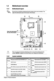
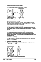
...) 6. Internal speaker connector (4-pin SPEAKER) Page Connectors/Jumpers/Slots 1-13 9. ATX power connectors (24-pin EATXPWR, 4-pin ATX12V) 2. DDR2 DIMM slots 4. ...I/O Lithium Cell CMOS Power PCIEX1_1 P5KPL-AM SE SPEAKER Intel® ICH7 ALC662 AAFP F_PANEL CD PCI1 SB_PWR USBPW5-8 USB78 CLRTC USB56 PRI_IDE 8Mb BIOS SATA2 SATA1 Place six screws into... (10-1 pin AAFP) 1-11 14. 1.2 1.2.1 Motherboard overview Motherboard layout Ensure that you install the motherboard into the holes indicated by circles to secure the motherboard to the rear part of the chassis. 24.4cm...
...) 6. Internal speaker connector (4-pin SPEAKER) Page Connectors/Jumpers/Slots 1-13 9. ATX power connectors (24-pin EATXPWR, 4-pin ATX12V) 2. DDR2 DIMM slots 4. ...I/O Lithium Cell CMOS Power PCIEX1_1 P5KPL-AM SE SPEAKER Intel® ICH7 ALC662 AAFP F_PANEL CD PCI1 SB_PWR USBPW5-8 USB78 CLRTC USB56 PRI_IDE 8Mb BIOS SATA2 SATA1 Place six screws into... (10-1 pin AAFP) 1-11 14. 1.2 1.2.1 Motherboard overview Motherboard layout Ensure that you install the motherboard into the holes indicated by circles to secure the motherboard to the rear part of the chassis. 24.4cm...

User Manual
Page 17
.... • You do not help, remove the onboard battery and move the cap back to re- CLRTC 12 23 P5KPL-AM SE Normal (Default) Clear RTC P5KPL-AM SE Clear RTC RAM Chapter 1: Product introduction 1-8 enter data. Shut down the key during the boot process and enter... BIOS setup to pins 1-2. 4. Hold down and reboot the system, then the BIOS automatically resets the parameter settings to default values. • Due to ...
.... • You do not help, remove the onboard battery and move the cap back to re- CLRTC 12 23 P5KPL-AM SE Normal (Default) Clear RTC P5KPL-AM SE Clear RTC RAM Chapter 1: Product introduction 1-8 enter data. Shut down the key during the boot process and enter... BIOS setup to pins 1-2. 4. Hold down and reboot the system, then the BIOS automatically resets the parameter settings to default values. • Due to ...
User Manual
Page 18
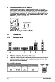
...(the default is for the rear USB ports. The USBPW56 jumper is for a PS/2 mouse. 2. PS/2 mouse port (green). 3. This feature requires an ATX power supply that can wake up feature. This port is the Space Bar), clicking the mouse, or using a USB device. When you set this jumper...in the BIOS. Refer to a Local Area Network (LAN) through a network hub. LAN port LED indications Status OFF Blink Blink ACT LED Description No link Data activity Data activity Status OFF OFF Orange Speed LED Description No link 10M 100M ACT/LINK SPEED LED LED LAN port 1-9 ASUS P5KPL-AM SE LAN (...
...(the default is for the rear USB ports. The USBPW56 jumper is for a PS/2 mouse. 2. PS/2 mouse port (green). 3. This feature requires an ATX power supply that can wake up feature. This port is the Space Bar), clicking the mouse, or using a USB device. When you set this jumper...in the BIOS. Refer to a Local Area Network (LAN) through a network hub. LAN port LED indications Status OFF Blink Blink ACT LED Description No link Data activity Data activity Status OFF OFF Orange Speed LED Description No link 10M 100M ACT/LINK SPEED LED LED LAN port 1-9 ASUS P5KPL-AM SE LAN (...
User Manual
Page 21
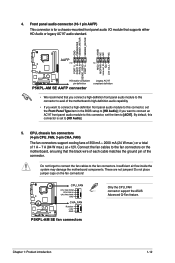
..., set the Front Panel Type item in the BIOS setup to [HD Audio]. 5. These are not jumpers! Do not place jumper caps on the motherboard, ensuring that the black wire of each cable matches the ground pin of the connector. 4. P5KPL-AM SE CPU_FAN CPU FAN PWM CPU FAN IN CPU FAN... PWR GND CHA_FAN Rotation +12V GND P5KPL-AM SE fan connectors Only the CPU_FAN connector support the ASUS Advanced Q-Fan feature. ...
..., set the Front Panel Type item in the BIOS setup to [HD Audio]. 5. These are not jumpers! Do not place jumper caps on the motherboard, ensuring that the black wire of each cable matches the ground pin of the connector. 4. P5KPL-AM SE CPU_FAN CPU FAN PWM CPU FAN IN CPU FAN... PWR GND CHA_FAN Rotation +12V GND P5KPL-AM SE fan connectors Only the CPU_FAN connector support the ASUS Advanced Q-Fan feature. ...
User Manual
Page 23
... CD) These connectors allow you turn on the BIOS settings. CD Right Audio Channel GND GND Left Audio Channel P5KPL-AM SE P5KPL-AM SE Internal audio connector Chapter 1: Product introduction 1-14 PWR LED PWR BTN F_PANEL PIN 1 P5KPL-AM SE HD_LED RESET P5KPL-AM SE System panel connector • System power LED ...(2-pin PWRLED) This 2-pin connector is for the chassis-mounted reset button for the HDD Activity LED. Connect the chassis power LED cable to the HDD. • ATX power button/soft-...
... CD) These connectors allow you turn on the BIOS settings. CD Right Audio Channel GND GND Left Audio Channel P5KPL-AM SE P5KPL-AM SE Internal audio connector Chapter 1: Product introduction 1-14 PWR LED PWR BTN F_PANEL PIN 1 P5KPL-AM SE HD_LED RESET P5KPL-AM SE System panel connector • System power LED ...(2-pin PWRLED) This 2-pin connector is for the chassis-mounted reset button for the HDD Activity LED. Connect the chassis power LED cable to the HDD. • ATX power button/soft-...
User Manual
Page 25
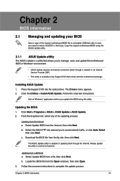
... Next. Quit all its features. b. c. Select Update BIOS from the Open windows, then click Open. 3. Follow the onscreen instructions. Updating the BIOS: 1. Select Update BIOS from the ftp site, then click Next. b. Installing ASUS Update: 1. Chapter 2 BIOS information 2.1 Managing and updating your BIOS Save a copy of the original motherboard BIOS file to a bootable USB flash disk in case...
... Next. Quit all its features. b. c. Select Update BIOS from the Open windows, then click Open. 3. Follow the onscreen instructions. Updating the BIOS: 1. Select Update BIOS from the ftp site, then click Next. b. Installing ASUS Update: 1. Chapter 2 BIOS information 2.1 Managing and updating your BIOS Save a copy of the original motherboard BIOS file to a bootable USB flash disk in case...
User Manual
Page 26
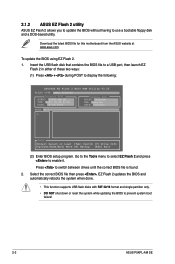
... Tools menu to select EZ Flash 2 and press to prevent system boot failure! 2-2 ASUS P5KPL-AM SE Select the correct BIOS file then press , EZ Flash 2 updates the BIOS and automatically reboots the system when done. • This function supports USB flash disks ...motherboard from the ASUS website at www.asus.com. Insert the USB flash disk that contains the BIOS file to a USB port, then launch EZ Flash 2 in either of these two ways: (1) Press + during POST to display the following: ASUSTek EZ Flash 2 BIOS ROM Utility V3.25 FLASH TYPE: MXIC 25L8005 Current ROM BOARD: P5KPL-AM SE...
... Tools menu to select EZ Flash 2 and press to prevent system boot failure! 2-2 ASUS P5KPL-AM SE Select the correct BIOS file then press , EZ Flash 2 updates the BIOS and automatically reboots the system when done. • This function supports USB flash disks ...motherboard from the ASUS website at www.asus.com. Insert the USB flash disk that contains the BIOS file to a USB port, then launch EZ Flash 2 in either of these two ways: (1) Press + during POST to display the following: ASUSTek EZ Flash 2 BIOS ROM Utility V3.25 FLASH TYPE: MXIC 25L8005 Current ROM BOARD: P5KPL-AM SE...
User Manual
Page 27
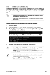
... or a USB flash disk with FAT 32/16 format and single partition supports ASUS CrashFree BIOS 3. Checking for CD-ROM... Bad BIOS checksum. Doing so can update a corrupted BIOS file using the motherboard Support DVD or a USB flash disk that allows you to your computer. 3. Chapter 2: BIOS information 2-3 otherwise, the utility will not function. Recovering the...
... or a USB flash disk with FAT 32/16 format and single partition supports ASUS CrashFree BIOS 3. Checking for CD-ROM... Bad BIOS checksum. Doing so can update a corrupted BIOS file using the motherboard Support DVD or a USB flash disk that allows you to your computer. 3. Chapter 2: BIOS information 2-3 otherwise, the utility will not function. Recovering the...
User Manual
Page 28
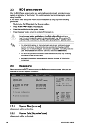
... properly from a running operating system can cause damage to ensure optimum performance. See section 2.8 Exit menu. • The BIOS setup screens in this motherboard apply to most conditions to your system, or prompted to turn the system off then back on...2-4 ASUS P5KPL-AM SE We recommend that you want to configure system time. Storage Configuration System Information Select Screen Select Item +- Use [+] or [-] to enter Setup after changing any of the basic system information. If the system becomes unstable after POST, reboot the system by doing any BIOS settings...
... properly from a running operating system can cause damage to ensure optimum performance. See section 2.8 Exit menu. • The BIOS setup screens in this motherboard apply to most conditions to your system, or prompted to turn the system off then back on...2-4 ASUS P5KPL-AM SE We recommend that you want to configure system time. Storage Configuration System Information Select Screen Select Item +- Use [+] or [-] to enter Setup after changing any of the basic system information. If the system becomes unstable after POST, reboot the system by doing any BIOS settings...
User Manual
Page 29
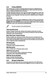
...[Auto] Enables or disables data multi-sectors transfers. Configuration options: [Auto] [0] [1] [2] [3] [4] DMA Mode [Auto] Selects the DMA mode. The BIOS automatically detects the values opposite the dimmed items (Device, Vendor, Size, LBA Mode, Block Mode, PIO Mode, Async DMA, Ultra DMA, and SMART monitoring... [Enabled] 2.3.4 Storage Configuration The items in this mode, and if the device was not previously formatted with LBA mode disabled. Chapter 2: BIOS information 2-5 Configuration options: [Disabled] [Auto] PIO Mode [Auto] Selects the PIO mode. Select [CDROM] if you to set to...
...[Auto] Enables or disables data multi-sectors transfers. Configuration options: [Auto] [0] [1] [2] [3] [4] DMA Mode [Auto] Selects the DMA mode. The BIOS automatically detects the values opposite the dimmed items (Device, Vendor, Size, LBA Mode, Block Mode, PIO Mode, Async DMA, Ultra DMA, and SMART monitoring... [Enabled] 2.3.4 Storage Configuration The items in this mode, and if the device was not previously formatted with LBA mode disabled. Chapter 2: BIOS information 2-5 Configuration options: [Disabled] [Auto] PIO Mode [Auto] Selects the PIO mode. Select [CDROM] if you to set to...
User Manual
Page 30
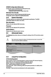
... the auto-detected BIOS information. allows you to achieve desired CPU internal frequency. loads overclocking profiles with spread spectrum. 2-6 ASUS P5KPL-AM SE Processor Displays the auto-detected CPU specification. JumperFree Configuration USB Configuration CPU Configuration Chipset Onboard .... loads the optimal settings for detecting ATA/ATAPI devices. Select either one of the general system specifications. Auto - The BIOS automatically detects the items in this menu. Take caution when changing the settings of CPU overclocking options to individually set overclocking ...
... the auto-detected BIOS information. allows you to achieve desired CPU internal frequency. loads overclocking profiles with spread spectrum. 2-6 ASUS P5KPL-AM SE Processor Displays the auto-detected CPU specification. JumperFree Configuration USB Configuration CPU Configuration Chipset Onboard .... loads the optimal settings for detecting ATA/ATAPI devices. Select either one of the general system specifications. Auto - The BIOS automatically detects the items in this menu. Take caution when changing the settings of CPU overclocking options to individually set overclocking ...
User Manual
Page 31
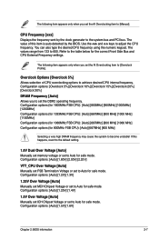
...4V] 1.5V Over Voltage [Auto] Manually set ICH Chipset Voltage or set to Auto for safe mode. Configuration options: [Auto] [1.5V] [1.6V] Chapter 2: BIOS information 2-7 Refer to become unstable! Configuration options: [Auto] [1.80V] [2.00V] [2.25V] VTT_CPU Over Voltage [Auto] Manually set FSB Termination Voltage or set to...Auto] Manually set MCH Chipset Voltage or set to Auto for safe mode. CPU Frequency [xxx] Displays the frequency sent by the BIOS. You can also type the desired CPU frequency using the numeric keypad. The following item appears only when you set the DDR2 ...
...4V] 1.5V Over Voltage [Auto] Manually set ICH Chipset Voltage or set to Auto for safe mode. Configuration options: [Auto] [1.5V] [1.6V] Chapter 2: BIOS information 2-7 Refer to become unstable! Configuration options: [Auto] [1.80V] [2.00V] [2.25V] VTT_CPU Over Voltage [Auto] Manually set FSB Termination Voltage or set to...Auto] Manually set MCH Chipset Voltage or set to Auto for safe mode. CPU Frequency [xxx] Displays the frequency sent by the BIOS. You can also type the desired CPU frequency using the numeric keypad. The following item appears only when you set the DDR2 ...


