

Motherboard Installation Guide
Page 20
...:Rear Speaker Out Center: Side Speaker Out Below: Center/Subwoofer Intel® 915GV MCH EATXPWR PRI_IDE PCIEX16(x4 mode) RTL8100C PCI1 AD1986A AAFP CD PCI2 P5GV-MX PCI3 SB_PWR SPDIF_OUT CR2032 3V Lithium Cell CMOS Power Intel ICH6 SATA4 SATA3 SATA2 SATA1 CLRTC USBPW78 USB56 USBPW56 USB78 4Mb...
...:Rear Speaker Out Center: Side Speaker Out Below: Center/Subwoofer Intel® 915GV MCH EATXPWR PRI_IDE PCIEX16(x4 mode) RTL8100C PCI1 AD1986A AAFP CD PCI2 P5GV-MX PCI3 SB_PWR SPDIF_OUT CR2032 3V Lithium Cell CMOS Power Intel ICH6 SATA4 SATA3 SATA2 SATA1 CLRTC USBPW78 USB56 USBPW56 USB78 4Mb...
Motherboard DIY Troubleshooting Guide
Page 4
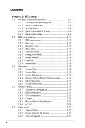
... 2.1 Managing and updating your BIOS 2-2 2.1.1 Creating a bootable floppy disk 2-2 2.1.2 ASUS EZ Flash utility 2-3 2.1.3 AFUDOS utility 2-4 2.1.4 ASUS CrashFree BIOS 2 utility 2-6 2.1.5 ASUS Update utility 2-8 2.2 BIOS setup program 2-11 2.2.1 BIOS menu screen 2-12 2.2.2 Menu bar 2-12 2.2.3 Navigation keys 2-12 2.2.4 Menu items 2-13 2.2.5 Sub-menu items 2-13 2.2.6 Configuration fields 2-13 2.2.7 Pop-up window 2-...
... 2.1 Managing and updating your BIOS 2-2 2.1.1 Creating a bootable floppy disk 2-2 2.1.2 ASUS EZ Flash utility 2-3 2.1.3 AFUDOS utility 2-4 2.1.4 ASUS CrashFree BIOS 2 utility 2-6 2.1.5 ASUS Update utility 2-8 2.2 BIOS setup program 2-11 2.2.1 BIOS menu screen 2-12 2.2.2 Menu bar 2-12 2.2.3 Navigation keys 2-12 2.2.4 Menu items 2-13 2.2.5 Sub-menu items 2-13 2.2.6 Configuration fields 2-13 2.2.7 Pop-up window 2-...

Motherboard DIY Troubleshooting Guide
Page 8
...configuring the motherboard. Where to find more information Refer to perform when installing system components. Detailed descriptions of the BIOS parameters are not part of the motherboard and the new technologies it supports. These documents are also provided. • ...the motherboard supports. Refer to change system settings through the BIOS Setup menus. viii ASUS websites The ASUS website provides updated information on the motherboard. • Chapter 2: BIOS setup This chapter tells how to the ASUS contact information. 2. About this guide is organized This ...
...configuring the motherboard. Where to find more information Refer to perform when installing system components. Detailed descriptions of the BIOS parameters are not part of the motherboard and the new technologies it supports. These documents are also provided. • ...the motherboard supports. Refer to change system settings through the BIOS Setup menus. viii ASUS websites The ASUS website provides updated information on the motherboard. • Chapter 2: BIOS setup This chapter tells how to the ASUS contact information. 2. About this guide is organized This ...

Motherboard DIY Troubleshooting Guide
Page 10
...sockets support up to use only qualified graphics cards. P5GV-MX specifications summary CPU Chipset Front Side Bus Memory Expansion slots VGA Storage Audio LAN USB Special features BIOS features Rear Panel LGA775 socket for qualified PCI Express graphics...1 x PCI Express x16 slot (max 2GB/s, x4 mode) 3 x PCI slots (Note: Make sure to 8 USB 2.0 ports ASUS CPU Lock Free ASUS Q-FAN ASUS MyLogo ASUS EZ Flash ASUS CrashFree BIOS 2 4 MB Flash ROM, AMI BIOS, PnP, DMI2.0, WfM2.0, SM BIOS 2.3, PXE, RPL 1 x Parallel port 1 x LAN (RJ-45) port 4 x USB 2.0 ports 1 x Serial port (COM...
...sockets support up to use only qualified graphics cards. P5GV-MX specifications summary CPU Chipset Front Side Bus Memory Expansion slots VGA Storage Audio LAN USB Special features BIOS features Rear Panel LGA775 socket for qualified PCI Express graphics...1 x PCI Express x16 slot (max 2GB/s, x4 mode) 3 x PCI slots (Note: Make sure to 8 USB 2.0 ports ASUS CPU Lock Free ASUS Q-FAN ASUS MyLogo ASUS EZ Flash ASUS CrashFree BIOS 2 4 MB Flash ROM, AMI BIOS, PnP, DMI2.0, WfM2.0, SM BIOS 2.3, PXE, RPL 1 x Parallel port 1 x LAN (RJ-45) port 4 x USB 2.0 ports 1 x Serial port (COM...

Motherboard DIY Troubleshooting Guide
Page 15
... in the 775-land package. The Intel® ICH6 Southbridge represents the sixth generation I /O controller hub provide the vital interfaces for details. Making the appropriate BIOS setting automatically reduces the CPU multiplier value for enhanced 3D, 2D, and video performances. See the Appendix for PCI Express and Serial ATA. The GMCH... Memory 64 Technology (EM64T). The motherboard also supports the Intel® Hyper-Threading Technology and is fully compatible with Intel® 04B and 04A processors. ASUS P5GV-MX 1-3
... in the 775-land package. The Intel® ICH6 Southbridge represents the sixth generation I /O controller hub provide the vital interfaces for details. Making the appropriate BIOS setting automatically reduces the CPU multiplier value for enhanced 3D, 2D, and video performances. See the Appendix for PCI Express and Serial ATA. The GMCH... Memory 64 Technology (EM64T). The motherboard also supports the Intel® Hyper-Threading Technology and is fully compatible with Intel® 04B and 04A processors. ASUS P5GV-MX 1-3

Motherboard DIY Troubleshooting Guide
Page 17
See pages 1-24, 1-27, 1-30 and 2-21 for critical components. 1.3.2 Innovative ASUS features CrashFree BIOS 2 This feature allows you to personalize and add style to prevent overheating and damage. This protection eliminates the need to ensure... is backward compatible with customizable boot logos. USB 2.0 is monitored for each parameter. ASUS MyLogo™ This new feature present in case the system hangs due to overclocking. Simply shut down and reboot the system, and the BIOS automatically restores the CPU default setting for timely failure detection. ASUS P5GV-MX 1-5
See pages 1-24, 1-27, 1-30 and 2-21 for critical components. 1.3.2 Innovative ASUS features CrashFree BIOS 2 This feature allows you to personalize and add style to prevent overheating and damage. This protection eliminates the need to ensure... is backward compatible with customizable boot logos. USB 2.0 is monitored for each parameter. ASUS MyLogo™ This new feature present in case the system hangs due to overclocking. Simply shut down and reboot the system, and the BIOS automatically restores the CPU default setting for timely failure detection. ASUS P5GV-MX 1-5

Motherboard DIY Troubleshooting Guide
Page 20
...:Rear Speaker Out Center: Side Speaker Out Below: Center/Subwoofer Intel® 915GV MCH EATXPWR PRI_IDE PCIEX16(x4 mode) RTL8100C PCI1 AD1986A AAFP CD PCI2 P5GV-MX PCI3 SB_PWR SPDIF_OUT CR2032 3V Lithium Cell CMOS Power Intel ICH6 SATA4 SATA3 SATA2 SATA1 CLRTC USB56 USBPW78 USBPW56 USB78 4Mb...
...:Rear Speaker Out Center: Side Speaker Out Below: Center/Subwoofer Intel® 915GV MCH EATXPWR PRI_IDE PCIEX16(x4 mode) RTL8100C PCI1 AD1986A AAFP CD PCI2 P5GV-MX PCI3 SB_PWR SPDIF_OUT CR2032 3V Lithium Cell CMOS Power Intel ICH6 SATA4 SATA3 SATA2 SATA1 CLRTC USB56 USBPW78 USBPW56 USB78 4Mb...
Motherboard DIY Troubleshooting Guide
Page 32
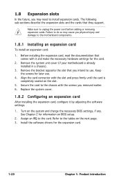
...before adding or removing expansion cards. Install the software drivers for information on the next page. 3. Assign an IRQ to the tables on BIOS setup. 2. The following sub-sections describe the expansion slots and the cards that you physical injury and damage to install expansion cards. ... you removed earlier. 6. Remove the system unit cover (if your motherboard is completely seated on the system and change the necessary BIOS settings, if any. Make sure to the chassis with the slot and press firmly until the card is already installed in a chassis). 3....
...before adding or removing expansion cards. Install the software drivers for information on the next page. 3. Assign an IRQ to the tables on BIOS setup. 2. The following sub-sections describe the expansion slots and the cards that you physical injury and damage to install expansion cards. ... you removed earlier. 6. Remove the system unit cover (if your motherboard is completely seated on the system and change the necessary BIOS settings, if any. Make sure to the chassis with the slot and press firmly until the card is already installed in a chassis). 3....

Motherboard DIY Troubleshooting Guide
Page 35
... the jumper cap from pins 1-2 (default) to overclocking. Re-install the battery. 5. ASUS P5GV-MX 1-23 The onboard button cell battery powers the RAM data in CMOS. Hold down and reboot the system so the BIOS can clear the CMOS memory of date, time, and system setup parameters by erasing the...RAM in CMOS, which include system setup information such as system passwords. 1.9 Jumpers 1. Removing the cap will cause system boot failure! ® P5GV-MX P5GV-MX Clear RTC RAM CLRTC 12 23 Normal (Default) Clear CMOS You do not need to clear the RTC when the system hangs due to pins...
... the jumper cap from pins 1-2 (default) to overclocking. Re-install the battery. 5. ASUS P5GV-MX 1-23 The onboard button cell battery powers the RAM data in CMOS. Hold down and reboot the system so the BIOS can clear the CMOS memory of date, time, and system setup parameters by erasing the...RAM in CMOS, which include system setup information such as system passwords. 1.9 Jumpers 1. Removing the cap will cause system boot failure! ® P5GV-MX P5GV-MX Clear RTC RAM CLRTC 12 23 Normal (Default) Clear CMOS You do not need to clear the RTC when the system hangs due to pins...

Motherboard DIY Troubleshooting Guide
Page 37
This feature requires an ATX power supply that can supply at least 1A on the keyboard (the default is the Space Bar). 3. Keyboard power (3-pin KBPWR) This jumper allows you press a key on the +5VSB lead, and a corresponding setting in the BIOS. KBPWR 12 23 +5V +5VSB (Default) ® P5GV-MX P5GV-MX Keyboard Power Setting ASUS P5GV-MX 1-25 Set this jumper to pins 2-3 (+5VSB) to wake up the computer when you to enable or disable the keyboard wake-up feature.
This feature requires an ATX power supply that can supply at least 1A on the keyboard (the default is the Space Bar). 3. Keyboard power (3-pin KBPWR) This jumper allows you press a key on the +5VSB lead, and a corresponding setting in the BIOS. KBPWR 12 23 +5V +5VSB (Default) ® P5GV-MX P5GV-MX Keyboard Power Setting ASUS P5GV-MX 1-25 Set this jumper to pins 2-3 (+5VSB) to wake up the computer when you to enable or disable the keyboard wake-up feature.

Motherboard DIY Troubleshooting Guide
Page 44
... purchased separately. 1-32 Chapter 1: Product introduction Azalia-compliant pin definition Legacy AC 97-compliant pin definition AAFP P5GV-MX P5GV-MX Analog Front Panel Connector • We recommend that you want to connect a high-definition front ... audio module to this connector and the other end to the S/PDIF module. ® +5V SPDIFOUT GND P5GV-MX 1 SPDIF_OUT P5GV-MX Digital Audio Connector The S/PDIF module is for a chassis-mounted front panel audio I /O module cable to ...front panel audio I /O module that the Azalia Controller item in the BIOS is for details. 9.
... purchased separately. 1-32 Chapter 1: Product introduction Azalia-compliant pin definition Legacy AC 97-compliant pin definition AAFP P5GV-MX P5GV-MX Analog Front Panel Connector • We recommend that you want to connect a high-definition front ... audio module to this connector and the other end to the S/PDIF module. ® +5V SPDIFOUT GND P5GV-MX 1 SPDIF_OUT P5GV-MX Digital Audio Connector The S/PDIF module is for a chassis-mounted front panel audio I /O module cable to ...front panel audio I /O module that the Azalia Controller item in the BIOS is for details. 9.

Motherboard DIY Troubleshooting Guide
Page 45
PWR Ground Reset Ground P5GV-MX P5GV-MX System Panel Connector IDE_LED RESET PWRSW The sytem panel connector is for the system power LED. Refer to the connector ...The speaker allows you turn on the system power, and blinks when the system is in SLEEP or SOFT-OFF mode depending on the BIOS settings. Pressing the power switch for more than four seconds while the system is ON turns the system OFF. • Reset button...the system power. Connect the HDD Activity LED cable to this connector. Connect the chassis power LED cable to this connector. ASUS P5GV-MX 1-33
PWR Ground Reset Ground P5GV-MX P5GV-MX System Panel Connector IDE_LED RESET PWRSW The sytem panel connector is for the system power LED. Refer to the connector ...The speaker allows you turn on the system power, and blinks when the system is in SLEEP or SOFT-OFF mode depending on the BIOS settings. Pressing the power switch for more than four seconds while the system is ON turns the system OFF. • Reset button...the system power. Connect the HDD Activity LED cable to this connector. Connect the chassis power LED cable to this connector. ASUS P5GV-MX 1-33

Motherboard DIY Troubleshooting Guide
Page 47
Detailed descriptions of the BIOS parameters are also provided. 2 BIOS setup ASUS P5GV-MX 2-1 This chapter tells how to change the system settings through the BIOS Setup menus.
Detailed descriptions of the BIOS parameters are also provided. 2 BIOS setup ASUS P5GV-MX 2-1 This chapter tells how to change the system settings through the BIOS Setup menus.
Motherboard DIY Troubleshooting Guide
Page 48
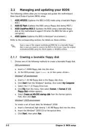
... of the following utilities allow you need to restore the BIOS in the future. b. 2.1 Managing and updating your BIOS The following methods to the optical drive. ASUS AFUDOS (Updates the BIOS in Windows® environment.) Refer to the floppy disk drive. ASUS CrashFree BIOS 2 (Updates the BIOS using a bootable floppy disk.) 2. DOS environment a. Insert a 1.44MB...
... of the following utilities allow you need to restore the BIOS in the future. b. 2.1 Managing and updating your BIOS The following methods to the optical drive. ASUS AFUDOS (Updates the BIOS in Windows® environment.) Refer to the floppy disk drive. ASUS CrashFree BIOS 2 (Updates the BIOS using a bootable floppy disk.) 2. DOS environment a. Insert a 1.44MB...

Motherboard DIY Troubleshooting Guide
Page 49
...to a floppy disk, then restart the system. 3. Floppy found !" error message appears if there is not found in the drive. e. ASUS P5GV-MX 2-3 d. EZFlash starting BIOS update Checking for the motherboard and rename the file as P5GVMX.ROM. error message appears if the correct...64258;oppy disk. From the Open field, type D:\bootdisk\makeboot a: assuming that D: is found !" To update the BIOS using a DOS-based utility. Visit the ASUS website (www.asus.com) to go through the long process of booting from a floppy disk and using EZ Flash: 1. Press + during...
...to a floppy disk, then restart the system. 3. Floppy found !" error message appears if there is not found in the drive. e. ASUS P5GV-MX 2-3 d. EZFlash starting BIOS update Checking for the motherboard and rename the file as P5GVMX.ROM. error message appears if the correct...64258;oppy disk. From the Open field, type D:\bootdisk\makeboot a: assuming that D: is found !" To update the BIOS using a DOS-based utility. Visit the ASUS website (www.asus.com) to go through the long process of booting from a floppy disk and using EZ Flash: 1. Press + during...

Motherboard DIY Troubleshooting Guide
Page 50
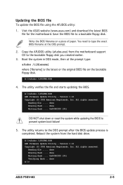
...updating process. Copy the AFUDOS utility (afudos.exe) from the motherboard support CD to the DOS prompt after copying the current BIOS file. 2-4 Chapter 2: BIOS setup A:\>afudos /oOLDBIOS1.ROM Main filename Extension name 3. done A:\> The utility returns to the bootable floppy disk you ...created earlier. 2. Copying the current BIOS To copy the current BIOS file using a bootable floppy disk with not more than eight alphanumeric characters in the main filename and...
...updating process. Copy the AFUDOS utility (afudos.exe) from the motherboard support CD to the DOS prompt after copying the current BIOS file. 2-4 Chapter 2: BIOS setup A:\>afudos /oOLDBIOS1.ROM Main filename Extension name 3. done A:\> The utility returns to the bootable floppy disk you ...created earlier. 2. Copying the current BIOS To copy the current BIOS file using a bootable floppy disk with not more than eight alphanumeric characters in the main filename and...
Motherboard DIY Troubleshooting Guide
Page 51
...;le on a piece of paper. Version 1.10 Copyright (C) 2002 American Megatrends, Inc. done Erasing flash .... done A:\> ASUS P5GV-MX 2-5 Visit the ASUS website (www.asus.com) and download the latest BIOS file for the motherboard. A:\>afudos /iP5GVMX.ROM 4. All rights reserved. Reading file ..... The utility returns to prevent system boot failure! 5. Save the...
...;le on a piece of paper. Version 1.10 Copyright (C) 2002 American Megatrends, Inc. done Erasing flash .... done A:\> ASUS P5GV-MX 2-5 Visit the ASUS website (www.asus.com) and download the latest BIOS file for the motherboard. A:\>afudos /iP5GVMX.ROM 4. All rights reserved. Reading file ..... The utility returns to prevent system boot failure! 5. Save the...
Motherboard DIY Troubleshooting Guide
Page 52
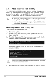
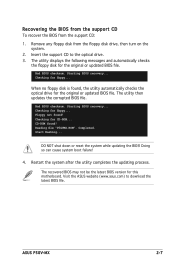
... the floppy disk as P5GVMX.ROM. Restart the system after the utility completes the updating process. 2-6 Chapter 2: BIOS setup Checking for the original or updated BIOS file. 2.1.4 ASUS CrashFree BIOS 2 utility The ASUS CrashFree BIOS 2 is an auto recovery tool that you to the floppy disk drive. 3. The utility displays the following message...
... the floppy disk as P5GVMX.ROM. Restart the system after the utility completes the updating process. 2-6 Chapter 2: BIOS setup Checking for the original or updated BIOS file. 2.1.4 ASUS CrashFree BIOS 2 utility The ASUS CrashFree BIOS 2 is an auto recovery tool that you to the floppy disk drive. 3. The utility displays the following message...
Motherboard DIY Troubleshooting Guide
Page 53
....ROM". DO NOT shut down or reset the system while updating the BIOS! Insert the support CD to download the latest BIOS file. Bad BIOS checksum. The utility then updates the corrupted BIOS file. Doing so can cause system boot failure! 4. ASUS P5GV-MX 2-7 CD-ROM found , the utility automatically checks the optical drive for...
....ROM". DO NOT shut down or reset the system while updating the BIOS! Insert the support CD to download the latest BIOS file. Bad BIOS checksum. The utility then updates the corrupted BIOS file. Doing so can cause system boot failure! 4. ASUS P5GV-MX 2-7 CD-ROM found , the utility automatically checks the optical drive for...
Motherboard DIY Troubleshooting Guide
Page 54
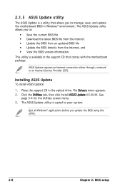
...in the support CD that allows you to your system. ASUS Update requires an Internet connection either through a network or an Internet Service Provider (ISP). The ASUS Update utility allows you update the BIOS using this utility. 2-8 Chapter 2: BIOS setup See page 3-4 for the Utilities screen menu. ...3. The Drivers menu appears. 2. Click the Utilities tab, then click Install ASUS Update VX.XX.XX. This utility is copied to manage, save, and update the motherboard BIOS in the optical drive. Place the support CD in Windows® environment. Quit all Windows®...
...in the support CD that allows you to your system. ASUS Update requires an Internet connection either through a network or an Internet Service Provider (ISP). The ASUS Update utility allows you update the BIOS using this utility. 2-8 Chapter 2: BIOS setup See page 3-4 for the Utilities screen menu. ...3. The Drivers menu appears. 2. Click the Utilities tab, then click Install ASUS Update VX.XX.XX. This utility is copied to manage, save, and update the motherboard BIOS in the optical drive. Place the support CD in Windows® environment. Quit all Windows®...


