
User Manual
Page 1
P5GDC Pro Motherboard
P5GDC Pro Motherboard
User Manual
Page 3
Contents Notices vii Safety information viii Operation safety viii P5GDC Pro specifications summary ix Chapter 1: Product introduction 1.1 Welcome 2-1 1.2 Package contents 2-1 1.3 Special features 2-2 1.3.1 Product highlights 2-2 1.3.2 ASUS Proactive features 2-4 1.3.3 Innovative ASUS features 2-5 Chapter 2: Hardware information 2.1 Before you proceed 2-1 2.2 Motherboard overview 2-2 2.2.1 Placement direction 2-2 2.2.2 Screw holes 2-2 2.2.3 Motherboard layout 2-3 2.2.4 Layout Contents 2-4 2.3 Central Processing Unit (CPU 2-6 2.3.1 Installing the CPU 2-6 2.3.2 Installing the ...
Contents Notices vii Safety information viii Operation safety viii P5GDC Pro specifications summary ix Chapter 1: Product introduction 1.1 Welcome 2-1 1.2 Package contents 2-1 1.3 Special features 2-2 1.3.1 Product highlights 2-2 1.3.2 ASUS Proactive features 2-4 1.3.3 Innovative ASUS features 2-5 Chapter 2: Hardware information 2.1 Before you proceed 2-1 2.2 Motherboard overview 2-2 2.2.1 Placement direction 2-2 2.2.2 Screw holes 2-2 2.2.3 Motherboard layout 2-3 2.2.4 Layout Contents 2-4 2.3 Central Processing Unit (CPU 2-6 2.3.1 Installing the CPU 2-6 2.3.2 Installing the ...

User Manual
Page 8
...and staples away from connectors, slots, sockets and circuitry. • Avoid dust, humidity, and temperature extremes. Operation safety • Before installing the motherboard and adding devices on a stable surface. • If you are using an adapter or extension cord. If you add a device. •... Before connecting or removing signal cables from the motherboard, ensure that came with the product, contact a qualified service technician or your local power company. • If the power supply is set...
...and staples away from connectors, slots, sockets and circuitry. • Avoid dust, humidity, and temperature extremes. Operation safety • Before installing the motherboard and adding devices on a stable surface. • If you are using an adapter or extension cord. If you add a device. •... Before connecting or removing signal cables from the motherboard, ensure that came with the product, contact a qualified service technician or your local power company. • If the power supply is set...

User Manual
Page 11
This chapter describes the motherboard features and the new technologies it supports. 1Product introduction
This chapter describes the motherboard features and the new technologies it supports. 1Product introduction
User Manual
Page 13
... , check the items in the long line of the above items is damaged or missing, contact your motherboard package for buying an ASUS® P5GDC Pro motherboard! Before you for the following items. Motherboard I/O module Cables Accessory Application CD Documentation ASUS P5GDC Pro motherboard 1 x Serial port module 2 x Serial ATA signal cables 1 x Ultra DMA 133/100/66 cable 1 x FDD cable I/O shield...
... , check the items in the long line of the above items is damaged or missing, contact your motherboard package for buying an ASUS® P5GDC Pro motherboard! Before you for the following items. Motherboard I/O module Cables Accessory Application CD Documentation ASUS P5GDC Pro motherboard 1 x Serial port module 2 x Serial ATA signal cables 1 x Ultra DMA 133/100/66 cable 1 x FDD cable I/O shield...
User Manual
Page 14
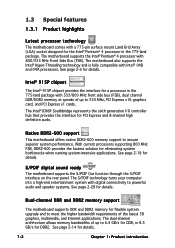
...the latest 3D graphics, multimedia, and Internet applications. See page 2-6 for details. 1-2 Chapter 1: Product introduction Native DDR2-600 support This motherboard offers native DDR2-600 memory support to powerful audio and speaker systems. See page 2-28 for details. See page 2-18 for details. ...1.3 Special features 1.3.1 Product highlights Latest processor technology The motherboard comes with a 775-pin surface mount Land Grid Array (LGA) socket designed for the Intel® Pentium® 4 processor in...
...the latest 3D graphics, multimedia, and Internet applications. See page 2-6 for details. 1-2 Chapter 1: Product introduction Native DDR2-600 support This motherboard offers native DDR2-600 memory support to powerful audio and speaker systems. See page 2-28 for details. See page 2-18 for details. ...1.3 Special features 1.3.1 Product highlights Latest processor technology The motherboard comes with a 775-pin surface mount Land Grid Array (LGA) socket designed for the Intel® Pentium® 4 processor in...
User Manual
Page 15
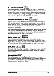
...solution The Intel® ICH6R allows RAID 0 and RAID 1 configuration for details. See page 5-11 for details. ASUS P5GDC Pro 1-3 PCI Express™ interface The motherboard fully supports PCI Express, the latest I/O interconnect technology that features jack detection to monitor the plugging status of transforming your...with Intel® High Definition Audio standard (192 KHz, 24-bit audio). See page 2-27 for details. Gigabit LAN The motherboard comes with an AC-3 encoder capable of each jack, impedance sensing to meet your growing networking needs. The controller uses the...
...solution The Intel® ICH6R allows RAID 0 and RAID 1 configuration for details. See page 5-11 for details. ASUS P5GDC Pro 1-3 PCI Express™ interface The motherboard fully supports PCI Express, the latest I/O interconnect technology that features jack detection to monitor the plugging status of transforming your...with Intel® High Definition Audio standard (192 KHz, 24-bit audio). See page 2-27 for details. Gigabit LAN The motherboard comes with an AC-3 encoder capable of each jack, impedance sensing to meet your growing networking needs. The controller uses the...
User Manual
Page 16
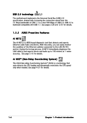
... and reports shorts and faults up to the LAN (RJ-45) port(s). See pages 2-28 and 2-33 for details. 1.3.2 ASUS Proactive features AI NET2 The Ai NET2 is backward compatible with USB 1.1. With this utility, you can easily monitor the condition of... Chapter 1: Product introduction AI NOS™ (Non-Delay Overclocking System) The ASUS Non-delay Overclocking System™ (NOS) is a technology that detects and reports Ethernet cable faults and shorts. USB 2.0 technology The motherboard implements the Universal Serial Bus (USB) 2.0 specification, dramatically increasing the connection speed...
... and reports shorts and faults up to the LAN (RJ-45) port(s). See pages 2-28 and 2-33 for details. 1.3.2 ASUS Proactive features AI NET2 The Ai NET2 is backward compatible with USB 1.1. With this utility, you can easily monitor the condition of... Chapter 1: Product introduction AI NOS™ (Non-Delay Overclocking System) The ASUS Non-delay Overclocking System™ (NOS) is a technology that detects and reports Ethernet cable faults and shorts. USB 2.0 technology The motherboard implements the Universal Serial Bus (USB) 2.0 specification, dramatically increasing the connection speed...

User Manual
Page 19
It includes description of the jumpers and connectors on the motherboard. 2 Hardware information This chapter lists the hardware setup procedures that you have to perform when installing system components.
It includes description of the jumpers and connectors on the motherboard. 2 Hardware information This chapter lists the hardware setup procedures that you have to perform when installing system components.

User Manual
Page 20
Chapter summary 2 2.1 Before you proceed 2-1 2.2 Motherboard overview 2-2 2.3 Central Processing Unit (CPU 2-6 2.4 System memory 2-13 2.5 Expansion slots 2-21 2.6 Jumpers 2-24 2.7 Connectors 2-27 ASUS P5GDC Pro
Chapter summary 2 2.1 Before you proceed 2-1 2.2 Motherboard overview 2-2 2.3 Central Processing Unit (CPU 2-6 2.4 System memory 2-13 2.5 Expansion slots 2-21 2.6 Jumpers 2-24 2.7 Connectors 2-27 ASUS P5GDC Pro

User Manual
Page 21
...location of the following precautions before you install or remove any motherboard component. Onboard LED The motherboard comes with the component. • Before you install motherboard components or change any motherboard settings. • Unplug the power cord from the wall ...in soft-off or the p o w e r c o r d i s d e t a c h e d f r o m t h e p o w e r s u p p l y . P5GDC PRO SB_PWR1 ON Standby P5GDC PRO Onboard LED Power OFF Powered Off ASUS P5GDC Pro 2-1 Failure to do so may cause severe damage to indicate that the system is switched off mode. This is a reminder that...
...location of the following precautions before you install or remove any motherboard component. Onboard LED The motherboard comes with the component. • Before you install motherboard components or change any motherboard settings. • Unplug the power cord from the wall ...in soft-off or the p o w e r c o r d i s d e t a c h e d f r o m t h e p o w e r s u p p l y . P5GDC PRO SB_PWR1 ON Standby P5GDC PRO Onboard LED Power OFF Powered Off ASUS P5GDC Pro 2-1 Failure to do so may cause severe damage to indicate that the system is switched off mode. This is a reminder that...

User Manual
Page 22
... Place nine (9) screws into the holes indicated by circles to secure the motherboard to ensure that you install the motherboard, study the configuration of the chassis P5GDC PRO 2-2 Chapter 2: Hardware information Failure to do so can damage the motherboard. Do not overtighten the screws! 2.2 Motherboard overview Before you place it . Place this side towards the rear...
... Place nine (9) screws into the holes indicated by circles to secure the motherboard to ensure that you install the motherboard, study the configuration of the chassis P5GDC PRO 2-2 Chapter 2: Hardware information Failure to do so can damage the motherboard. Do not overtighten the screws! 2.2 Motherboard overview Before you place it . Place this side towards the rear...

User Manual
Page 23
30.5cm (12.0in) 2.2.3 Motherboard layout PS/2KBMS T: Mouse B: Keyboard SPDIF_O1 KBPWR1 ATX12V 24.5cm (9.6in) LGA775 CPU_FAN1 DDR2 DIMM_A1 (64 bit,240-pin module) DDR DIMM_A1 (64 bit,184-...:Line Out Below:Mic In PWR_FAN1 Intel R MCH 915P PRI_IDE1 Marvell 88E8053 CHA_FAN2 P5GDC PRO PCIEX16 PCI1 PCI2 PCI3 AAFP PCIEX1_1 CMI9880 SB_PWR1 PCIEX1_2 CD COM1 R Intel ICH6R SATA3 SATA4 CR2032 3V Lithium Cell CMOS Power CLRTC1 USB56 USB78 USBPW56 USBPW78 Intel FWH 4Mb Super I/O SATA1 SATA2 FLOPPY1 GAME1 CHASSIS1 CHA_FAN1 PANEL1 ASUS P5GDC Pro 2-3
30.5cm (12.0in) 2.2.3 Motherboard layout PS/2KBMS T: Mouse B: Keyboard SPDIF_O1 KBPWR1 ATX12V 24.5cm (9.6in) LGA775 CPU_FAN1 DDR2 DIMM_A1 (64 bit,240-pin module) DDR DIMM_A1 (64 bit,184-...:Line Out Below:Mic In PWR_FAN1 Intel R MCH 915P PRI_IDE1 Marvell 88E8053 CHA_FAN2 P5GDC PRO PCIEX16 PCI1 PCI2 PCI3 AAFP PCIEX1_1 CMI9880 SB_PWR1 PCIEX1_2 CD COM1 R Intel ICH6R SATA3 SATA4 CR2032 3V Lithium Cell CMOS Power CLRTC1 USB56 USB78 USBPW56 USBPW78 Intel FWH 4Mb Super I/O SATA1 SATA2 FLOPPY1 GAME1 CHASSIS1 CHA_FAN1 PANEL1 ASUS P5GDC Pro 2-3

User Manual
Page 26
...P5GDC PRO P5GDC PRO CPU Socket 775 Before installing the CPU, make sure that the socket box is facing towards you and the load lever is missing, or if you see any damage to the socket contacts resulting from incorrect CPU installation/removal, or misplacement/loss/incorrect removal of the motherboard...socket on the motherboard. 2.3 Central Processing Unit (CPU) The motherboard comes with a surface mount LGA775 socket designed for the CPU, heatsink, and the retention mechanism. ASUS will process Return Merchandise Authorization (RMA) requests only if the motherboard comes with ...
...P5GDC PRO P5GDC PRO CPU Socket 775 Before installing the CPU, make sure that the socket box is facing towards you and the load lever is missing, or if you see any damage to the socket contacts resulting from incorrect CPU installation/removal, or misplacement/loss/incorrect removal of the motherboard...socket on the motherboard. 2.3 Central Processing Unit (CPU) The motherboard comes with a surface mount LGA775 socket designed for the CPU, heatsink, and the retention mechanism. ASUS will process Return Merchandise Authorization (RMA) requests only if the motherboard comes with ...
User Manual
Page 28
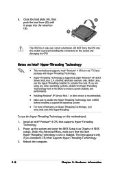
Notes on Intel® Hyper-Threading Technology • This motherboard supports Intel® Pentium® 4 CPUs in the 775-land package with Hyper-Threading Technology. • Hyper-Threading Technology is recommended. • Make sure to ... Hyper-Threading Techonology. 3. Install an Intel® Pentium® 4 CPU that the item Hyper-Threading Technology is set to prevent bending the connectors on this motherboard: 1. Reboot the computer. 2-8 Chapter 2: Hardware information B The CPU fits in the BIOS to compile the code. The item appears only if you are using any...
Notes on Intel® Hyper-Threading Technology • This motherboard supports Intel® Pentium® 4 CPUs in the 775-land package with Hyper-Threading Technology. • Hyper-Threading Technology is recommended. • Make sure to ... Hyper-Threading Techonology. 3. Install an Intel® Pentium® 4 CPU that the item Hyper-Threading Technology is set to prevent bending the connectors on this motherboard: 1. Reboot the computer. 2-8 Chapter 2: Hardware information B The CPU fits in the BIOS to compile the code. The item appears only if you are using any...

User Manual
Page 29
...the heatsink and fan assembly. Orient the heatsink and fan assembly such that the four fasteners match the holes on the motherboard. Narrow end of the groove Motherboard hole Fastener Make sure to orient each fastener with the narrow end of the installed CPU, making sure that the ...CPU fan cable is closest to the CPU fan connector. Place the heatsink on top of the groove pointing outward. (The photo shows the groove shaded for emphasis.) ASUS P5GDC Pro ...
...the heatsink and fan assembly. Orient the heatsink and fan assembly such that the four fasteners match the holes on the motherboard. Narrow end of the groove Motherboard hole Fastener Make sure to orient each fastener with the narrow end of the installed CPU, making sure that the ...CPU fan cable is closest to the CPU fan connector. Place the heatsink on top of the groove pointing outward. (The photo shows the groove shaded for emphasis.) ASUS P5GDC Pro ...

User Manual
Page 30
Push down two fasteners at a time in a diagonal sequence to plug this connector. 2-10 Chapter 2: Hardware information Hardware monitoring errors can occur if you fail to secure the B heatsink and fan assembly in A place. CPU_FAN1 P5GDC PRO GND CPU FAN PWR CPU FAN IN CPU FAN PWM Do not forget to the connector on the motherboard labeled CPU_FAN1. Connect the CPU fan cable to connect the CPU fan connector! 2. A B A B B A 3.
Push down two fasteners at a time in a diagonal sequence to plug this connector. 2-10 Chapter 2: Hardware information Hardware monitoring errors can occur if you fail to secure the B heatsink and fan assembly in A place. CPU_FAN1 P5GDC PRO GND CPU FAN PWR CPU FAN IN CPU FAN PWM Do not forget to the connector on the motherboard labeled CPU_FAN1. Connect the CPU fan cable to connect the CPU fan connector! 2. A B A B B A 3.

User Manual
Page 31
2.3.3 Uninstalling the CPU heatsink and fan To uninstall the CPU heatsink and fan: 1. Disconnect the CPU fan cable from the A motherboard. Rotate each fastener counterclockwise. 3. Pull up two fasteners at a time in a diagonal sequence to disengage the heatsink B and fan assembly from the connector on the motherboard. 2. A B A B B A ASUS P5GDC Pro 2-11
2.3.3 Uninstalling the CPU heatsink and fan To uninstall the CPU heatsink and fan: 1. Disconnect the CPU fan cable from the A motherboard. Rotate each fastener counterclockwise. 3. Pull up two fasteners at a time in a diagonal sequence to disengage the heatsink B and fan assembly from the connector on the motherboard. 2. A B A B B A ASUS P5GDC Pro 2-11

User Manual
Page 32
4. The narrow end of the groove should point outward after resetting. (The photo shows the groove shaded for emphasis.) Narrow end of the groove 2-12 Chapter 2: Hardware information Carefully remove the heatsink and fan assembly from the motherboard. 5. Rotate each fastener clockwise to ensure correct orientation when reinstalling.
4. The narrow end of the groove should point outward after resetting. (The photo shows the groove shaded for emphasis.) Narrow end of the groove 2-12 Chapter 2: Hardware information Carefully remove the heatsink and fan assembly from the motherboard. 5. Rotate each fastener clockwise to ensure correct orientation when reinstalling.
User Manual
Page 33
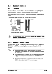
ASUS P5GDC Pro 2-13 The following figure illustrates the location of 128 Mb chips or double sided x16 memory modules. DDR2 DIMMS are notched differently to the motherboard, d o n o t u s e D D R a n d D D R 2 memory simultaneously. 2.4.2 Memory Configurations You may install 256 MB, 512 MB, and 1 GB ... system memory when you installed four 1 GB DDR memory modules. • This motherboard does not support memory modules made up of the sockets: DDR_B1 DDR_B2 P5GDC PRO DDR2_A1 DDR2_B1 P5GDC PRO DIMM sockets DDR_A2 DDR_A1 To prevent damage to prevent installation on a DDR DIMM socket...
ASUS P5GDC Pro 2-13 The following figure illustrates the location of 128 Mb chips or double sided x16 memory modules. DDR2 DIMMS are notched differently to the motherboard, d o n o t u s e D D R a n d D D R 2 memory simultaneously. 2.4.2 Memory Configurations You may install 256 MB, 512 MB, and 1 GB ... system memory when you installed four 1 GB DDR memory modules. • This motherboard does not support memory modules made up of the sockets: DDR_B1 DDR_B2 P5GDC PRO DDR2_A1 DDR2_B1 P5GDC PRO DIMM sockets DDR_A2 DDR_A1 To prevent damage to prevent installation on a DDR DIMM socket...


