Motherboard Installation Guide
Page 14
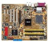
...CPU_FAN1 Intel FWH 8Mbit Super I/O FLOPPY1 DDR2 DIMM_B2 (64 bit,240-pin module) DDR2 DIMM_B1 (64 bit,240-pin module) P5GD2 DDR2 DIMM_A1 (64 bit,240-pin module) DDR2 DIMM_A2 (64 bit,240-pin module) SPDIF_O2 PARALLEL PORT KB1 USBPW34 USBPW12 ...RESET PWR * Requires an ATX power supply. Intel® Pentium® 4 в 775 1 язычок A PnP B 14 ASUS P5GD2 Deluxe усский KBPWR1 12 23 +5V +5VSB (Default) USBPW12 USBPW34 2 1 +5V (Default) 3 2 +5VSB USBPW56 USBPW78 12 23...
...CPU_FAN1 Intel FWH 8Mbit Super I/O FLOPPY1 DDR2 DIMM_B2 (64 bit,240-pin module) DDR2 DIMM_B1 (64 bit,240-pin module) P5GD2 DDR2 DIMM_A1 (64 bit,240-pin module) DDR2 DIMM_A2 (64 bit,240-pin module) SPDIF_O2 PARALLEL PORT KB1 USBPW34 USBPW12 ...RESET PWR * Requires an ATX power supply. Intel® Pentium® 4 в 775 1 язычок A PnP B 14 ASUS P5GD2 Deluxe усский KBPWR1 12 23 +5V +5VSB (Default) USBPW12 USBPW34 2 1 +5V (Default) 3 2 +5VSB USBPW56 USBPW78 12 23...
P5GD2 Deluxe user's manual
Page 17
... the items in the long line of the above items is damaged or missing, contact your retailer. 1.1 Welcome! Before you for the following items. Motherboard ASUS P5GD2 Deluxe motherboard I/O modules Serial port module (COM port) IEEE 1394 (1 port) module USB 2.0 (2 ports) and GAME (1 port) module Cables 6 x Serial ATA signal cables 3 x Serial ATA power...
... the items in the long line of the above items is damaged or missing, contact your retailer. 1.1 Welcome! Before you for the following items. Motherboard ASUS P5GD2 Deluxe motherboard I/O modules Serial port module (COM port) IEEE 1394 (1 port) module USB 2.0 (2 ports) and GAME (1 port) module Cables 6 x Serial ATA signal cables 3 x Serial ATA power...

P5GD2 Deluxe user's manual
Page 19
... SATA connectors and supports the Intel® Matrix Storage Technology. The CMI9880 CODEC comes with existing PCI specifications. See page 2-22 and 2-23 for details. ASUS P5GD2 Deluxe 1-3 See pages 2-27 and 5-17 for details. PCI Express features point-to an AC-3 or DTS decoder for two IDE channels that speeds up to...
... SATA connectors and supports the Intel® Matrix Storage Technology. The CMI9880 CODEC comes with existing PCI specifications. See page 2-22 and 2-23 for details. ASUS P5GD2 Deluxe 1-3 See pages 2-27 and 5-17 for details. PCI Express features point-to an AC-3 or DTS decoder for two IDE channels that speeds up to...
P5GD2 Deluxe user's manual
Page 21
...PCB under the motherboard CPU socket, Stack Cool effectively lowers the system temperature by large capacitors and motherboard components. ASUS P5GD2 Deluxe 1-5 Cooler system temperature means more stable system performance, longer component life, and more silent operation. AI NOS™ (Non-...Delay Overclocking System) ASUS Non-delay Overclocking System™ (NOS) is an ideal thermal solution that reduces the heat dissipated by 10º Celsius. 1.3.2 ASUS Proactive features ASUS Stack Cool ASUS Stack Cool is a technology that auto-detects the ...
...PCB under the motherboard CPU socket, Stack Cool effectively lowers the system temperature by large capacitors and motherboard components. ASUS P5GD2 Deluxe 1-5 Cooler system temperature means more stable system performance, longer component life, and more silent operation. AI NOS™ (Non-...Delay Overclocking System) ASUS Non-delay Overclocking System™ (NOS) is an ideal thermal solution that reduces the heat dissipated by 10º Celsius. 1.3.2 ASUS Proactive features ASUS Stack Cool ASUS Stack Cool is a technology that auto-detects the ...

P5GD2 Deluxe user's manual
Page 24
Chapter summary 2.1 Before you proceed 2-1 2.2 Motherboard overview 2-2 2.3 Central Processing Unit (CPU 2-7 2.4 System memory 2-13 2.5 Expansion slots 2-16 2.6 Jumpers 2-19 2.7 Connectors 2-22 ASUS P5GD2 Deluxe
Chapter summary 2.1 Before you proceed 2-1 2.2 Motherboard overview 2-2 2.3 Central Processing Unit (CPU 2-7 2.4 System memory 2-13 2.5 Expansion slots 2-16 2.6 Jumpers 2-19 2.7 Connectors 2-22 ASUS P5GD2 Deluxe
P5GD2 Deluxe user's manual
Page 25
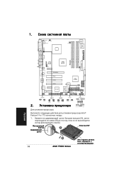
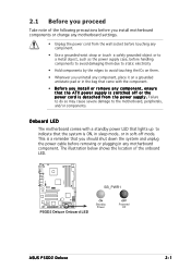
..., or in the bag that came with a standby power LED that lights up to the motherboard, peripherals, and/or components. P5GD2 ® SB_PWR1 P5GD2 Deluxe Onboard LED ON Standby Power OFF Powered Off ASUS P5GD2 Deluxe 2-1 The illustration below shows the location of the following precautions before you install motherboard components or change any motherboard settings...
..., or in the bag that came with a standby power LED that lights up to the motherboard, peripherals, and/or components. P5GD2 ® SB_PWR1 P5GD2 Deluxe Onboard LED ON Standby Power OFF Powered Off ASUS P5GD2 Deluxe 2-1 The illustration below shows the location of the following precautions before you install motherboard components or change any motherboard settings...
P5GD2 Deluxe user's manual
Page 27
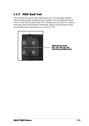
Motherboard holes (for the CPU fan and heatsink assembly pins) ASUS P5GD2 Deluxe 2-3 Stack Cool is a mini-PCB installed under the motherboard CPU socket to the motherboard. Stack Cool effectively lowers the motherboard temperature by as much as 10ºC. 2.2.3 ASUS Stack Cool The motherboard comes with ASUS Stack Cool, an innovative thermal solution that provides supplementary cooling to conduct heat away from motherboard components.
Motherboard holes (for the CPU fan and heatsink assembly pins) ASUS P5GD2 Deluxe 2-3 Stack Cool is a mini-PCB installed under the motherboard CPU socket to the motherboard. Stack Cool effectively lowers the motherboard temperature by as much as 10ºC. 2.2.3 ASUS Stack Cool The motherboard comes with ASUS Stack Cool, an innovative thermal solution that provides supplementary cooling to conduct heat away from motherboard components.
P5GD2 Deluxe user's manual
Page 31
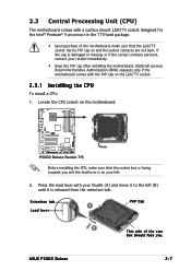
... left . 2. Retention tab A Load lever PnP Cap B This side of the motherboard, make sure that the LGA775 socket has its PnP cap on the motherboard. ASUS P5GD2 Deluxe 2-7 2.3 Central Processing Unit (CPU) The motherboard comes with the PnP cap on the LGA775 socket. 2.3.1 Installling the CPU To install a CPU: 1. If the cap ... and the socket contacts are bent, contact your thumb (A) and move it is damaged or missing, or if the socket contacts are not bent. P5GD2 ® P5GD2 Deluxe Socket 775 Before installing the CPU, make sure that the socket box is facing towards you .
... left . 2. Retention tab A Load lever PnP Cap B This side of the motherboard, make sure that the LGA775 socket has its PnP cap on the motherboard. ASUS P5GD2 Deluxe 2-7 2.3 Central Processing Unit (CPU) The motherboard comes with the PnP cap on the LGA775 socket. 2.3.1 Installling the CPU To install a CPU: 1. If the cap ... and the socket contacts are bent, contact your thumb (A) and move it is damaged or missing, or if the socket contacts are not bent. P5GD2 ® P5GD2 Deluxe Socket 775 Before installing the CPU, make sure that the socket box is facing towards you .
P5GD2 Deluxe user's manual
Page 33
....com/info/hyperthreading. Power up the system and enter the BIOS Setup (see Chapter 4: BIOS setup). If you installed a CPU that supports Hyper-Threading Technology. 3. ASUS P5GD2 Deluxe 2-9 Install an Intel® Pentium® 4 CPU that the item Hyper-Threading Technology is supported under Windows® XP/2003 Server and Linux 2.4.x (kernel) and...
....com/info/hyperthreading. Power up the system and enter the BIOS Setup (see Chapter 4: BIOS setup). If you installed a CPU that supports Hyper-Threading Technology. 3. ASUS P5GD2 Deluxe 2-9 Install an Intel® Pentium® 4 CPU that the item Hyper-Threading Technology is supported under Windows® XP/2003 Server and Linux 2.4.x (kernel) and...
P5GD2 Deluxe user's manual
Page 35
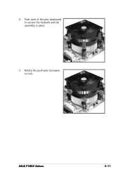
2. Push each of the pins downward to lock. Rotate the push-pins clockwise to secure the heatsink and fan assembly in place. 3. ASUS P5GD2 Deluxe 2-11
2. Push each of the pins downward to lock. Rotate the push-pins clockwise to secure the heatsink and fan assembly in place. 3. ASUS P5GD2 Deluxe 2-11
P5GD2 Deluxe user's manual
Page 37
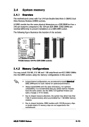
DDR2 DIMMs are not supported in this motherboard. The following figure illustrates the location of the sockets: P5GD2 DIMM_A1 DIMM_A2 DIMM_B1 DIMM_B2 ® P5GD2 Deluxe 184-Pin DDR DIMM sockets 2.4.2 Memory Configurations You may detect less than 4 GB of system memory when you ...into the DIMM sockets using the memory configurations in this section. • In dual-channel configurations, we recommend to the 184-pin DDR DIMM. ASUS P5GD2 Deluxe 2-13 See the DDR2 533 Qualified Vendors List (QVL) on a DDR DIMM socket. 2.4 System memory 2.4.1 Overview The motherboard comes with the...
DDR2 DIMMs are not supported in this motherboard. The following figure illustrates the location of the sockets: P5GD2 DIMM_A1 DIMM_A2 DIMM_B1 DIMM_B2 ® P5GD2 Deluxe 184-Pin DDR DIMM sockets 2.4.2 Memory Configurations You may detect less than 4 GB of system memory when you ...into the DIMM sockets using the memory configurations in this section. • In dual-channel configurations, we recommend to the 184-pin DDR DIMM. ASUS P5GD2 Deluxe 2-13 See the DDR2 533 Qualified Vendors List (QVL) on a DDR DIMM socket. 2.4 System memory 2.4.1 Overview The motherboard comes with the...
P5GD2 Deluxe user's manual
Page 39
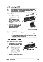
... DIMM. • The DDR2 DIMM sockets do so can cause severe damage to unlock the DIMM. Remove the DIMM from the socket. 2 1 DDR2 DIMM notch ASUS P5GD2 Deluxe 2-15 The DIMM might get 1 damaged when it fits in only one direction. Unlock a DIMM socket by pressing the retaining clips outward. 2. 2.4.3 Installing a DIMM Unplug...
... DIMM. • The DDR2 DIMM sockets do so can cause severe damage to unlock the DIMM. Remove the DIMM from the socket. 2 1 DDR2 DIMM notch ASUS P5GD2 Deluxe 2-15 The DIMM might get 1 damaged when it fits in only one direction. Unlock a DIMM socket by pressing the retaining clips outward. 2. 2.4.3 Installing a DIMM Unplug...

P5GD2 Deluxe user's manual
Page 41
... on shared slots, ensure that the drivers support "Share IRQ" or that the cards do not need IRQ assignments. shared shared - -- -- -- - - shared shared -- shared shared - ASUS P5GD2 Deluxe 2-17
... on shared slots, ensure that the drivers support "Share IRQ" or that the cards do not need IRQ assignments. shared shared - -- -- -- - - shared shared -- shared shared - ASUS P5GD2 Deluxe 2-17
P5GD2 Deluxe user's manual
Page 43
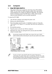
...Except when clearing the RTC RAM, never remove the cap on pins 2-3 for about 5~10 seconds, then move the cap back to re-enter data. ASUS P5GD2 Deluxe 2-19 You can automatically reset parameter settings to default values. Remove the onboard battery. 3. Plug the power cord and turn ON the computer. 6. Removing... and unplug the power cord. 2. Shut down the key during the boot process and enter BIOS setup to pins 1-2. 4. P5GD2 ® CLRTC1 12 23 Normal (Default) P5GD2 Deluxe Clear RTC RAM Clear CMOS You do not need to clear the RTC when the system hangs due to clear the Real...
...Except when clearing the RTC RAM, never remove the cap on pins 2-3 for about 5~10 seconds, then move the cap back to re-enter data. ASUS P5GD2 Deluxe 2-19 You can automatically reset parameter settings to default values. Remove the onboard battery. 3. Plug the power cord and turn ON the computer. 6. Removing... and unplug the power cord. 2. Shut down the key during the boot process and enter BIOS setup to pins 1-2. 4. P5GD2 ® CLRTC1 12 23 Normal (Default) P5GD2 Deluxe Clear RTC RAM Clear CMOS You do not need to clear the RTC when the system hangs due to clear the Real...

P5GD2 Deluxe user's manual
Page 45
3. Set this jumper to wake up feature. This feature requires an ATX power supply that can supply at least 1A on the keyboard (the default is the Space Bar). KBPWR1 12 23 +5V +5VSB (Default) P5GD2 P5GD2 Deluxe Keyboard power setting ASUS P5GD2 Deluxe 2-21 Keyboard power (3-pin KBPWR1) This jumper allows you to enable or disable the keyboard wake-up the computer when you wish to pins 2-3 (+5VSB) if you press a key on the +5VSB lead, and a corresponding setting in the BIOS.
3. Set this jumper to wake up feature. This feature requires an ATX power supply that can supply at least 1A on the keyboard (the default is the Space Bar). KBPWR1 12 23 +5V +5VSB (Default) P5GD2 P5GD2 Deluxe Keyboard power setting ASUS P5GD2 Deluxe 2-21 Keyboard power (3-pin KBPWR1) This jumper allows you to enable or disable the keyboard wake-up the computer when you wish to pins 2-3 (+5VSB) if you press a key on the +5VSB lead, and a corresponding setting in the BIOS.
P5GD2 Deluxe user's manual
Page 47
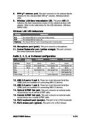
...) 9 . This port connects an external audio output device via an optical S/PDIF cable. 1 5 . This port is transmitting and/or receiving data. 1 0 . This port connects a microphone. 1 1 . U S B 2 . 0 p o r t s 1 a n d 2 . O p t i c a l S / P D I F O u t p o r t . P S / 2 k e y b o a r d p o r t ( p u r p l e ) . ASUS P5GD2 Deluxe 2-23 C e n t e r / S u b w o o f e r p o r t ( y e l l o w o r a n g e ) . This port connects the center/subwoofer speakers. Refer to the optional dipolar antenna for connecting USB 2.0 devices. 1 3 . The onboard WiFi-g™ card is for...
...) 9 . This port connects an external audio output device via an optical S/PDIF cable. 1 5 . This port is transmitting and/or receiving data. 1 0 . This port connects a microphone. 1 1 . U S B 2 . 0 p o r t s 1 a n d 2 . O p t i c a l S / P D I F O u t p o r t . P S / 2 k e y b o a r d p o r t ( p u r p l e ) . ASUS P5GD2 Deluxe 2-23 C e n t e r / S u b w o o f e r p o r t ( y e l l o w o r a n g e ) . This port connects the center/subwoofer speakers. Refer to the optional dipolar antenna for connecting USB 2.0 devices. 1 3 . The onboard WiFi-g™ card is for...

P5GD2 Deluxe user's manual
Page 49
These connectors are for Ultra ATA 133/100/66 signal cables. P5GD2 Deluxe RAID connectors • Before creating a RAID set using these connectors such as a disk array through the onboard IDE RAID controller. P5GD2 3 . Refer to set the I T E 8 2 1 2 F C o n t r o l l e r item in the BIOS to RAID Mode. See ...by default. SEC_RAID1 PIN 1 R PRI_RAID1 PIN 1 NOTE: Orient the red markings (usually zigzag) on how to Chapter 5 for details. ASUS P5GD2 Deluxe 2-25 In IDE mode, you have connected the Ultra ATA signal cable and installed Ultra ATA 133/100/66 hard disk drives. •...
These connectors are for Ultra ATA 133/100/66 signal cables. P5GD2 Deluxe RAID connectors • Before creating a RAID set using these connectors such as a disk array through the onboard IDE RAID controller. P5GD2 3 . Refer to set the I T E 8 2 1 2 F C o n t r o l l e r item in the BIOS to RAID Mode. See ...by default. SEC_RAID1 PIN 1 R PRI_RAID1 PIN 1 NOTE: Orient the red markings (usually zigzag) on how to Chapter 5 for details. ASUS P5GD2 Deluxe 2-25 In IDE mode, you have connected the Ultra ATA signal cable and installed Ultra ATA 133/100/66 hard disk drives. •...
P5GD2 Deluxe user's manual
Page 51
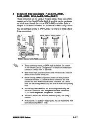
...drives to any of these connectors. GND RSATA_TXP2 RSATA_TXN2 GND RSATA_RXP2 RSATA_RXN2 GND GND RSATA_TXP4 RSATA_TXN4 GND RSATA_RXP4 RSATA_RXN4 GND P5GD2 GND RSATA_TXP1 RSATA_TXN1 GND RSATA_RXP1 RSATA_RXN1 GND GND RSATA_TXP3 RSATA_TXN3 GND RSATA_RXP3 RSATA_RXN3 GND 5 . These connectors support up Serial...ATA signal cables. SATA_RAID2 SATA_RAID4 ® SATA_RAID1 SATA_RAID3 P5GD2 Deluxe SATA RAID connectors • These connectors are set up to any of these connectors and have installed the Serial ATA hard disks drives; ASUS P5GD2 Deluxe 2-27 You can be configured as a disk array...
...drives to any of these connectors. GND RSATA_TXP2 RSATA_TXN2 GND RSATA_RXP2 RSATA_RXN2 GND GND RSATA_TXP4 RSATA_TXN4 GND RSATA_RXP4 RSATA_RXN4 GND P5GD2 GND RSATA_TXP1 RSATA_TXN1 GND RSATA_RXP1 RSATA_RXN1 GND GND RSATA_TXP3 RSATA_TXN3 GND RSATA_RXP3 RSATA_RXN3 GND 5 . These connectors support up Serial...ATA signal cables. SATA_RAID2 SATA_RAID4 ® SATA_RAID1 SATA_RAID3 P5GD2 Deluxe SATA RAID connectors • These connectors are set up to any of these connectors and have installed the Serial ATA hard disks drives; ASUS P5GD2 Deluxe 2-27 You can be configured as a disk array...
P5GD2 Deluxe user's manual
Page 53
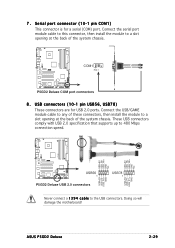
Serial port connector (10-1 pin COM1) This connector is for USB 2.0 ports. ASUS P5GD2 Deluxe 2-29 Connect the serial port module cable to this connector, then install the module to a slot opening at the back of ...chassis. Doing so will damage the motherboard! P5GD2 USB+5V USB_P8USB_P8+ GND NC USB+5V USB_P6USB_P6+ GND NC ® USB+5V USB_P7USB_P7+ GND USB+5V USB_P5USB_P5+ GND USB56 1 P5GD2 Deluxe USB 2.0 connectors USB78 1 Never connect a 1 3 9 4 c a b l e to 480 Mbps connection speed. P5GD2 COM1 ® PIN 1 P5GD2 Deluxe COM port connectors 8 . These USB ...
Serial port connector (10-1 pin COM1) This connector is for USB 2.0 ports. ASUS P5GD2 Deluxe 2-29 Connect the serial port module cable to this connector, then install the module to a slot opening at the back of ...chassis. Doing so will damage the motherboard! P5GD2 USB+5V USB_P8USB_P8+ GND NC USB+5V USB_P6USB_P6+ GND NC ® USB+5V USB_P7USB_P7+ GND USB+5V USB_P5USB_P5+ GND USB56 1 P5GD2 Deluxe USB 2.0 connectors USB78 1 Never connect a 1 3 9 4 c a b l e to 480 Mbps connection speed. P5GD2 COM1 ® PIN 1 P5GD2 Deluxe COM port connectors 8 . These USB ...
P5GD2 Deluxe user's manual
Page 55
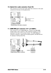
...; Right Audio Channel Ground Ground Left Audio Channel P5GD2 Deluxe CD audio connector 11. Connect the USB/GAME module cable to this connector, then install the module to the audio connector at the back of ... 4-pin audio cable that connects to a slot opening at the back of the system chassis. P5GD2 +5V J2B1 J2CX MIDI_OUT J2CY J2B2 MIDI_IN ® P5GD2 Deluxe Game connector GAME1 +5V J1B1 J1CX GND GND J1CY J1B2 +5V ASUS P5GD2 Deluxe 2-31 Optical drive audio connector (4-pin CD) This connector is for playing or editing audio files...
...; Right Audio Channel Ground Ground Left Audio Channel P5GD2 Deluxe CD audio connector 11. Connect the USB/GAME module cable to this connector, then install the module to the audio connector at the back of ... 4-pin audio cable that connects to a slot opening at the back of the system chassis. P5GD2 +5V J2B1 J2CX MIDI_OUT J2CY J2B2 MIDI_IN ® P5GD2 Deluxe Game connector GAME1 +5V J1B1 J1CX GND GND J1CY J1B2 +5V ASUS P5GD2 Deluxe 2-31 Optical drive audio connector (4-pin CD) This connector is for playing or editing audio files...


