
User Manual
Page 1
Motherboard P5G41TD-M PRO
Motherboard P5G41TD-M PRO

User Manual
Page 3
Contents Notices...vi Safety information vii About this guide vii P5G41TD-M PRO specifications summary ix Chapter 1: Product introduction 1.1 Welcome 1-1 1.2 Package contents 1-1 1.3 Special features 1-1 1.3.1 Product highlights 1-1 1.3.2 Innovative ASUS features 1-2 1.4 Before you proceed 1-4 1.5 Motherboard overview 1-5 1.5.1 Placement direction 1-5 1.5.2 Screw holes 1-5 1.5.3 Motherboard layout 1-6 1.5.4 Layout contents 1-6 1.6 Central Processing Unit (CPU 1-7 1.6.1 Installing the CPU 1-7 1.6.2 Installing the CPU heatsink and fan 1-10 1.6.3 Uninstalling...
Contents Notices...vi Safety information vii About this guide vii P5G41TD-M PRO specifications summary ix Chapter 1: Product introduction 1.1 Welcome 1-1 1.2 Package contents 1-1 1.3 Special features 1-1 1.3.1 Product highlights 1-1 1.3.2 Innovative ASUS features 1-2 1.4 Before you proceed 1-4 1.5 Motherboard overview 1-5 1.5.1 Placement direction 1-5 1.5.2 Screw holes 1-5 1.5.3 Motherboard layout 1-6 1.5.4 Layout contents 1-6 1.6 Central Processing Unit (CPU 1-7 1.6.1 Installing the CPU 1-7 1.6.2 Installing the CPU heatsink and fan 1-10 1.6.3 Uninstalling...
User Manual
Page 6
...assure compliance with manufacturer's instructions, may cause undesired operation. vi However, there is required to radio communications. DO NOT throw the motherboard in a particular installation. Check local regulations for connection of electronic products. Changes or modifications to this equipment. DO NOT throw the... designed to which can radiate radio frequency energy and, if not installed and used in our products at ASUS REACH website at http://green.asus.com/english/REACH.htm. This product has been designed to operate this unit not expressly approved by one or...
...assure compliance with manufacturer's instructions, may cause undesired operation. vi However, there is required to radio communications. DO NOT throw the motherboard in a particular installation. Check local regulations for connection of electronic products. Changes or modifications to this equipment. DO NOT throw the... designed to which can radiate radio frequency energy and, if not installed and used in our products at ASUS REACH website at http://green.asus.com/english/REACH.htm. This product has been designed to operate this unit not expressly approved by one or...

User Manual
Page 7
...following parts: • Chapter 1: Product introduction This chapter describes the features of the electrical outlet you are not sure about the voltage of the motherboard and the new technology it by yourself. vii If you are using, contact your power supply is set to fix it supports. • .... How this guide This user guide contains the information you add a device. • Before connecting or removing signal cables from the motherboard, ensure that all the manuals that all cables are correctly connected and the power cables are not damaged. Operation safety • Before installing ...
...following parts: • Chapter 1: Product introduction This chapter describes the features of the electrical outlet you are not sure about the voltage of the motherboard and the new technology it by yourself. vii If you are using, contact your power supply is set to fix it supports. • .... How this guide This user guide contains the information you add a device. • Before connecting or removing signal cables from the motherboard, ensure that all the manuals that all cables are correctly connected and the power cables are not damaged. Operation safety • Before installing ...
User Manual
Page 11
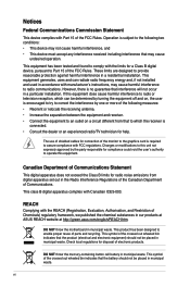
... enthusiastic gamers with the list below. 1.2 Package contents Check your motherboard package for the following items. Motherboard Cables Accessories Application DVD Documentation ASUS P5G41TD-M PRO motherboard 2 x Serial ATA cables 1 x Ultra DMA 100/66/33 cable 1 x I/O shield ASUS motherboard support DVD User Manual If any of ASUS quality motherboards! This motherboard also supports Intel® CPUs in the long line of the...
... enthusiastic gamers with the list below. 1.2 Package contents Check your motherboard package for the following items. Motherboard Cables Accessories Application DVD Documentation ASUS P5G41TD-M PRO motherboard 2 x Serial ATA cables 1 x Ultra DMA 100/66/33 cable 1 x I/O shield ASUS motherboard support DVD User Manual If any of ASUS quality motherboards! This motherboard also supports Intel® CPUs in the long line of the...

User Manual
Page 12
... moderating power in real-time. Serial ATA 3Gb/s technology This motherboard supports hard drives based on the Serial ATA (SATA) 3Gb/s storage specifications, delivering enhanced scalability and doubling the bus bandwidth for 3D graphics and other memory-demanding applications. ASUS Q-FAN ASUS Q-FAN technology intelligently and automatically adjusts CPU fan speed according to...
... moderating power in real-time. Serial ATA 3Gb/s technology This motherboard supports hard drives based on the Serial ATA (SATA) 3Gb/s storage specifications, delivering enhanced scalability and doubling the bus bandwidth for 3D graphics and other memory-demanding applications. ASUS Q-FAN ASUS Q-FAN technology intelligently and automatically adjusts CPU fan speed according to...

User Manual
Page 13
... restores the CPU default settings when the system hangs due to open the system chassis and clear the RTC data. ASUS P5G41TD-M PRO 1-3 eliminates the need to overclocking failure. ASUS Express Gate Express Gate is an auto-recovery tool that allows you to restore a corrupted BIOS file using the bundled... an OS-based utility. When installing it on USB HDDs or flash drives, connect the drives to the motherboard USB port before entering the Windows® OS. • ASUS Express Gate supports installation on SATA HDDs, USB HDDs and flash drives with the European Union's Restriction on ...
... restores the CPU default settings when the system hangs due to open the system chassis and clear the RTC data. ASUS P5G41TD-M PRO 1-3 eliminates the need to overclocking failure. ASUS Express Gate Express Gate is an auto-recovery tool that allows you to restore a corrupted BIOS file using the bundled... an OS-based utility. When installing it on USB HDDs or flash drives, connect the drives to the motherboard USB port before entering the Windows® OS. • ASUS Express Gate supports installation on SATA HDDs, USB HDDs and flash drives with the European Union's Restriction on ...

User Manual
Page 14
...; Before you install or remove any component, ensure that the system is detached from the wall socket before removing or plugging in any motherboard component. Failure to do so may cause severe damage to indicate that the ATX power supply is switched off or the power cord is... ON, in sleep mode, or in soft-off mode. The illustration below shows the location of the following precautions before you install motherboard components or change any motherboard settings. • Unplug the power cord from the power supply. 1.4 Before you proceed Take note of the onboard LED. 1-4 Chapter...
...; Before you install or remove any component, ensure that the system is detached from the wall socket before removing or plugging in any motherboard component. Failure to do so may cause severe damage to indicate that the ATX power supply is switched off or the power cord is... ON, in sleep mode, or in soft-off mode. The illustration below shows the location of the following precautions before you install motherboard components or change any motherboard settings. • Unplug the power cord from the power supply. 1.4 Before you proceed Take note of the onboard LED. 1-4 Chapter...

User Manual
Page 15
... side towards the rear of the chassis ASUS P5G41TD-M PRO 1-5 Doing so can cause you physical injury and damage motherboard components. 1.5.1 Placement direction When installing the motherboard, ensure that you unplug the power cord before installing or removing the motherboard. Ensure that you place it . 1.5 Motherboard overview Before you install the motherboard, study the configuration of your chassis...
... side towards the rear of the chassis ASUS P5G41TD-M PRO 1-5 Doing so can cause you physical injury and damage motherboard components. 1.5.1 Placement direction When installing the motherboard, ensure that you unplug the power cord before installing or removing the motherboard. Ensure that you place it . 1.5 Motherboard overview Before you install the motherboard, study the configuration of your chassis...

User Manual
Page 17
... cap. ASUS will shoulder the cost of repair only if the damage is on the motherboard. Locate the CPU socket on your left. ASUS will process Return Merchandise Authorization (RMA) requests only if the motherboard comes with... the Intel® Enhanced Intel SpeedStep® Technology (EIST) and Hyper-Threading Technology. 1.6.1 Installing the CPU To install a CPU: 1. Contact your retailer immediately if the PnP cap is missing, or if you and the load lever is shipment/transit-related. • Keep the cap after installing the motherboard. ASUS P5G41TD-M PRO...
... cap. ASUS will shoulder the cost of repair only if the damage is on the motherboard. Locate the CPU socket on your left. ASUS will process Return Merchandise Authorization (RMA) requests only if the motherboard comes with... the Intel® Enhanced Intel SpeedStep® Technology (EIST) and Hyper-Threading Technology. 1.6.1 Installing the CPU To install a CPU: 1. Contact your retailer immediately if the PnP cap is missing, or if you and the load lever is shipment/transit-related. • Keep the cap after installing the motherboard. ASUS P5G41TD-M PRO...

User Manual
Page 20
... a boxed Intel® processor, the package includes the CPU fan and heatsink assembly. Orient the heatsink and fan assembly such that you have installed the motherboard to the CPU heatsink or CPU before you install the heatsink and fan assembly. A B A B B A 1 1 B A The type of the installed CPU, ensuring that you have properly... on top of CPU heatsink and fan assembly may differ, but the installation steps and functions should remain the same. Place the heatsink on the motherboard. The illustration above is closest to secure the heatsink and fan assembly in place.
... a boxed Intel® processor, the package includes the CPU fan and heatsink assembly. Orient the heatsink and fan assembly such that you have installed the motherboard to the CPU heatsink or CPU before you install the heatsink and fan assembly. A B A B B A 1 1 B A The type of the installed CPU, ensuring that you have properly... on top of CPU heatsink and fan assembly may differ, but the installation steps and functions should remain the same. Place the heatsink on the motherboard. The illustration above is closest to secure the heatsink and fan assembly in place.

User Manual
Page 21
Disconnect the CPU fan cable from the motherboard. Pull up two fasteners at a time in a diagonal sequence to the connector on the motherboard. 2. A A B B B A B A ASUS P5G41TD-M PRO 1-11 Rotate each fastener counterclockwise. 3. 3. Do not forget to plug this connector. 1.6.3 Uninstalling the CPU heatsink and fan To uninstall the CPU heatsink and fan: 1. Connect the CPU fan cable to disengage the heatsink and fan assembly from the connector on the motherboard labeled CPU_FAN. Hardware monitoring errors can occur if you fail to connect the CPU fan connector!
Disconnect the CPU fan cable from the motherboard. Pull up two fasteners at a time in a diagonal sequence to the connector on the motherboard. 2. A A B B B A B A ASUS P5G41TD-M PRO 1-11 Rotate each fastener counterclockwise. 3. 3. Do not forget to plug this connector. 1.6.3 Uninstalling the CPU heatsink and fan To uninstall the CPU heatsink and fan: 1. Connect the CPU fan cable to disengage the heatsink and fan assembly from the connector on the motherboard labeled CPU_FAN. Hardware monitoring errors can occur if you fail to connect the CPU fan connector!

User Manual
Page 22
Rotate each fastener clockwise to ensure correct orientation when reinstalling. 1.7 System memory 1.7.1 Overview The motherboard comes with two Double Data Rate 3 (DDR3) Dual Inline Memory Modules (DIMM) sockets. Carefully remove the heatsink and fan assembly from the motherboard. 5. The figure illustrates the location of the DDR3 DIMM sockets: Channel Channel A Channel B Sockets DIMM_A1 DIMM_B1 1-12 Chapter 1: Product introduction 4.
Rotate each fastener clockwise to ensure correct orientation when reinstalling. 1.7 System memory 1.7.1 Overview The motherboard comes with two Double Data Rate 3 (DDR3) Dual Inline Memory Modules (DIMM) sockets. Carefully remove the heatsink and fan assembly from the motherboard. 5. The figure illustrates the location of the DDR3 DIMM sockets: Channel Channel A Channel B Sockets DIMM_A1 DIMM_B1 1-12 Chapter 1: Product introduction 4.

User Manual
Page 23
...; • • • • • • • ASUS P5G41TD-M PRO 1-13 Under the default state, some memory modules for the OS can be about 3GB or less. Install a 64-bit Windows® OS when you want to install 4GB or more memory on the motherboard. • This motherboard does not support DIMMs made up of...
...; • • • • • • • ASUS P5G41TD-M PRO 1-13 Under the default state, some memory modules for the OS can be about 3GB or less. Install a 64-bit Windows® OS when you want to install 4GB or more memory on the motherboard. • This motherboard does not support DIMMs made up of...

User Manual
Page 26
... until the retaining clips snap back in only one direction. DIMM notch 1-16 Chapter 1: Product introduction Firmly insert the DIMM into a socket to both the motherboard and the components. Remove the DIMM from the socket. Press the retaining clips outward to unlock the DIMM. 2 Support the DIMM lightly with extra force...
... until the retaining clips snap back in only one direction. DIMM notch 1-16 Chapter 1: Product introduction Firmly insert the DIMM into a socket to both the motherboard and the components. Remove the DIMM from the socket. Press the retaining clips outward to unlock the DIMM. 2 Support the DIMM lightly with extra force...
User Manual
Page 27
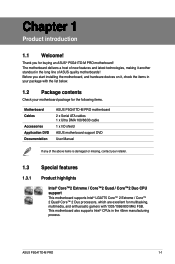
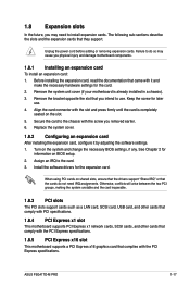
...software drivers for the card. 2. Failure to use . 4. See Chapter 2 for later use . When using PCI cards on the slot. 5. ASUS P5G41TD-M PRO 1-17 Remove the bracket opposite the slot that you intend to do not need to the card. 3. Align the card connector with it by adjusting... until the card is already installed in a chassis). 3. 1.8 Expansion slots In the future, you may cause you physical injury and damage motherboard components. 1.8.1 Installing an expansion card To install an expansion card: 1. Unplug the power cord before adding or removing expansion cards. Keep the...
...software drivers for the card. 2. Failure to use . 4. See Chapter 2 for later use . When using PCI cards on the slot. 5. ASUS P5G41TD-M PRO 1-17 Remove the bracket opposite the slot that you intend to do not need to the card. 3. Align the card connector with it by adjusting... until the card is already installed in a chassis). 3. 1.8 Expansion slots In the future, you may cause you physical injury and damage motherboard components. 1.8.1 Installing an expansion card To install an expansion card: 1. Unplug the power cord before adding or removing expansion cards. Keep the...

User Manual
Page 31
2. Insufficient air flow inside the system may damage the motherboard components. Only the 4-pin CPU fan supports the ASUS Q-FAN feature. 3. The S/PDIF module is for an additional Sony/Philips Digital Interface (S/PDIF) port. Connect the S/PDIF Out module cable to this connector, ...of the connector. Do not forget to connect the fan cables to the fan connectors on the fan connectors! ASUS P5G41TD-M PRO 1-21 These are not jumpers! Do not place jumper caps on the motherboard, ensuring that the black wire of each cable matches the ground pin of the system chassis. Digital audio ...
2. Insufficient air flow inside the system may damage the motherboard components. Only the 4-pin CPU fan supports the ASUS Q-FAN feature. 3. The S/PDIF module is for an additional Sony/Philips Digital Interface (S/PDIF) port. Connect the S/PDIF Out module cable to this connector, ...of the connector. Do not forget to connect the fan cables to the fan connectors on the fan connectors! ASUS P5G41TD-M PRO 1-21 These are not jumpers! Do not place jumper caps on the motherboard, ensuring that the black wire of each cable matches the ground pin of the system chassis. Digital audio ...

User Manual
Page 33
By default, this connector is faster than the standard parallel ATA with Serial ATA 1.5Gb/s specification. The data transfer rate of the motherboard's high-definition audio capability. • If you want to connect a high-definition front panel audio module to this connector, set the item ...are for the Serial ATA signal cables for details. 6. Install the Windows® XP Service Pack 2 or later version before using Serial ATA. ASUS P5G41TD-M PRO 1-23 If you want to connect an AC'97 front panel audio module to this connector, set to [AC97]. See section 2.4.3 Chipset for ...
By default, this connector is faster than the standard parallel ATA with Serial ATA 1.5Gb/s specification. The data transfer rate of the motherboard's high-definition audio capability. • If you want to connect a high-definition front panel audio module to this connector, set the item ...are for the Serial ATA signal cables for details. 6. Install the Windows® XP Service Pack 2 or later version before using Serial ATA. ASUS P5G41TD-M PRO 1-23 If you want to connect an AC'97 front panel audio module to this connector, set to [AC97]. See section 2.4.3 Chipset for ...

User Manual
Page 34
... 100/66/33 IDE devices. There are three connectors on the IDE connector is removed to configure your device. Connect the blue connector to the motherboard's IDE connector, then select one of device(s) Master Slave Master Slave Cable connector Black Black Gray Black or gray • Pin 20 on each Ultra...
... 100/66/33 IDE devices. There are three connectors on the IDE connector is removed to configure your device. Connect the blue connector to the motherboard's IDE connector, then select one of device(s) Master Slave Master Slave Cable connector Black Black Gray Black or gray • Pin 20 on each Ultra...

User Manual
Page 36
... (10-1 pin USB56, USB78) These connectors are for a serial (COM) port. Never connect a 1394 cable to 480 Mbps connection speed. Doing so will damage the motherboard! Connect the serial port module cable to the connector, then install the module to a slot opening at the back of the system chassis. Connect the...
... (10-1 pin USB56, USB78) These connectors are for a serial (COM) port. Never connect a 1394 cable to 480 Mbps connection speed. Doing so will damage the motherboard! Connect the serial port module cable to the connector, then install the module to a slot opening at the back of the system chassis. Connect the...


