User Manual
Page 11
.../1066/800MHz FSB. Before you for the following items. Motherboard Cables Accessories Application DVD Documentation ASUS P5G41T-M/USB3 motherboard 2 x Serial ATA cables 1 x Ultra DMA 100/66/33 cable 1 x I/O shield ASUS motherboard support DVD User Manual If any of ASUS quality motherboards! ASUS P5G41T-M/USB3 1-1 This motherboard also supports Intel® CPUs in the long line of the above...
.../1066/800MHz FSB. Before you for the following items. Motherboard Cables Accessories Application DVD Documentation ASUS P5G41T-M/USB3 motherboard 2 x Serial ATA cables 1 x Ultra DMA 100/66/33 cable 1 x I/O shield ASUS motherboard support DVD User Manual If any of ASUS quality motherboards! ASUS P5G41T-M/USB3 1-1 This motherboard also supports Intel® CPUs in the long line of the above...
User Manual
Page 13
... file uploading from SATA HDDs, ODDs and USB drives. ASUS CrashFree BIOS 3 ASUS CrashFree BIOS 3 is an ASUS exclusive OS, which lets you to work or games, simply through pressing the button. ASUS P5G41T-M/USB3 1-3 After easy setup, Turbo Key boosts performances without interrupting... ongoing work in real-time. It supports file downloading to save power and money. ASUS Anti-Surge Protection This special design prevents expensive ...
... file uploading from SATA HDDs, ODDs and USB drives. ASUS CrashFree BIOS 3 ASUS CrashFree BIOS 3 is an ASUS exclusive OS, which lets you to work or games, simply through pressing the button. ASUS P5G41T-M/USB3 1-3 After easy setup, Turbo Key boosts performances without interrupting... ongoing work in real-time. It supports file downloading to save power and money. ASUS Anti-Surge Protection This special design prevents expensive ...
User Manual
Page 15
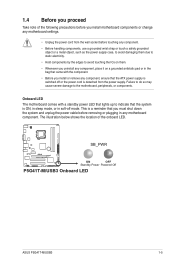
... to avoid touching the ICs on them. • Whenever you uninstall any component, place it on a grounded antistatic pad or in any motherboard component. SB_PWR P5G41T-M/USB3 ON OFF Standby Power Powered Off P5G41T-M/USB3 Onboard LED ASUS P5G41T-M/USB3 1-5
... to avoid touching the ICs on them. • Whenever you uninstall any component, place it on a grounded antistatic pad or in any motherboard component. SB_PWR P5G41T-M/USB3 ON OFF Standby Power Powered Off P5G41T-M/USB3 Onboard LED ASUS P5G41T-M/USB3 1-5
User Manual
Page 17
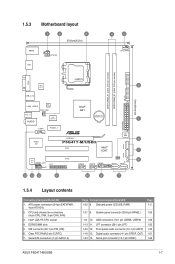
... Page Connectors/Jumpers/Slots/LED 1-22 8. System panel connector (20-8 pin PANEL) 1-25 1-8 10. Serial port connector (10-1 pin COM1) 1-26 ASUS P5G41T-M/USB3 1-7 DDR3 DIMM slots 5. 1.5.3 Motherboard layout 1 2 3 20.8cm(8.2in) KBMS ATX12V HDMI 4 2 CPU_FAN DDR3 DIMM_A1 (64bit, 240-pin module) DDR3...6in) LAN1_USB12 RTL 8111E CHA_FAN SPDIF_O2 AUDIO ICS 954 A4 COM1 PCIEX1_1 Intel® G41 Lithium Cell CMOS Power Super I/O PCIEX16 P5G41T-M/USB3 PCI1 Intel® ICH7 EATXPWR SATA4 1 8Mb BIOS 6 7 SATA2 ALC 887 SPDIF_OUT AAFP LPT PCI2 CLRTC 8 SB_PWR USB56 ...
... Page Connectors/Jumpers/Slots/LED 1-22 8. System panel connector (20-8 pin PANEL) 1-25 1-8 10. Serial port connector (10-1 pin COM1) 1-26 ASUS P5G41T-M/USB3 1-7 DDR3 DIMM slots 5. 1.5.3 Motherboard layout 1 2 3 20.8cm(8.2in) KBMS ATX12V HDMI 4 2 CPU_FAN DDR3 DIMM_A1 (64bit, 240-pin module) DDR3...6in) LAN1_USB12 RTL 8111E CHA_FAN SPDIF_O2 AUDIO ICS 954 A4 COM1 PCIEX1_1 Intel® G41 Lithium Cell CMOS Power Super I/O PCIEX16 P5G41T-M/USB3 PCI1 Intel® ICH7 EATXPWR SATA4 1 8Mb BIOS 6 7 SATA2 ALC 887 SPDIF_OUT AAFP LPT PCI2 CLRTC 8 SB_PWR USB56 ...
User Manual
Page 19
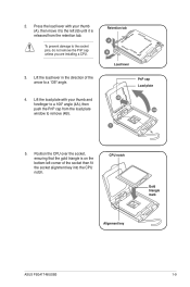
... your thumb and forefinger to a 100º angle (4A), then push the PnP cap from the retention tab. 2. CPU notch Gold triangle mark Alignment key ASUS P5G41T-M/USB3 1-9 Position the CPU over the socket, ensuring that the gold triangle is released from the load plate window to the socket pins, do not remove...
... your thumb and forefinger to a 100º angle (4A), then push the PnP cap from the retention tab. 2. CPU notch Gold triangle mark Alignment key ASUS P5G41T-M/USB3 1-9 Position the CPU over the socket, ensuring that the gold triangle is released from the load plate window to the socket pins, do not remove...
User Manual
Page 21
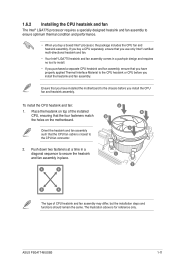
... fan and heatsink assembly. The illustration above is closest to ensure optimum thermal condition and performance. • When you install the heatsink and fan assembly. ASUS P5G41T-M/USB3 1-11 1.6.2 Installing the CPU heatsink and fan The Intel® LGA775 processor requires a specially designed heatsink and fan assembly to the CPU fan connector. 2. Place...
... fan and heatsink assembly. The illustration above is closest to ensure optimum thermal condition and performance. • When you install the heatsink and fan assembly. ASUS P5G41T-M/USB3 1-11 1.6.2 Installing the CPU heatsink and fan The Intel® LGA775 processor requires a specially designed heatsink and fan assembly to the CPU fan connector. 2. Place...
User Manual
Page 23
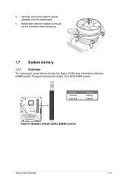
The figure illustrates the location of the DDR3 DIMM sockets: DIMM_A1 DIMM_B1 Channel Channel A Channel B Sockets DIMM_A1 DIMM_B1 P5G41T-M/USB3 P5G41T-M/USB3 240-pin DDR3 DIMM sockets ASUS P5G41T-M/USB3 1-13 Rotate each fastener clockwise to ensure correct orientation when reinstalling. 1.7 System memory 1.7.1 Overview The motherboard comes with two Double Data Rate 3 (DDR3) Dual Inline Memory Modules (DIMM) sockets. Carefully remove the heatsink and fan assembly from the motherboard. 5. 4.
The figure illustrates the location of the DDR3 DIMM sockets: DIMM_A1 DIMM_B1 Channel Channel A Channel B Sockets DIMM_A1 DIMM_B1 P5G41T-M/USB3 P5G41T-M/USB3 240-pin DDR3 DIMM sockets ASUS P5G41T-M/USB3 1-13 Rotate each fastener clockwise to ensure correct orientation when reinstalling. 1.7 System memory 1.7.1 Overview The motherboard comes with two Double Data Rate 3 (DDR3) Dual Inline Memory Modules (DIMM) sockets. Carefully remove the heatsink and fan assembly from the motherboard. 5. 4.

User Manual
Page 25
... for the latest QVL. Size SS/ Chip DS Brand Chip NO. DDR3-1333(O.C.) MHz capability Vendor Part No. ASUS P5G41T-M/USB3 1-15 DIMM socket CL Voltage support (Optional) A* B* A-Data AD31333001GOU 1024MB SS A-Data AD30908C8D-151C E0906 - - • • A-Data AD31333G001GOU 3072MB(Kit of 3) SS - - 8-8-8-24 1.65-1....
... for the latest QVL. Size SS/ Chip DS Brand Chip NO. DDR3-1333(O.C.) MHz capability Vendor Part No. ASUS P5G41T-M/USB3 1-15 DIMM socket CL Voltage support (Optional) A* B* A-Data AD31333001GOU 1024MB SS A-Data AD30908C8D-151C E0906 - - • • A-Data AD31333G001GOU 3072MB(Kit of 3) SS - - 8-8-8-24 1.65-1....
User Manual
Page 27
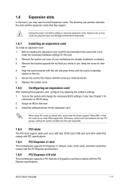
... slot This motherboard supports PCI Express x1 network cards, SCSI cards, and other cards that comply with the screw you intend to install expansion cards. ASUS P5G41T-M/USB3 1-17 Unplug the power cord before adding or removing expansion cards. Failure to do not need to use . 4. Assign an IRQ to the chassis with...
... slot This motherboard supports PCI Express x1 network cards, SCSI cards, and other cards that comply with the screw you intend to install expansion cards. ASUS P5G41T-M/USB3 1-17 Unplug the power cord before adding or removing expansion cards. Failure to do not need to use . 4. Assign an IRQ to the chassis with...
User Manual
Page 29
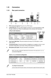
... 1.10.1 Rear panel connectors 1 2 34 11 10 9 8 7 65 1. PS/2 mouse port (green). Refer to the audio configuration table below for the LAN port LED indications. ASUS P5G41T-M/USB3 1-19 This port connects to the tape, CD, DVD player, or other audio sources. 4. This port is for the function of this port becomes Front...
... 1.10.1 Rear panel connectors 1 2 34 11 10 9 8 7 65 1. PS/2 mouse port (green). Refer to the audio configuration table below for the LAN port LED indications. ASUS P5G41T-M/USB3 1-19 This port connects to the tape, CD, DVD player, or other audio sources. 4. This port is for the function of this port becomes Front...
User Manual
Page 31
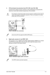
...the motherboard, ensuring that the black wire of each cable matches the ground pin of the system chassis. +5V SPDIFOUT GND P5G41T-M/USB3 SPDIF_OUT P5G41T-M/USB3 Digital audio connector The S/PDIF module is for an additional Sony/Philips Digital Interface (S/PDIF) port. CPU_FAN CPU FAN PWM ...) This connector is purchased separately. Do not forget to connect the fan cables to a slot opening at the back of the connector. ASUS P5G41T-M/USB3 1-21 2. Insufficient air flow inside the system may damage the motherboard components. CPU and chassis fan connectors (4-pin CPU_FAN, 3-pin CHA_FAN)...
...the motherboard, ensuring that the black wire of each cable matches the ground pin of the system chassis. +5V SPDIFOUT GND P5G41T-M/USB3 SPDIF_OUT P5G41T-M/USB3 Digital audio connector The S/PDIF module is for an additional Sony/Philips Digital Interface (S/PDIF) port. CPU_FAN CPU FAN PWM ...) This connector is purchased separately. Do not forget to connect the fan cables to a slot opening at the back of the connector. ASUS P5G41T-M/USB3 1-21 2. Insufficient air flow inside the system may damage the motherboard components. CPU and chassis fan connectors (4-pin CPU_FAN, 3-pin CHA_FAN)...
User Manual
Page 33
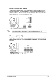
... GND GND GND GND GND STB# PD0 PD1 PD2 PD3 PD4 PD5 PD6 PD7 ACK# BUSY PE SLCT P5G41T-M/USB3 PIN 1 P5G41T-M/USB3 Parallel Port Connector ASUS P5G41T-M/USB3 1-23 LPT is standardized as a printer. The Serial ATA 3Gb/s is the parallel port interface on IBM...1.5Gb/s specification. GND RSATA_TXP4 RSATA_TXN4 GND SATA4 RSATA_RXP4 RSATA_RXN4 GND GND RSATA_TXP2 RSATA_TXN2 GND SATA2 RSATA_RXP2 RSATA_RXN2 GND P5G41T-M/USB3 SATA1 SATA3 P5G41T-M/USB3 SATA connectors GND RSATA_RXN1 RSATA_RXP1 GND RSATA_TXN1 RSATA_TXP1 GND GND RSATA_RXN3 RSATA_RXP3 GND RSATA_TXN3 RSATA_TXP3 GND Install the Windows...
... GND GND GND GND GND STB# PD0 PD1 PD2 PD3 PD4 PD5 PD6 PD7 ACK# BUSY PE SLCT P5G41T-M/USB3 PIN 1 P5G41T-M/USB3 Parallel Port Connector ASUS P5G41T-M/USB3 1-23 LPT is standardized as a printer. The Serial ATA 3Gb/s is the parallel port interface on IBM...1.5Gb/s specification. GND RSATA_TXP4 RSATA_TXN4 GND SATA4 RSATA_RXP4 RSATA_RXN4 GND GND RSATA_TXP2 RSATA_TXN2 GND SATA2 RSATA_RXP2 RSATA_RXN2 GND P5G41T-M/USB3 SATA1 SATA3 P5G41T-M/USB3 SATA connectors GND RSATA_RXN1 RSATA_RXP1 GND RSATA_TXN1 RSATA_TXP1 GND GND RSATA_RXN3 RSATA_RXP3 GND RSATA_TXN3 RSATA_TXP3 GND Install the Windows...

User Manual
Page 35
... button. • Reset button (2-pin RESET) This 2-pin connector is for the chassis-mounted system warning speaker. PWR Ground Reset Ground P5G41T-M/USB3 IDE_LED PWRSW RESET * Requires an ATX power supply P5G41T-M/USB3 System panel connector • System power LED (2-pin PLED) This 2-pin connector is for the HDD Activity LED. The system power... system power. System panel connector (20-8 pin PANEL) This connector supports several chassis-mounted functions. The IDE LED lights up when you to this connector. 8. ASUS P5G41T-M/USB3 1-25
... button. • Reset button (2-pin RESET) This 2-pin connector is for the chassis-mounted system warning speaker. PWR Ground Reset Ground P5G41T-M/USB3 IDE_LED PWRSW RESET * Requires an ATX power supply P5G41T-M/USB3 System panel connector • System power LED (2-pin PLED) This 2-pin connector is for the HDD Activity LED. The system power... system power. System panel connector (20-8 pin PANEL) This connector supports several chassis-mounted functions. The IDE LED lights up when you to this connector. 8. ASUS P5G41T-M/USB3 1-25
User Manual
Page 37
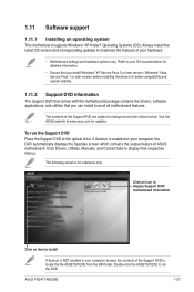
... for reference only. Click an icon to display Support DVD/ motherboard information Click an item to install If Autorun is for updates. ASUS P5G41T-M/USB3 1-27 Click Drivers, Utilities, Manuals, and Contact tabs to run the Support DVD Place the Support DVD to locate the file ASSETUP.EXE from... the BIN folder. Visit the ASUS website at any time without notice. The following screen is NOT enabled in your computer, browse the contents of your OS documentation for detailed ...
... for reference only. Click an icon to display Support DVD/ motherboard information Click an item to install If Autorun is for updates. ASUS P5G41T-M/USB3 1-27 Click Drivers, Utilities, Manuals, and Contact tabs to run the Support DVD Place the Support DVD to locate the file ASSETUP.EXE from... the BIN folder. Visit the ASUS website at any time without notice. The following screen is NOT enabled in your computer, browse the contents of your OS documentation for detailed ...
User Manual
Page 39
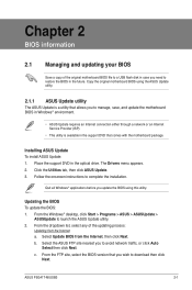
...future. Quit all Windows® applications before you wish to avoid network traffic, or click Auto Select then click Next. ASUS P5G41T-M/USB3 2-1 Place the support DVD in the support DVD that you update the BIOS using this utility. c. From the FTP ...original motherboard BIOS using the ASUS Update utility. 2.1.1 ASUS Update utility The ASUS Update is available in the optical drive. Installing ASUS Update To install ASUS Update: 1. Click the Utilities tab, then click ASUS Update. 3. Follow the onscreen instructions to launch the ASUS Update utility. 2. Updating the...
...future. Quit all Windows® applications before you wish to avoid network traffic, or click Auto Select then click Next. ASUS P5G41T-M/USB3 2-1 Place the support DVD in the support DVD that you update the BIOS using this utility. c. From the FTP ...original motherboard BIOS using the ASUS Update utility. 2.1.1 ASUS Update utility The ASUS Update is available in the optical drive. Installing ASUS Update To install ASUS Update: 1. Click the Utilities tab, then click ASUS Update. 3. Follow the onscreen instructions to launch the ASUS Update utility. 2. Updating the...
User Manual
Page 41
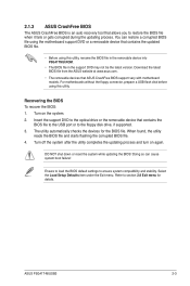
...Recovering the BIOS To recover the BIOS: 1. Turn off the system after the utility completes the updating process and turn on the system. 2. ASUS P5G41T-M/USB3 2-3 Turn on again. For motherboards without the floppy connector, prepare a USB flash disk before using this utility. Insert the support DVD to ... contains the BIOS file to the USB port or to ensure system compatibility and stability. Download the latest BIOS file from the ASUS website at www.asus.com. • The removable devices that contains the updated BIOS file. • Before using this utility, rename the BIOS...
...Recovering the BIOS To recover the BIOS: 1. Turn off the system after the utility completes the updating process and turn on the system. 2. ASUS P5G41T-M/USB3 2-3 Turn on again. For motherboards without the floppy connector, prepare a USB flash disk before using this utility. Insert the support DVD to ... contains the BIOS file to the USB port or to ensure system compatibility and stability. Download the latest BIOS file from the ASUS website at www.asus.com. • The removable devices that contains the updated BIOS file. • Before using this utility, rename the BIOS...
User Manual
Page 43
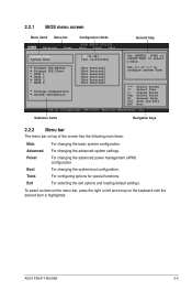
... Field F1 General Help F10 Save and Exit ESC Exit v02.61 (C)Copyright 1985-2010, American Megatrends, Inc. Boot For changing the system boot configuration. ASUS P5G41T-M/USB3 2-5 2.2.1 BIOS menu screen Menu items Menu bar Main Advanced Power Configuration fields BIOS SETUP UTILITY Boot Tools Exit General help System Time [00:31:48...
... Field F1 General Help F10 Save and Exit ESC Exit v02.61 (C)Copyright 1985-2010, American Megatrends, Inc. Boot For changing the system boot configuration. ASUS P5G41T-M/USB3 2-5 2.2.1 BIOS menu screen Menu items Menu bar Main Advanced Power Configuration fields BIOS SETUP UTILITY Boot Tools Exit General help System Time [00:31:48...
User Manual
Page 45
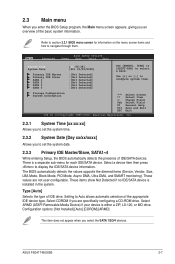
... IDE Master/Slave, SATA1~4 While entering Setup, the BIOS automatically detects the presence of IDE/SATA devices. These values are specifically configuring a CD-ROM drive. ASUS P5G41T-M/USB3 2-7 2.3 Main menu When you enter the BIOS Setup program, the Main menu screen appears, giving you to set the system time. 2.3.2 System Date [Day xx...
... IDE Master/Slave, SATA1~4 While entering Setup, the BIOS automatically detects the presence of IDE/SATA devices. These values are specifically configuring a CD-ROM drive. ASUS P5G41T-M/USB3 2-7 2.3 Main menu When you enter the BIOS Setup program, the Main menu screen appears, giving you to set the system time. 2.3.2 System Date [Day xx...
User Manual
Page 47
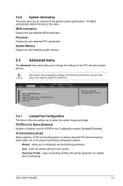
... devices. Configuration options: [Enabled] [Disabled] AI Overclocking [Auto] Allows selection of the preset overclocking configuration options: Manual - loads the optimal settings for stability when overclocking. ASUS P5G41T-M/USB3 2-9 Processor Displays the auto-detected CPU specification. Auto - loads overclocking profiles with optimal parameters for the system. 2.3.5 System Information This menu gives you to achieve...
... devices. Configuration options: [Enabled] [Disabled] AI Overclocking [Auto] Allows selection of the preset overclocking configuration options: Manual - loads the optimal settings for stability when overclocking. ASUS P5G41T-M/USB3 2-9 Processor Displays the auto-detected CPU specification. Auto - loads overclocking profiles with optimal parameters for the system. 2.3.5 System Information This menu gives you to achieve...

User Manual
Page 49
...] Sets the ration between CPU core clock and the FSB frequency. Key in CMOS then actual and set the VTT voltage. Configuration options: [Disabled] [Enabled] ASUS P5G41T-M/USB3 2-11 Configuration option: [Auto] • If an invalid ratio is set in the value directly or�u�s��e t�o��a��...
...] Sets the ration between CPU core clock and the FSB frequency. Key in CMOS then actual and set the VTT voltage. Configuration options: [Disabled] [Enabled] ASUS P5G41T-M/USB3 2-11 Configuration option: [Auto] • If an invalid ratio is set in the value directly or�u�s��e t�o��a��...


