User Manual
Page 3
......vi Safety information vii About this guide vii P5G41T-M LX3 specifications summary ix Chapter 1: Product introduction 1.1 Welcome 1-1 1.2 Package contents 1-1 1.3 Special features 1-1 1.3.1 Product highlights 1-1 1.3.2 Innovative ASUS features 1-2 1.4 Before you proceed 1-4 1.5 Motherboard overview 1-5 1.5.1 Placement direction 1-5 1.5.2 Screw holes 1-5 1.5.3 Motherboard layout 1-6 1.5.4 Layout contents 1-6 1.6 Central Processing Unit (CPU 1-7 1.6.1 Installing the CPU 1-7 1.6.2 Installing the CPU heatsink and fan 1-10 1.6.3 Uninstalling the...
......vi Safety information vii About this guide vii P5G41T-M LX3 specifications summary ix Chapter 1: Product introduction 1.1 Welcome 1-1 1.2 Package contents 1-1 1.3 Special features 1-1 1.3.1 Product highlights 1-1 1.3.2 Innovative ASUS features 1-2 1.4 Before you proceed 1-4 1.5 Motherboard overview 1-5 1.5.1 Placement direction 1-5 1.5.2 Screw holes 1-5 1.5.3 Motherboard layout 1-6 1.5.4 Layout contents 1-6 1.6 Central Processing Unit (CPU 1-7 1.6.1 Installing the CPU 1-7 1.6.2 Installing the CPU heatsink and fan 1-10 1.6.3 Uninstalling the...

User Manual
Page 4
Contents 1.11 Software support 1-25 1.11.1 Installing an operating system 1-25 1.11.2 Support DVD information 1-25 Chapter 2: BIOS information 2.1 Managing and updating your BIOS 2-1 2.1.1 ASUS Update utility 2-1 2.1.2 ASUS EZ Flash 2 2-2 2.1.3 ASUS CrashFree BIOS 2-3 2.2 BIOS setup program 2-4 2.2.1 BIOS menu screen 2-5 2.2.2 Menu bar 2-5 2.2.3 Navigation keys 2-6 2.2.4 Menu items 2-6 2.2.5 Submenu items 2-6 2.2.6 Configuration fields 2-6 2.2.7 Pop-up window 2-6 2.2.8 Scroll bar 2-6 2.2.9 General...
Contents 1.11 Software support 1-25 1.11.1 Installing an operating system 1-25 1.11.2 Support DVD information 1-25 Chapter 2: BIOS information 2.1 Managing and updating your BIOS 2-1 2.1.1 ASUS Update utility 2-1 2.1.2 ASUS EZ Flash 2 2-2 2.1.3 ASUS CrashFree BIOS 2-3 2.2 BIOS setup program 2-4 2.2.1 BIOS menu screen 2-5 2.2.2 Menu bar 2-5 2.2.3 Navigation keys 2-6 2.2.4 Menu items 2-6 2.2.5 Submenu items 2-6 2.2.6 Configuration fields 2-6 2.2.7 Pop-up window 2-6 2.2.8 Scroll bar 2-6 2.2.9 General...
User Manual
Page 6
... an outlet on a circuit different from digital apparatus set out in a particular installation. This equipment generates, uses and can be placed in our products at ASUS REACH website at http://csr.asus.com/english/REACH.htm. This equipment has been tested and found to comply with...waste. Check local regulations for radio noise emissions from that to which can radiate radio frequency energy and, if not installed and used in a residential installation. This symbol of Chemicals) regulatory framework, we published the chemical substances in municipal waste. This symbol of the ...
... an outlet on a circuit different from digital apparatus set out in a particular installation. This equipment generates, uses and can be placed in our products at ASUS REACH website at http://csr.asus.com/english/REACH.htm. This equipment has been tested and found to comply with...waste. Check local regulations for radio noise emissions from that to which can radiate radio frequency energy and, if not installed and used in a residential installation. This symbol of Chemicals) regulatory framework, we published the chemical substances in municipal waste. This symbol of the ...
User Manual
Page 7
...contains the following parts: • Chapter 1: Product introduction This chapter describes the features of the electrical outlet you need when installing and configuring the motherboard. Detailed descriptions of the BIOS parameters are unplugged before you detect any area where it may become wet...the system, ensure that all power cables from the existing system before the signal cables are not damaged. Operation safety • Before installing the motherboard and adding devices on a stable surface. • If you encounter technical problems with the package. • Before ...
...contains the following parts: • Chapter 1: Product introduction This chapter describes the features of the electrical outlet you need when installing and configuring the motherboard. Detailed descriptions of the BIOS parameters are unplugged before you detect any area where it may become wet...the system, ensure that all power cables from the existing system before the signal cables are not damaged. Operation safety • Before installing the motherboard and adding devices on a stable surface. • If you encounter technical problems with the package. • Before ...
User Manual
Page 9
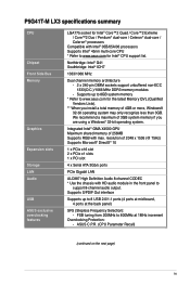
...® 05B/05A/06 processors Supports Intel® 45nm multi-core CPU * Refer to www.asus.com for Intel® CPU support list. We recommend a maximum of 3GB system memory if you install a total memory of 2048 x 1536 (@ 75Hz) Supports Microsoft® DirectX® 10 1...2 x 240-pin DIMM sockets support unbuffered non-ECC 1333(O.C.)/1066 MHz DDR3 memory modules - P5G41T-M LX3 specifications summary CPU Chipset Front Side Bus Memory Graphics Expansion slots Storage LAN Audio USB ASUS exclusive overclocking features LGA775 socket for Intel® Core™2 Quad / Core™2 Extreme ...
...® 05B/05A/06 processors Supports Intel® 45nm multi-core CPU * Refer to www.asus.com for Intel® CPU support list. We recommend a maximum of 3GB system memory if you install a total memory of 2048 x 1536 (@ 75Hz) Supports Microsoft® DirectX® 10 1...2 x 240-pin DIMM sockets support unbuffered non-ECC 1333(O.C.)/1066 MHz DDR3 memory modules - P5G41T-M LX3 specifications summary CPU Chipset Front Side Bus Memory Graphics Expansion slots Storage LAN Audio USB ASUS exclusive overclocking features LGA775 socket for Intel® Core™2 Quad / Core™2 Extreme ...
User Manual
Page 11
... FSB. Thank you start installing the motherboard, and hardware devices on it another standout in the 45nm manufacturing process. Before you for multitasking, multimedia, and enthusiastic gamers with the list below. 1.2 Package contents Check your motherboard package for the following items. Motherboard Cables Accessories Application DVD Documentation ASUS P5G41T-M LX3 motherboard 2 x Serial ATA 3.0Gb...
... FSB. Thank you start installing the motherboard, and hardware devices on it another standout in the 45nm manufacturing process. Before you for multitasking, multimedia, and enthusiastic gamers with the list below. 1.2 Package contents Check your motherboard package for the following items. Motherboard Cables Accessories Application DVD Documentation ASUS P5G41T-M LX3 motherboard 2 x Serial ATA 3.0Gb...
User Manual
Page 14
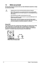
... or change any motherboard settings. • Unplug the power cord from the power supply. Onboard LED The motherboard comes with the component. • Before you install or remove any component, ensure that the ATX power supply is switched off mode. Failure to do so may cause severe damage to indicate that... you uninstall any component, place it on a grounded antistatic pad or in any motherboard component. 1.4 Before you proceed Take note of the onboard LED. SB_PWR P5G41T-M LX3 ON OFF Standby Power Powered Off P5G41T-M LX3 Onboard LED 1-4 Chapter 1: Product introduction
... or change any motherboard settings. • Unplug the power cord from the power supply. Onboard LED The motherboard comes with the component. • Before you install or remove any component, ensure that the ATX power supply is switched off mode. Failure to do so may cause severe damage to indicate that... you uninstall any component, place it on a grounded antistatic pad or in any motherboard component. 1.4 Before you proceed Take note of the onboard LED. SB_PWR P5G41T-M LX3 ON OFF Standby Power Powered Off P5G41T-M LX3 Onboard LED 1-4 Chapter 1: Product introduction
User Manual
Page 15
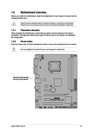
...the image below. 1.5.2 Screw holes Place six screws into the chassis in the correct orientation. 1.5 Motherboard overview Before you install the motherboard, study the configuration of your chassis to ensure that the motherboard fits into it into the holes indicated by... power cord before installing or removing the motherboard. Doing so can cause you physical injury and damage motherboard components. 1.5.1 Placement direction When installing the motherboard, ensure that you place it . Place this side towards the rear of the chassis P5G41T-M LX3 ASUS P5G41T-M LX3 1-5 Failure to do...
...the image below. 1.5.2 Screw holes Place six screws into the chassis in the correct orientation. 1.5 Motherboard overview Before you install the motherboard, study the configuration of your chassis to ensure that the motherboard fits into it into the holes indicated by... power cord before installing or removing the motherboard. Doing so can cause you physical injury and damage motherboard components. 1.5.1 Placement direction When installing the motherboard, ensure that you place it . Place this side towards the rear of the chassis P5G41T-M LX3 ASUS P5G41T-M LX3 1-5 Failure to do...
User Manual
Page 17
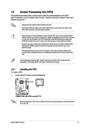
...ASUS will shoulder the cost of repair only if the damage is shipment/transit-related. • Keep the cap after installing the motherboard. The motherboard supports Intel® LGA775 processors with the Intel® Enhanced Intel SpeedStep® Technology (EIST) and Hyper-Threading Technology. 1.6.1 Installing the CPU To install a CPU: 1. Contact your left. P5G41T-M LX3 P5G41T-M LX3... CPU socket 775 Before installing the CPU, ensure that the PnP cap...
...ASUS will shoulder the cost of repair only if the damage is shipment/transit-related. • Keep the cap after installing the motherboard. The motherboard supports Intel® LGA775 processors with the Intel® Enhanced Intel SpeedStep® Technology (EIST) and Hyper-Threading Technology. 1.6.1 Installing the CPU To install a CPU: 1. Contact your left. P5G41T-M LX3 P5G41T-M LX3... CPU socket 775 Before installing the CPU, ensure that the PnP cap...
User Manual
Page 18
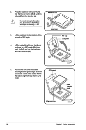
... with your thumb and forefinger to the left corner of the arrow to the socket pins, do not remove the PnP cap unless you are installing a CPU. 3. To prevent damage to a 135º angle. 4. Retention tab A B Load lever PnP cap Load plate 4B 4A 3 5. Lift the load lever in the direction...
... with your thumb and forefinger to the left corner of the arrow to the socket pins, do not remove the PnP cap unless you are installing a CPU. 3. To prevent damage to a 135º angle. 4. Retention tab A B Load lever PnP cap Load plate 4B 4A 3 5. Lift the load lever in the direction...
User Manual
Page 20
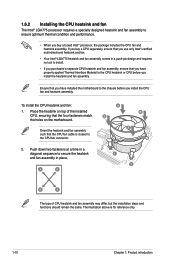
...10 Chapter 1: Product introduction Place the heatsink on top of CPU heatsink and fan assembly may differ, but the installation steps and functions should remain the same. To install the CPU heatsink and fan: 1. Push down two fasteners at a time in a diagonal sequence to secure ... is closest to the CPU fan connector. 2. A B A B B A 1 1 B A The type of the installed CPU, ensuring that the four fasteners match the holes on the motherboard. 1.6.2 Installing the CPU heatsink and fan The Intel® LGA775 processor requires a specially designed heatsink and fan assembly to ensure...
...10 Chapter 1: Product introduction Place the heatsink on top of CPU heatsink and fan assembly may differ, but the installation steps and functions should remain the same. To install the CPU heatsink and fan: 1. Push down two fasteners at a time in a diagonal sequence to secure ... is closest to the CPU fan connector. 2. A B A B B A 1 1 B A The type of the installed CPU, ensuring that the four fasteners match the holes on the motherboard. 1.6.2 Installing the CPU heatsink and fan The Intel® LGA775 processor requires a specially designed heatsink and fan assembly to ensure...
User Manual
Page 23
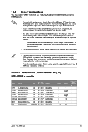
... vendor-marked value. • For system stability, use of memory, we recommend that you obtain memory modules from a memory module. Install a 64-bit Windows® OS when you are using a 32-bit Windows® OS. - For effective use a more memory...; • • • • • • • • • • • • • • • • • • ASUS P5G41T-M LX3 1-13 Any excess memory from the higher-sized channel is the standard way of accessing information from the same vendor. • Due to support a full...
... vendor-marked value. • For system stability, use of memory, we recommend that you obtain memory modules from a memory module. Install a 64-bit Windows® OS when you are using a 32-bit Windows® OS. - For effective use a more memory...; • • • • • • • • • • • • • • • • • • ASUS P5G41T-M LX3 1-13 Any excess memory from the higher-sized channel is the standard way of accessing information from the same vendor. • Due to support a full...
User Manual
Page 25
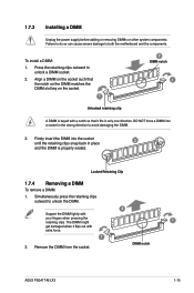
... 2. DO NOT force a DIMM into the socket until the retaining clips snap back in only one direction. Locked Retaining Clip 1.7.4 Removing a DIMM To remove a DIMM: 1. 1.7.3 Installing a DIMM Unplug the power supply before adding or removing DIMMs or other system components. Press the retaining clips outward to both the motherboard and the... to do so can cause severe damage to unlock a DIMM socket. 2. Simultaneously press the retaining clips outward to avoid damaging the DIMM. 3. DIMM notch ASUS P5G41T-M LX3 1-15 To install a DIMM: 1. Remove the DIMM from the socket.
... 2. DO NOT force a DIMM into the socket until the retaining clips snap back in only one direction. Locked Retaining Clip 1.7.4 Removing a DIMM To remove a DIMM: 1. 1.7.3 Installing a DIMM Unplug the power supply before adding or removing DIMMs or other system components. Press the retaining clips outward to both the motherboard and the... to do so can cause severe damage to unlock a DIMM socket. 2. Simultaneously press the retaining clips outward to avoid damaging the DIMM. 3. DIMM notch ASUS P5G41T-M LX3 1-15 To install a DIMM: 1. Remove the DIMM from the socket.
User Manual
Page 26
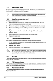
... slot This motherboard supports a PCI Express x16 graphics card that came with the slot and press firmly until the card is already installed in a chassis). 3. Align the card connector with it by adjusting the software settings. 1. 1.8 Expansion slots In the future,... you may cause you physical injury and damage motherboard components. 1.8.1 Installing an expansion card To install an expansion card: 1. Before installing the expansion card, read the documentation that complies with the screw you removed earlier. 6. Replace the system cover...
... slot This motherboard supports a PCI Express x16 graphics card that came with the slot and press firmly until the card is already installed in a chassis). 3. Align the card connector with it by adjusting the software settings. 1. 1.8 Expansion slots In the future,... you may cause you physical injury and damage motherboard components. 1.8.1 Installing an expansion card To install an expansion card: 1. Before installing the expansion card, read the documentation that complies with the screw you removed earlier. 6. Replace the system cover...
User Manual
Page 31
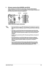
...system with a minimum of 400W. ATX power connectors (24-pin EATXPWR, 4-pin ATX12V) These connectors are designed to install additional devices. com/PowerSupplyCalculator/PSCalculator.aspx?SLanguage=en-us for ATX power supply plugs. Otherwise, the system will not ... power rating. The power supply plugs are for details. ATX12V EATXPWR +12V DC +12V DC P5G41T-M LX3 GND GND +3 Volts +12 Volts +12 Volts +5V Standby Power OK PIN 1 GND +5 Volts GND +5 Volts GND +3 ... ensure that the 20-pin power plug can provide at http://support.asus. ASUS P5G41T-M LX3 1-21 2.
...system with a minimum of 400W. ATX power connectors (24-pin EATXPWR, 4-pin ATX12V) These connectors are designed to install additional devices. com/PowerSupplyCalculator/PSCalculator.aspx?SLanguage=en-us for ATX power supply plugs. Otherwise, the system will not ... power rating. The power supply plugs are for details. ATX12V EATXPWR +12V DC +12V DC P5G41T-M LX3 GND GND +3 Volts +12 Volts +12 Volts +5V Standby Power OK PIN 1 GND +5 Volts GND +5 Volts GND +3 ... ensure that the 20-pin power plug can provide at http://support.asus. ASUS P5G41T-M LX3 1-21 2.
User Manual
Page 32
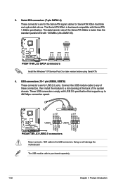
... GND RSATA_TXN1 RSATA_TXP1 GND GND RSATA_RXN2 RSATA_RXP2 GND RSATA_TXN2 RSATA_TXP2 GND GND RSATA_RXN3 RSATA_RXP3 GND RSATA_TXN3 RSATA_TXP3 GND P5G41T-M LX3 SATA1 SATA2 SATA3 P5G41T-M LX3 SATA connectors Install the Windows® XP Service Pack 3 or later version before using Serial ATA. 4. USB connectors...NC USB+5V USB_P7USB_P7+ GND USB+5V USB_P5USB_P5+ GND P5G41T-M LX3 USB56 PIN 1 USB78 PIN 1 P5G41T-M LX3 USB2.0 connectors Never connect a 1394 cable to a slot opening at the back of these connectors, then install the module to the USB connectors. These USB connectors...
... GND RSATA_TXN1 RSATA_TXP1 GND GND RSATA_RXN2 RSATA_RXP2 GND RSATA_TXN2 RSATA_TXP2 GND GND RSATA_RXN3 RSATA_RXP3 GND RSATA_TXN3 RSATA_TXP3 GND P5G41T-M LX3 SATA1 SATA2 SATA3 P5G41T-M LX3 SATA connectors Install the Windows® XP Service Pack 3 or later version before using Serial ATA. 4. USB connectors...NC USB+5V USB_P7USB_P7+ GND USB+5V USB_P5USB_P5+ GND P5G41T-M LX3 USB56 PIN 1 USB78 PIN 1 P5G41T-M LX3 USB2.0 connectors Never connect a 1394 cable to a slot opening at the back of these connectors, then install the module to the USB connectors. These USB connectors...
User Manual
Page 33
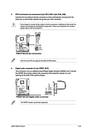
...on the fan connectors! CPU_FAN CPU FAN PWM CPU FAN IN CPU FAN PWR GND P5G41T-M LX3 CHA_FAN GND +12V Rotation P5G41T-M LX3 fan connectors Only the 4-pin CPU fan supports the ASUS Q-FAN feature. 6. Insufficient air flow inside the system may damage the motherboard components... chassis. +5V SPDIFOUT GND P5G41T-M LX3 SPDIF_OUT P5G41T-M LX3 Digital audio connector The S/PDIF module is for an additional Sony/Philips Digital Interface (S/PDIF) port. ASUS P5G41T-M LX3 1-23 These are not jumpers! Connect the S/PDIF Out module cable to this connector, then install the module to a slot...
...on the fan connectors! CPU_FAN CPU FAN PWM CPU FAN IN CPU FAN PWR GND P5G41T-M LX3 CHA_FAN GND +12V Rotation P5G41T-M LX3 fan connectors Only the 4-pin CPU fan supports the ASUS Q-FAN feature. 6. Insufficient air flow inside the system may damage the motherboard components... chassis. +5V SPDIFOUT GND P5G41T-M LX3 SPDIF_OUT P5G41T-M LX3 Digital audio connector The S/PDIF module is for an additional Sony/Philips Digital Interface (S/PDIF) port. ASUS P5G41T-M LX3 1-23 These are not jumpers! Connect the S/PDIF Out module cable to this connector, then install the module to a slot...
User Manual
Page 35
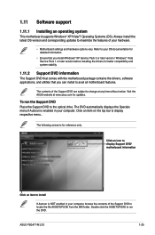
...support 1.11.1 Installing an operating system This motherboard supports Windows® XP/Vista/7 Operating Systems (OS). Visit the ASUS website at any time without notice. Click an item on the top bar to change at www.asus.com for reference only. To run the DVD. ASUS P5G41T-M LX3 1-25 The...Support DVD information The Support DVD that comes with the motherboard package contains the drivers, software applications, and utilities that you can install to avail all motherboard features. Double-click the ASSETUP.EXE to run the Support DVD Place the Support DVD to your computer. ...
...support 1.11.1 Installing an operating system This motherboard supports Windows® XP/Vista/7 Operating Systems (OS). Visit the ASUS website at any time without notice. Click an item on the top bar to change at www.asus.com for reference only. To run the DVD. ASUS P5G41T-M LX3 1-25 The...Support DVD information The Support DVD that comes with the motherboard package contains the drivers, software applications, and utilities that you can install to avail all motherboard features. Double-click the ASSETUP.EXE to run the Support DVD Place the Support DVD to your computer. ...
User Manual
Page 37
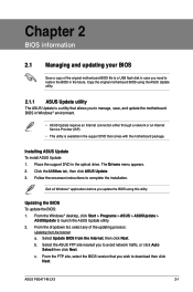
... utility. 2. The Drivers menu appears. 2. c. From the Windows® desktop, click Start > Programs > ASUS > ASUSUpdate > ASUSUpdate to download then click Next. ASUS P5G41T-M LX3 2-1 Select the ASUS FTP site nearest you to complete the installation. Place the support DVD in the optical drive. Follow the onscreen instructions to avoid network traffic, or click Auto Select then...
... utility. 2. The Drivers menu appears. 2. c. From the Windows® desktop, click Start > Programs > ASUS > ASUSUpdate > ASUSUpdate to download then click Next. ASUS P5G41T-M LX3 2-1 Select the ASUS FTP site nearest you to complete the installation. Place the support DVD in the optical drive. Follow the onscreen instructions to avoid network traffic, or click Auto Select then...
User Manual
Page 43
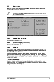
... the device was not previously formatted with LBA mode disabled. Storage Configuration System Information Select Screen Select Item +- Configuration options: [Disabled] [Auto] ASUS P5G41T-M LX3 2-7 Setting to select a field. There is installed in the system. Select a device item then press to navigate through them. These values are not user-configurable. 2.3 Main menu When you...
... the device was not previously formatted with LBA mode disabled. Storage Configuration System Information Select Screen Select Item +- Configuration options: [Disabled] [Auto] ASUS P5G41T-M LX3 2-7 Setting to select a field. There is installed in the system. Select a device item then press to navigate through them. These values are not user-configurable. 2.3 Main menu When you...


