User Manual
Page 3
Contents Notices...v Safety information vi Safety information vii P5G41-M SI specifications summary viii Chapter 1: Product introduction 1.1 Before you proceed 1-1 1.2 Motherboard overview 1-2 1.2.1 Motherboard layout 1-2 1.2.2 Layout contents 1-2 1.3 Central Processing Unit (CPU 1-3 1.4...1.8.1 Installing an operating system 1-17 1.8.2 Support DVD information 1-17 Chapter 2: BIOS information 2.1 Managing and updating your BIOS 2-1 2.1.1 ASUS Update utility 2-1 2.1.2 ASUS EZ Flash 2 utility 2-2 2.1.3 ASUS CrashFree BIOS 2-3 2.2 BIOS setup program 2-4 2.2.1 BIOS menu screen 2-5 iii
Contents Notices...v Safety information vi Safety information vii P5G41-M SI specifications summary viii Chapter 1: Product introduction 1.1 Before you proceed 1-1 1.2 Motherboard overview 1-2 1.2.1 Motherboard layout 1-2 1.2.2 Layout contents 1-2 1.3 Central Processing Unit (CPU 1-3 1.4...1.8.1 Installing an operating system 1-17 1.8.2 Support DVD information 1-17 Chapter 2: BIOS information 2.1 Managing and updating your BIOS 2-1 2.1.1 ASUS Update utility 2-1 2.1.2 ASUS EZ Flash 2 utility 2-2 2.1.3 ASUS CrashFree BIOS 2-3 2.2 BIOS setup program 2-4 2.2.1 BIOS menu screen 2-5 iii
User Manual
Page 8
... memory of 4GB capacity or more, Windows® 32-bit operating system may only recognize less than 3GB. P5G41-M SI specifications summary CPU Chipset System bus Memory Expansion slots VGA Storage LAN Audio USB ASUS Special features LGA775 Socket for Intel® C��o�re�™�2��E��...
... memory of 4GB capacity or more, Windows® 32-bit operating system may only recognize less than 3GB. P5G41-M SI specifications summary CPU Chipset System bus Memory Expansion slots VGA Storage LAN Audio USB ASUS Special features LGA775 Socket for Intel® C��o�re�™�2��E��...
User Manual
Page 10
... The illustration below shows the location of accessories. Before you for the list of the onboard LED. SB_PWR P5G41-M SI ON OFF Standby Power Powered Off P5G41-M SI Onboard LED 1-1 Chapter 1: Product introduction This is damaged or missing, contact your motherboard package. Failure to do... with a standby power LED that lights up to the motherboard, peripherals, or components. Refer to page ix for buying an ASUS® P5G41-M SI motherboard! Chapter 1 Product introduction Thank you start installing the motherboard, and hardware devices on it, check the items in your ...
... The illustration below shows the location of accessories. Before you for the list of the onboard LED. SB_PWR P5G41-M SI ON OFF Standby Power Powered Off P5G41-M SI Onboard LED 1-1 Chapter 1: Product introduction This is damaged or missing, contact your motherboard package. Failure to do... with a standby power LED that lights up to the motherboard, peripherals, or components. Refer to page ix for buying an ASUS® P5G41-M SI motherboard! Chapter 1 Product introduction Thank you start installing the motherboard, and hardware devices on it, check the items in your ...

User Manual
Page 11
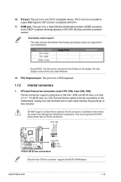
... this side towards the rear of the chassis. CHA_FAN LGA775 USB34 USBPW1-4 LAN1_USB12 RTL 8112L COM1 AUDIO ICS 9LRS954 PCIEX16 Intel® G41 Super I/O PCI1 P5G41-M SI PCI2 VIA VT1708S CD AAFP SPDIF_OUT PCI3 FLOPPY LPT Lithium Cell CMOS Power Intel® ICH7 SATA4 SATA3 SATA2 SATA1 USB56 USBPW5-8 USB78 8Mb F_PANEL...) 1-12 1-12 15. LPT connector (26-1 pin LTP) 1-16 1-3 16. Digital audio connector (4-1 pin SPDIF_OUT) 1-15 1-14 18. System panel connector (10-1 pin F_PANEL) 1-14 ASUS P5G41-M SI 1-2
... this side towards the rear of the chassis. CHA_FAN LGA775 USB34 USBPW1-4 LAN1_USB12 RTL 8112L COM1 AUDIO ICS 9LRS954 PCIEX16 Intel® G41 Super I/O PCI1 P5G41-M SI PCI2 VIA VT1708S CD AAFP SPDIF_OUT PCI3 FLOPPY LPT Lithium Cell CMOS Power Intel® ICH7 SATA4 SATA3 SATA2 SATA1 USB56 USBPW5-8 USB78 8Mb F_PANEL...) 1-12 1-12 15. LPT connector (26-1 pin LTP) 1-16 1-3 16. Digital audio connector (4-1 pin SPDIF_OUT) 1-15 1-14 18. System panel connector (10-1 pin F_PANEL) 1-14 ASUS P5G41-M SI 1-2

User Manual
Page 13
... address limitation on the 32-bit Windows® OS, when you do either of 3GB system memory if you can be about 3GB or less. ASUS P5G41-M SI 1-4 Install a maximum of the following: - Under the default state, some memory modules for the OS can : - install two identical DIMMs in all four slots; install...
... address limitation on the 32-bit Windows® OS, when you do either of 3GB system memory if you can be about 3GB or less. ASUS P5G41-M SI 1-4 Install a maximum of the following: - Under the default state, some memory modules for the OS can : - install two identical DIMMs in all four slots; install...
User Manual
Page 15
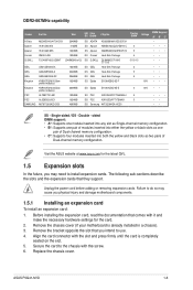
Remove the chassis cover (if your motherboard is completely seated on the slot. 5. Visit the ASUS website at www.asus.com for the card. 2. Before installing the expansion card, read the documentation that comes with the screw. 6.... 4 5-5-5-15 3 5 5 5 5 5 Voltage 1.8V 1.8V DIMM Support A* B* C •• SS - Double - Remove the bracket opposite the slot that they support. ASUS P5G41-M SI 1-6 Unplug the power cord before adding or removing expansion cards. Replace the chassis cover. The following sub-sections describe the slots and the expansion cards...
Remove the chassis cover (if your motherboard is completely seated on the slot. 5. Visit the ASUS website at www.asus.com for the card. 2. Before installing the expansion card, read the documentation that comes with the screw. 6.... 4 5-5-5-15 3 5 5 5 5 5 Voltage 1.8V 1.8V DIMM Support A* B* C •• SS - Double - Remove the bracket opposite the slot that they support. ASUS P5G41-M SI 1-6 Unplug the power cord before adding or removing expansion cards. Replace the chassis cover. The following sub-sections describe the slots and the expansion cards...

User Manual
Page 17
...to overclocking, use the CPU Parameter Recall (C.P.R.) feature. USBPW1-4 12 23 +5V +5VSB (Default) USBPW5-8 P5G41-M SI 12 23 +5V +5VSB (Default) P5G41-M SI USB Device Wake Up • The USB device wake-up . • The total current consumed must NOT... supply capability (+5VSB) whether under normal condition or in the BIOS. KBPWR 12 23 +5V +5VSB (Default) P5G41-M SI P5G41-M SI Keyboard Power Setting 3. • If the steps above do not need to clear the RTC when the system hangs... least 1A on the +5VSB lead, and a corresponding setting in sleep mode. ASUS P5G41-M SI 1-8
...to overclocking, use the CPU Parameter Recall (C.P.R.) feature. USBPW1-4 12 23 +5V +5VSB (Default) USBPW5-8 P5G41-M SI 12 23 +5V +5VSB (Default) P5G41-M SI USB Device Wake Up • The USB device wake-up . • The total current consumed must NOT... supply capability (+5VSB) whether under normal condition or in the BIOS. KBPWR 12 23 +5V +5VSB (Default) P5G41-M SI P5G41-M SI Keyboard Power Setting 3. • If the steps above do not need to clear the RTC when the system hangs... least 1A on the +5VSB lead, and a corresponding setting in sleep mode. ASUS P5G41-M SI 1-8
User Manual
Page 19
... (24 W max.) or a total of the connector. CPU_FAN GND CPU FAN PWR CPU FAN IN CPU FAN PWM P5G41-M SI CHA_FAN GND +12V Rotation P5G41-M SI fan connectors Only the 4-pin CPU fan connector supports the ASUS Q-FAN feature. Insufficient air flow inside the system may damage the motherboard components. This port is for any...
... (24 W max.) or a total of the connector. CPU_FAN GND CPU FAN PWR CPU FAN IN CPU FAN PWM P5G41-M SI CHA_FAN GND +12V Rotation P5G41-M SI fan connectors Only the 4-pin CPU fan connector supports the ASUS Q-FAN feature. Insufficient air flow inside the system may damage the motherboard components. This port is for any...
User Manual
Page 21
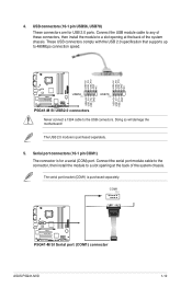
... (10-1 pin COM1) The connector is for USB 2.0 ports. COM1 PIN 1 P5G41-M SI P5G41-M SI Serial port (COM1) connector ASUS P5G41-M SI 1-12 USB+5V USB_P8USB_P8+ GND NC USB+5V USB_P6USB_P6+ GND NC P5G41-M SI USB56 PIN 1 USB78 PIN 1 USB+5V USB_P7USB_P7+ GND USB+5V USB_P5USB_P5+ GND P5G41-M SI USB2.0 connectors Never connect a 1394 cable to 480Mbps connection speed. Connect the...
... (10-1 pin COM1) The connector is for USB 2.0 ports. COM1 PIN 1 P5G41-M SI P5G41-M SI Serial port (COM1) connector ASUS P5G41-M SI 1-12 USB+5V USB_P8USB_P8+ GND NC USB+5V USB_P6USB_P6+ GND NC P5G41-M SI USB56 PIN 1 USB78 PIN 1 USB+5V USB_P7USB_P7+ GND USB+5V USB_P5USB_P5+ GND P5G41-M SI USB2.0 connectors Never connect a 1394 cable to 480Mbps connection speed. Connect the...
User Manual
Page 23
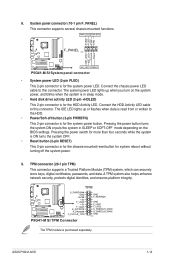
...) This connector supports a Trusted Platform Module (TPM) system, which can securely store keys, digital certificates, passwords, and data. ASUS P5G41-M SI 1-14 8. System panel connector (10-1 pin F_PANEL) This connector supports several chassis-mounted functions. Connect the chassis power LED cable... 1 IDE_LED+ IDE_LED- Connect the HDD Activity LED cable to this connector. TPM P5G41-M SI S_PWRDWN# GND +3VSB +3V F_LAD0 +3V F_LAD3 S_PLTRST# F_FRAME# C_PCICLK_TPM P5G41-M SI TPM Connector GND F_SERIRQ# GND F_LAD1 F_LAD2 S_SMBCLIK_MAIN S_SMBCLIK_MAIN GND PIN 1 The TPM module...
...) This connector supports a Trusted Platform Module (TPM) system, which can securely store keys, digital certificates, passwords, and data. ASUS P5G41-M SI 1-14 8. System panel connector (10-1 pin F_PANEL) This connector supports several chassis-mounted functions. Connect the chassis power LED cable... 1 IDE_LED+ IDE_LED- Connect the HDD Activity LED cable to this connector. TPM P5G41-M SI S_PWRDWN# GND +3VSB +3V F_LAD0 +3V F_LAD3 S_PLTRST# F_FRAME# C_PCICLK_TPM P5G41-M SI TPM Connector GND F_SERIRQ# GND F_LAD1 F_LAD2 S_SMBCLIK_MAIN S_SMBCLIK_MAIN GND PIN 1 The TPM module...
User Manual
Page 25
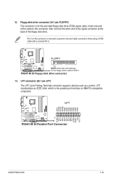
FLOPPY P5G41-M SI PIN1 NOTE:Orient the red markings on the floppy ribbon cable to prevent incorrect cable connection when using a FDD cable with a covered Pin 5. LPT standardizes ...# SLIN# GND GND GND GND GND GND GND GND PIN 1 STB# PD0 PD1 PD2 PD3 PD4 PD5 PD6 PD7 ACK# BUSY PE SLCT P5G41-M SI P5G41-M SI Parallel Port Connector ASUS P5G41-M SI 1-16 P5G41-M SI Floppy disk drive connector 13. Floppy disk drive connector (34-1 pin FLOPPY) This connector is the parallel port interface on the connector is...
FLOPPY P5G41-M SI PIN1 NOTE:Orient the red markings on the floppy ribbon cable to prevent incorrect cable connection when using a FDD cable with a covered Pin 5. LPT standardizes ...# SLIN# GND GND GND GND GND GND GND GND PIN 1 STB# PD0 PD1 PD2 PD3 PD4 PD5 PD6 PD7 ACK# BUSY PE SLCT P5G41-M SI P5G41-M SI Parallel Port Connector ASUS P5G41-M SI 1-16 P5G41-M SI Floppy disk drive connector 13. Floppy disk drive connector (34-1 pin FLOPPY) This connector is the parallel port interface on the connector is...

User Manual
Page 27
... Windows® environment. This utility is a utility that comes with the motherboard package. Follow the onscreen instructions to launch the ASUS Update utility. 2. ASUS P5G41-M SI 2-1 From the Windows® desktop, click Start > Programs > ASUS > ASUSUpdate > ASUSUpdate to complete the updating process. Chapter 2 BIOS information 2.1 Managing and updating your BIOS Save a copy of the original...
... Windows® environment. This utility is a utility that comes with the motherboard package. Follow the onscreen instructions to launch the ASUS Update utility. 2. ASUS P5G41-M SI 2-1 From the Windows® desktop, click Start > Programs > ASUS > ASUSUpdate > ASUSUpdate to complete the updating process. Chapter 2 BIOS information 2.1 Managing and updating your BIOS Save a copy of the original...
User Manual
Page 29
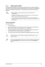
... file when it fails or gets corrupted during the updating process. Download the latest BIOS file from the ASUS website at www.asus.com. • The removable device that ASUS CrashFree BIOS support vary with motherboard models. Recovering the BIOS To recover the BIOS: 1. When found,...For motherboards without the floppy connector, prepare a USB flash disk before using this utility. The utility automatically checks the devices for details. ASUS P5G41-M SI 2-3 Insert the support DVD to the optical drive or the removable device that contains the BIOS file to the USB port or to ...
... file when it fails or gets corrupted during the updating process. Download the latest BIOS file from the ASUS website at www.asus.com. • The removable device that ASUS CrashFree BIOS support vary with motherboard models. Recovering the BIOS To recover the BIOS: 1. When found,...For motherboards without the floppy connector, prepare a USB flash disk before using this utility. The utility automatically checks the devices for details. ASUS P5G41-M SI 2-3 Insert the support DVD to the optical drive or the removable device that contains the BIOS file to the USB port or to ...

User Manual
Page 31
..., selecting Main shows the Main menu items. The other items (Advanced, Power, Boot, Tools, and Exit) on the menu bar have their respective menu items. ASUS P5G41-M SI 2-5 2.2.1 BIOS menu screen Menu items Menu bar Main Advanced Power Configuration fields BIOS SETUP UTILITY Boot Tools Exit General help System Time [00:31:48...
..., selecting Main shows the Main menu items. The other items (Advanced, Power, Boot, Tools, and Exit) on the menu bar have their respective menu items. ASUS P5G41-M SI 2-5 2.2.1 BIOS menu screen Menu items Menu bar Main Advanced Power Configuration fields BIOS SETUP UTILITY Boot Tools Exit General help System Time [00:31:48...
User Manual
Page 33
... appropriate IDE device type. Setting to the device occurs one sector at a time if the device supports multi-sector transfer feature. Configuration options: [Disabled] [Enabled] ASUS P5G41-M SI 2-7 2.3.1 System Time [xx:xx:xx] Allows you to set the system time. 2.3.2 System Date [Day xx/xx/xxxx] Allows you to display the IDE/SATA...
... appropriate IDE device type. Setting to the device occurs one sector at a time if the device supports multi-sector transfer feature. Configuration options: [Disabled] [Enabled] ASUS P5G41-M SI 2-7 2.3.1 System Time [xx:xx:xx] Allows you to set the system time. 2.3.2 System Date [Day xx/xx/xxxx] Allows you to display the IDE/SATA...
User Manual
Page 35
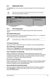
... options: [Disabled] [Enabled] Max CPUID Value Limit [Disabled] Setting this menu show the CPU-related information that the BIOS automatically detects. Configuration options: [Disabled] [Enabled] ASUS P5G41-M SI 2-9 Main Advanced Power BIOS SETUP UTILITY Boot Tools Exit CPU Configuration Chipset Onboard Devices Configuration USB Configuration PCIPnP Adjust System frequency/voltage. 2.4.1 CPU Configuration The...
... options: [Disabled] [Enabled] Max CPUID Value Limit [Disabled] Setting this menu show the CPU-related information that the BIOS automatically detects. Configuration options: [Disabled] [Enabled] ASUS P5G41-M SI 2-9 Main Advanced Power BIOS SETUP UTILITY Boot Tools Exit CPU Configuration Chipset Onboard Devices Configuration USB Configuration PCIPnP Adjust System frequency/voltage. 2.4.1 CPU Configuration The...

User Manual
Page 37
... disable the onboard LAN controller. Configuration options: [Normal] [IrDA] [ASK IR] 2.4.4 USB Configuration The items in the onboard LAN controller. Configuration options: [Disabled] [Enabled] [Auto] ASUS P5G41-M SI 2-11 Configuration options: [Enabled] [Disabled] Onboard LAN Boot ROM [Disabled] Allows you to enable or disable support for Legacy USB storage devices, including USB flash...
... disable the onboard LAN controller. Configuration options: [Normal] [IrDA] [ASK IR] 2.4.4 USB Configuration The items in the onboard LAN controller. Configuration options: [Disabled] [Enabled] [Auto] ASUS P5G41-M SI 2-11 Configuration options: [Enabled] [Disabled] Onboard LAN Boot ROM [Disabled] Allows you to enable or disable support for Legacy USB storage devices, including USB flash...

User Manual
Page 39
... or event, the system resumes to enable or disable the Advanced Configuration and Power Interface (ACPI) support in a low power mode. Configuration options: [Disabled] [Enabled] ASUS P5G41-M SI 2-13 Configuration options: [S1 (POS) Only] [S3 Only] [Auto] [S1(POS) Only] - Enables the system to [Power Off], the system goes into either off or...
... or event, the system resumes to enable or disable the Advanced Configuration and Power Interface (ACPI) support in a low power mode. Configuration options: [Disabled] [Enabled] ASUS P5G41-M SI 2-13 Configuration options: [S1 (POS) Only] [S3 Only] [Auto] [S1(POS) Only] - Enables the system to [Power Off], the system goes into either off or...

User Manual
Page 41
...options: [Removable Dev.] [Hard Drive] [ATAPI CD-ROM] [Disabled] • To select the boot device suring system startup, press when ASUS Logo appears. • To access Windows® OS in the system. A virtual drive (Drive B:) may appear when you set to [...system boot options. AddOn ROM Display Mode [Force BIOS] Sets the display mode for the NumLock. Configuration options: [Off] [On] ASUS P5G41-M SI 2-15 Main Advanced Power BIOS SETUP UTILITY Boot Tools Exit Boot Settings Boot Device Priority Boot Settings Configuration Security Specifies the Boot Device Priority ...
...options: [Removable Dev.] [Hard Drive] [ATAPI CD-ROM] [Disabled] • To select the boot device suring system startup, press when ASUS Logo appears. • To access Windows® OS in the system. A virtual drive (Drive B:) may appear when you set to [...system boot options. AddOn ROM Display Mode [Force BIOS] Sets the display mode for the NumLock. Configuration options: [Off] [On] ASUS P5G41-M SI 2-15 Main Advanced Power BIOS SETUP UTILITY Boot Tools Exit Boot Settings Boot Device Priority Boot Settings Configuration Security Specifies the Boot Device Priority ...
User Manual
Page 43
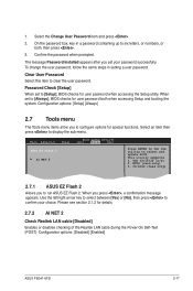
... 2. Use the left/right arrow key to select between [Yes] or [No], then press to confirm your password successfully. Configuration options: [Disabled] [Enabled] ASUS P5G41-M SI 2-17 To change the user password, follow the same steps in a password containing up to select and update BIOS. Configuration options: [Setup] [Always] 2.7 ...the Realtek LAN cable during the Power-On Self‑Test (POST). Main Advanced Power BIOS SETUP UTILITY Boot Tools Exit ASUS EZ Flash 2 AI NET 2 Press ENTER to [Always], BIOS checks for user password when accessing the Setup utility. NTFS (read only...
... 2. Use the left/right arrow key to select between [Yes] or [No], then press to confirm your password successfully. Configuration options: [Disabled] [Enabled] ASUS P5G41-M SI 2-17 To change the user password, follow the same steps in a password containing up to select and update BIOS. Configuration options: [Setup] [Always] 2.7 ...the Realtek LAN cable during the Power-On Self‑Test (POST). Main Advanced Power BIOS SETUP UTILITY Boot Tools Exit ASUS EZ Flash 2 AI NET 2 Press ENTER to [Always], BIOS checks for user password when accessing the Setup utility. NTFS (read only...


