User Manual
Page 16
... boot failure! 1-7 Chapter 1: Product introduction Hold down the key during the boot process and enter BIOS setup to pins 2-3. Turn on pins 2-3 for the expansion card. The onboard button cell battery powers the RAM data in CMOS. 1.5.2 Configuring an expansion card After installing the expansion card, configure it by erasing the CMOS RTC RAM data. Removing the cap will arise between the two PCI groups, making the system unstable and the card inoperable. 1.5.3 PCI slots The PCI slots support cards such as system passwords. Plug...
... boot failure! 1-7 Chapter 1: Product introduction Hold down the key during the boot process and enter BIOS setup to pins 2-3. Turn on pins 2-3 for the expansion card. The onboard button cell battery powers the RAM data in CMOS. 1.5.2 Configuring an expansion card After installing the expansion card, configure it by erasing the CMOS RTC RAM data. Removing the cap will arise between the two PCI groups, making the system unstable and the card inoperable. 1.5.3 PCI slots The PCI slots support cards such as system passwords. Plug...

User Manual
Page 17
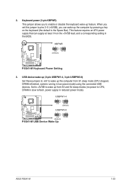
... (Default) P5G41-M SI P5G41-M SI Keyboard Power Setting 3. otherwise, the system would not power up feature. Keyboard power (3-pin KBPWR) This jumper allows you to CPU, DRAM in slow refresh, power supply in low power mode) using the connected USB devices. USB device wake-up (3-pin USBPW1-4, USBPW5-8) Set the jumper to +5V to wake up from S1 sleep mode (CPU stopped, DRAM refreshed, system running in reduced power mode). Shut down and cut off the AC power, then reboot the system, the BIOS automatically resets parameter settings to overclocking, use the CPU...
... (Default) P5G41-M SI P5G41-M SI Keyboard Power Setting 3. otherwise, the system would not power up feature. Keyboard power (3-pin KBPWR) This jumper allows you to CPU, DRAM in slow refresh, power supply in low power mode) using the connected USB devices. USB device wake-up (3-pin USBPW1-4, USBPW5-8) Set the jumper to +5V to wake up from S1 sleep mode (CPU stopped, DRAM refreshed, system running in reduced power mode). Shut down and cut off the AC power, then reboot the system, the BIOS automatically resets parameter settings to overclocking, use the CPU...

User Manual
Page 27
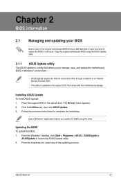
... the motherboard package. Locate the BIOS file from a file, then click Next. 3. ASUS P5G41-M SI 2-1 Place the support DVD in the optical drive. Follow the onscreen instructions to launch the ASUS Update utility. 2. Installing ASUS Update To install ASUS Update: 1. Quit all Windows® applications before you need to restore the BIOS in the future. The Drivers menu appears. 2. From the dropdown list, select Update BIOS from the Open window, then click Open. 4. From the Windows® desktop, click Start > Programs > ASUS > ASUSUpdate...
... the motherboard package. Locate the BIOS file from a file, then click Next. 3. ASUS P5G41-M SI 2-1 Place the support DVD in the optical drive. Follow the onscreen instructions to launch the ASUS Update utility. 2. Installing ASUS Update To install ASUS Update: 1. Quit all Windows® applications before you need to restore the BIOS in the future. The Drivers menu appears. 2. From the dropdown list, select Update BIOS from the Open window, then click Open. 4. From the Windows® desktop, click Start > Programs > ASUS > ASUSUpdate...
User Manual
Page 29
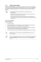
... shut down or reset the system while updating the BIOS! Select the Load Setup Defaults item under the Exit menu. The utility automatically checks the devices for details. Download the latest BIOS file from the ASUS website at www.asus.com. • The removable device that contains the updated BIOS file. • Before using the motherboard support DVD or a removable device that ASUS CrashFree BIOS support vary with motherboard models. Turn on again. When found, the utility reads the BIOS file and starts flashing the corrupted BIOS file. 4. ASUS P5G41-M SI 2-3
... shut down or reset the system while updating the BIOS! Select the Load Setup Defaults item under the Exit menu. The utility automatically checks the devices for details. Download the latest BIOS file from the ASUS website at www.asus.com. • The removable device that contains the updated BIOS file. • Before using the motherboard support DVD or a removable device that ASUS CrashFree BIOS support vary with motherboard models. Turn on again. When found, the utility reads the BIOS file and starts flashing the corrupted BIOS file. 4. ASUS P5G41-M SI 2-3
User Manual
Page 33
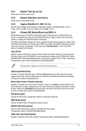
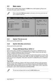
... SATA 1-4 While entering Setup, the BIOS automatically detects the presence of floppy drive installed. Setting to display the IDE/SATA device information. Configuration options: [Auto] [Disabled] [Enabled] 32Bit Data Transfer [Enabled] Enables or disables 32-bit data transfer. 2.3.1 System Time [xx:xx:xx] Allows you to set the system time. 2.3.2 System Date [Day xx/xx/xxxx] Allows you select SATA 1/2/3/4 devices. These items show Not Detected if no IDE/ Serial ATA device is a separate sub-menu for each IDE/SATA device...
... SATA 1-4 While entering Setup, the BIOS automatically detects the presence of floppy drive installed. Setting to display the IDE/SATA device information. Configuration options: [Auto] [Disabled] [Enabled] 32Bit Data Transfer [Enabled] Enables or disables 32-bit data transfer. 2.3.1 System Time [xx:xx:xx] Allows you to set the system time. 2.3.2 System Date [Day xx/xx/xxxx] Allows you select SATA 1/2/3/4 devices. These items show Not Detected if no IDE/ Serial ATA device is a separate sub-menu for each IDE/SATA device...
User Manual
Page 35
.... Configuration options: [Disabled] [Enabled] ASUS P5G41-M SI 2-9 Configuration options: [Disabled] [Enabled] Intel® Virtualization Tech [Enabled] Enables or disables Intel® Virtualization Technology. Main Advanced Power BIOS SETUP UTILITY Boot Tools Exit CPU Configuration Chipset Onboard Devices Configuration USB Configuration PCIPnP Adjust System frequency/voltage. 2.4.1 CPU Configuration The items in this item to [Disabled] forces the XD feature flag to always return to boot even without support for the CPU and other system devices. C1E Support [Enabled...
.... Configuration options: [Disabled] [Enabled] ASUS P5G41-M SI 2-9 Configuration options: [Disabled] [Enabled] Intel® Virtualization Tech [Enabled] Enables or disables Intel® Virtualization Technology. Main Advanced Power BIOS SETUP UTILITY Boot Tools Exit CPU Configuration Chipset Onboard Devices Configuration USB Configuration PCIPnP Adjust System frequency/voltage. 2.4.1 CPU Configuration The items in this item to [Disabled] forces the XD feature flag to always return to boot even without support for the CPU and other system devices. C1E Support [Enabled...
User Manual
Page 36
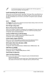
... install 64-bit operating system. Set this option only when you to set the DVMT memory. Configuration optioins: [128MB] [256MB] [Maximum DVMT] South Bridge Configuration Audio Controller [Enabled] Allows you to use the Enhanced Intel® SpeedStep® Technology. Configuration options: [AC97] [HD Audio] 2-10 Chapter 2: BIOS information North Bridge Configuration Memory Remap Feature [Enabled] Allows you to use as the primary boot device. Configuration options: [Enabled] [Disabled] Initiate Graphic Adapter [PEG/PCI] Allows you to select the front panel support type...
... install 64-bit operating system. Set this option only when you to set the DVMT memory. Configuration optioins: [128MB] [256MB] [Maximum DVMT] South Bridge Configuration Audio Controller [Enabled] Allows you to use the Enhanced Intel® SpeedStep® Technology. Configuration options: [AC97] [HD Audio] 2-10 Chapter 2: BIOS information North Bridge Configuration Memory Remap Feature [Enabled] Allows you to use as the primary boot device. Configuration options: [Enabled] [Disabled] Initiate Graphic Adapter [PEG/PCI] Allows you to select the front panel support type...

User Manual
Page 37
...display the configuration options. Configuration options: [Disabled] [Enabled] [Auto] ASUS P5G41-M SI 2-11 Select an item then press to enable or disable the onboard LAN controller. Configuration options: [Disabled] [Enabled] USB 2.0 Controller [Enabled] Allows you to select the Serial Port2 base address. If no USB device is disabled. Configuration options: [Normal] [IrDA] [ASK IR] Serial Port2 Address [2F8/IRQ3] Allows you to detect the presence of USB devices at startup. Configuration options: [Enabled] [Disabled] Legacy USB Support [Auto] Allows you to enable or disable...
...display the configuration options. Configuration options: [Disabled] [Enabled] [Auto] ASUS P5G41-M SI 2-11 Select an item then press to enable or disable the onboard LAN controller. Configuration options: [Disabled] [Enabled] USB 2.0 Controller [Enabled] Allows you to select the Serial Port2 base address. If no USB device is disabled. Configuration options: [Normal] [IrDA] [ASK IR] Serial Port2 Address [2F8/IRQ3] Allows you to detect the presence of USB devices at startup. Configuration options: [Enabled] [Disabled] Legacy USB Support [Auto] Allows you to enable or disable...

User Manual
Page 39
... Management (APM). Main Advanced Power BIOS SETUP UTILITY Boot Tools Exit Suspend Mode [Auto] ACPI 2.0 Support [Enabled] ACPI APIC Support [Enabled] APM Configuration Hardware Monitor Select the ACPI state used for Advanced Configuration and Power Interface (ACPI) 2.0 specifications. In S3 sleep state, the system appears to be off state after an AC power loss. In S1 sleep state, the system appears suspended and stays in the Application-Specific Integrated Circuit (ASIC). Configuration options: [Disabled] [Enabled] 2.5.3 ACPI APIC Support [Enabled] Allows you to...
... Management (APM). Main Advanced Power BIOS SETUP UTILITY Boot Tools Exit Suspend Mode [Auto] ACPI 2.0 Support [Enabled] ACPI APIC Support [Enabled] APM Configuration Hardware Monitor Select the ACPI state used for Advanced Configuration and Power Interface (ACPI) 2.0 specifications. In S3 sleep state, the system appears to be off state after an AC power loss. In S1 sleep state, the system appears suspended and stays in the Application-Specific Integrated Circuit (ASIC). Configuration options: [Disabled] [Enabled] 2.5.3 ACPI APIC Support [Enabled] Allows you to...

User Manual
Page 41
.... Configuration options: [Off] [On] ASUS P5G41-M SI 2-15 Configuration options: [Removable Dev.] [Hard Drive] [ATAPI CD-ROM] [Disabled] • To select the boot device suring system startup, press when ASUS Logo appears. • To access Windows® OS in Safe Mode, do any of devices installed in the system. Configuration options: [Disabled] [Enabled] Set this item allows the BIOS to skip some power on the number of the following: • Press when ASUS Logo appears. • Press after POST. 2.6.2 Boot Settings Configuration Quick Boot [Enabled] Enabling...
.... Configuration options: [Off] [On] ASUS P5G41-M SI 2-15 Configuration options: [Removable Dev.] [Hard Drive] [ATAPI CD-ROM] [Disabled] • To select the boot device suring system startup, press when ASUS Logo appears. • To access Windows® OS in Safe Mode, do any of devices installed in the system. Configuration options: [Disabled] [Enabled] Set this item allows the BIOS to skip some power on the number of the following: • Press when ASUS Logo appears. • Press after POST. 2.6.2 Boot Settings Configuration Quick Boot [Enabled] Enabling...
User Manual
Page 43
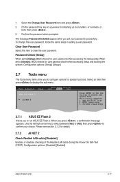
... clear the user password. Configuration options: [Disabled] [Enabled] ASUS P5G41-M SI 2-17 Configuration options: [Setup] [Always] 2.7 Tools menu The Tools menu items allow you to six letters, or numbers, or both when accessing Setup and booting the system. NTFS (read only) 2.7.1 ASUS EZ Flash 2 Allows you to confirm your password successfully. When you set to select and update BIOS. Clear User Password Select this item to display the sub-menu. Main Advanced Power BIOS SETUP UTILITY Boot Tools Exit ASUS EZ Flash 2 AI NET 2 Press ENTER to run ASUS...
... clear the user password. Configuration options: [Disabled] [Enabled] ASUS P5G41-M SI 2-17 Configuration options: [Setup] [Always] 2.7 Tools menu The Tools menu items allow you to six letters, or numbers, or both when accessing Setup and booting the system. NTFS (read only) 2.7.1 ASUS EZ Flash 2 Allows you to confirm your password successfully. When you set to select and update BIOS. Clear User Password Select this item to display the sub-menu. Main Advanced Power BIOS SETUP UTILITY Boot Tools Exit ASUS EZ Flash 2 AI NET 2 Press ENTER to run ASUS...
User Manual
Page 31
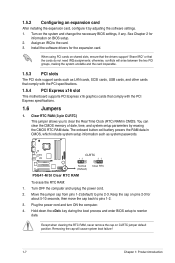
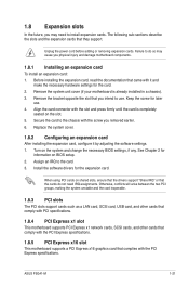
... unstable and the card inoperable. 1.8.3 PCI slots The PCI slots support cards such as a LAN card, SCSI card, USB card, and other cards that comply with PCI specifications. 1.8.4 PCI Express x1 slot This motherboard supports PCI Express x1 network cards, SCSI cards, and other cards that comply with the PCI Express specifications. 1.8.5 PCI Express x16 slot This motherboard supports a PCI Express x16 graphics card that you intend to the card. 3. Unplug the power cord before adding or removing expansion cards. Turn on BIOS setup. 2. Assign an IRQ to use . 4. ASUS P5G41-M 1-21 The...
... unstable and the card inoperable. 1.8.3 PCI slots The PCI slots support cards such as a LAN card, SCSI card, USB card, and other cards that comply with PCI specifications. 1.8.4 PCI Express x1 slot This motherboard supports PCI Express x1 network cards, SCSI cards, and other cards that comply with the PCI Express specifications. 1.8.5 PCI Express x16 slot This motherboard supports a PCI Express x16 graphics card that you intend to the card. 3. Unplug the power cord before adding or removing expansion cards. Turn on BIOS setup. 2. Assign an IRQ to use . 4. ASUS P5G41-M 1-21 The...
User Manual
Page 33
... set this jumper to pins 2-3 (+5VSB), you to wake up from S1 sleep mode (CPU stopped, DRAM refreshed, system running in the BIOS. Keyboard power (3-pin KBPWR) This jumper allows you can supply at least 1A on the keyboard (the default is the Space Bar). USBPW1-4 12 23 +5V +5VSB (Default) USBPW5-8 P5G41-M 12 23 +5V +5VSB (Default) P5G41-M USB Device Wake Up ASUS P5G41-M 1-23 USB device wake-up (3-pin USBPW1-4, 3-pin USBPW5-8) Set these jumpers to +5V to enable or disable the keyboard wake...
... set this jumper to pins 2-3 (+5VSB), you to wake up from S1 sleep mode (CPU stopped, DRAM refreshed, system running in the BIOS. Keyboard power (3-pin KBPWR) This jumper allows you can supply at least 1A on the keyboard (the default is the Space Bar). USBPW1-4 12 23 +5V +5VSB (Default) USBPW5-8 P5G41-M 12 23 +5V +5VSB (Default) P5G41-M USB Device Wake Up ASUS P5G41-M 1-23 USB device wake-up (3-pin USBPW1-4, 3-pin USBPW5-8) Set these jumpers to +5V to enable or disable the keyboard wake...
User Manual
Page 43
... Windows® environment. • ASUS Update requires an Internet connection either through a network or an Internet Service Provider (ISP). • This utility is available in the support DVD that comes with the motherboard package. The Drivers menu appears. 2. Updating the BIOS To update the BIOS: 1. Place the support DVD in the future. Click the Utilities tab, then click ASUS Update. 3. Installing ASUS Update To install ASUS Update: 1. From the dropdown list, select any of the original motherboard BIOS file to a USB flash disk in case...
... Windows® environment. • ASUS Update requires an Internet connection either through a network or an Internet Service Provider (ISP). • This utility is available in the support DVD that comes with the motherboard package. The Drivers menu appears. 2. Updating the BIOS To update the BIOS: 1. Place the support DVD in the future. Click the Utilities tab, then click ASUS Update. 3. Installing ASUS Update To install ASUS Update: 1. From the dropdown list, select any of the original motherboard BIOS file to a USB flash disk in case...
User Manual
Page 49
... IDE drive. 2.3 Main menu When you enter the BIOS Setup program, the Main menu screen appears, giving you an overview of IDE/SATA devices. These values are specifically configuring a CD-ROM drive. Select CDROM if you select the SATA 1/2/3/4 devices. Type [Auto] Selects the type of the appropriate IDE device type. Configuration options: [Not Installed] [Auto] [CDROM] [ARMD] This item does not appear when you are not user-configurable. Setting to navigate through them. ASUS P5G41-M 2-7 There is installed in the system. Select ARMD (ATAPI Removable...
... IDE drive. 2.3 Main menu When you enter the BIOS Setup program, the Main menu screen appears, giving you an overview of IDE/SATA devices. These values are specifically configuring a CD-ROM drive. Select CDROM if you select the SATA 1/2/3/4 devices. Type [Auto] Selects the type of the appropriate IDE device type. Configuration options: [Not Installed] [Auto] [CDROM] [ARMD] This item does not appear when you are not user-configurable. Setting to navigate through them. ASUS P5G41-M 2-7 There is installed in the system. Select ARMD (ATAPI Removable...

User Manual
Page 50
...-sectors transfers. Configuration options: [Auto] [Disabled] [Enabled] 32Bit Data Transfer [Enabled] Enables or disables 32-bit data transfer. Configuration options: [0] [5] [10] [15] [20] [25] [30] [35] 2-8 Chapter 2: BIOS information Configuration options: [Disabled] [Compatible] [Enhanced] Enhanced Mode Support On [S-ATA] Set Serial ATA, Parallel ATA or both as native mode. Configuration options: [S-ATA] [S-ATA+P-ATA] [P-ATA]. Configuration options: [Disabled] [Auto] PIO Mode [Auto] Selects the PIO mode. Configuration options: [Disabled] [Enabled] 2.3.4 Storage Configuration The items...
...-sectors transfers. Configuration options: [Auto] [Disabled] [Enabled] 32Bit Data Transfer [Enabled] Enables or disables 32-bit data transfer. Configuration options: [0] [5] [10] [15] [20] [25] [30] [35] 2-8 Chapter 2: BIOS information Configuration options: [Disabled] [Compatible] [Enhanced] Enhanced Mode Support On [S-ATA] Set Serial ATA, Parallel ATA or both as native mode. Configuration options: [S-ATA] [S-ATA+P-ATA] [P-ATA]. Configuration options: [Disabled] [Auto] PIO Mode [Auto] Selects the PIO mode. Configuration options: [Disabled] [Enabled] 2.3.4 Storage Configuration The items...
User Manual
Page 51
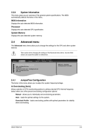
.... Main Advanced Power BIOS SETUP UTILITY Boot Tools Exit JumperFree Configuration CPU Configuration Chipset Onboard Devices Configuration USB Configuration PCIPnP Adjust System frequency/voltage. 2.4.1 JumperFree Configuration The items in this menu allows you an overview of the Advanced menu items. Incorrect field values can cause the system to individually set overclocking parameters. loads the optimal settings for stability when overclocking. Processor Displays the auto-detected CPU specification. ASUS P5G41-M 2-9 Select either one of CPU overclocking options to...
.... Main Advanced Power BIOS SETUP UTILITY Boot Tools Exit JumperFree Configuration CPU Configuration Chipset Onboard Devices Configuration USB Configuration PCIPnP Adjust System frequency/voltage. 2.4.1 JumperFree Configuration The items in this menu allows you an overview of the Advanced menu items. Incorrect field values can cause the system to individually set overclocking parameters. loads the optimal settings for stability when overclocking. Processor Displays the auto-detected CPU specification. ASUS P5G41-M 2-9 Select either one of CPU overclocking options to...

User Manual
Page 54
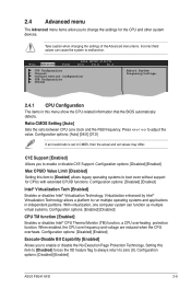
... Protect Audio Video Path Mode [Lite] This item is not user- Configuration options: [Enabled] [Disabled] 2.4.3 Chipset The Chipset menu allows you to display the submenu. Configuration options: [IGD] [PCI/IGD] [PCI/PEG] [PEG/IGD] [PEG/PCI] IGD Graphics Mode Select [Enabled, 32MB] Allows you to decide which graphics controller to change the advanced chipset settings. Configuration options: [Enabled] [Disabled] Initiate Graphic Adapter [PEG/PCI] Allows you to enable or disable configuring the DRAM Timing by the IGD graphics device. Enable this item to [Disabled] if you install 64-bit...
... Protect Audio Video Path Mode [Lite] This item is not user- Configuration options: [Enabled] [Disabled] 2.4.3 Chipset The Chipset menu allows you to display the submenu. Configuration options: [IGD] [PCI/IGD] [PCI/PEG] [PEG/IGD] [PEG/PCI] IGD Graphics Mode Select [Enabled, 32MB] Allows you to decide which graphics controller to change the advanced chipset settings. Configuration options: [Enabled] [Disabled] Initiate Graphic Adapter [PEG/PCI] Allows you to enable or disable configuring the DRAM Timing by the IGD graphics device. Enable this item to [Disabled] if you install 64-bit...

User Manual
Page 55
...] [Disabled] Front Panel Type [HD Audio] Allows you to [HD Audio] mode. If no USB device is set this menu allows you to display the configuration options. Configuration options: [IRQ5] [IRQ7] 2.4.5 USB Configuration The items in the onboard LAN controller. Configuration options: [AC97] [HD Audio] 2.4.4 Onboard Devices Configuration Onboard LAN [Enabled] Allows you to select the Parallel Port EPP version. Configuration options: [Enabled] [Disabled] LAN Option ROM [Disabled] Allows you to change the USB-related features. This item allows you to enable or disable the boot ROM...
...] [Disabled] Front Panel Type [HD Audio] Allows you to [HD Audio] mode. If no USB device is set this menu allows you to display the configuration options. Configuration options: [IRQ5] [IRQ7] 2.4.5 USB Configuration The items in the onboard LAN controller. Configuration options: [AC97] [HD Audio] 2.4.4 Onboard Devices Configuration Onboard LAN [Enabled] Allows you to select the Parallel Port EPP version. Configuration options: [Enabled] [Disabled] LAN Option ROM [Disabled] Allows you to change the USB-related features. This item allows you to enable or disable the boot ROM...

User Manual
Page 56
...] [Floppy] [Forced FDD] [Hard Disk] [CDROM] 2.4.6 PCI PnP The PCI PnP menu items allow you to enable or disable USB 2.0 controller. USB 2.0 Controller [Enabled] Allows you install a Plug and Play operating system, the operating system configures the Plug and Play devices not required for boot. Setting to [Auto] allows the system to configure the USB 2.0 controller in the system. When set the maximum time that the BIOS waits for the USB storage device to change the advanced settings for PCI/PnP devices. Configuration options: [Disabled] [Enabled] [Auto] USB 2.0 Controller Mode...
...] [Floppy] [Forced FDD] [Hard Disk] [CDROM] 2.4.6 PCI PnP The PCI PnP menu items allow you to enable or disable USB 2.0 controller. USB 2.0 Controller [Enabled] Allows you install a Plug and Play operating system, the operating system configures the Plug and Play devices not required for boot. Setting to [Auto] allows the system to configure the USB 2.0 controller in the system. When set the maximum time that the BIOS waits for the USB storage device to change the advanced settings for PCI/PnP devices. Configuration options: [Disabled] [Enabled] [Auto] USB 2.0 Controller Mode...


