

User Manual
Page 1
Motherboard
Motherboard
User Manual
Page 7
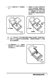
5. 從 CPU PnP 6. 請確認 CPU CPU CPU PnP 保護蓋 CPU CPU CPU CPU 7 A B A B
5. 從 CPU PnP 6. 請確認 CPU CPU CPU PnP 保護蓋 CPU CPU CPU CPU 7 A B A B
User Manual
Page 25
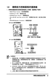
1.8 1 RESET(Reset Switch PLED(Power LED PWRSW(Power Switch IDE_LED(IDE Hard Disk Active LED SPEAKER(Speaker Connector 20-8 pin PLED SPEAKER 1 PANEL1 PLED+ PLED+5V Ground Ground Speaker P5B-E ® IDE_LED+ IDE_LED- SPEAKER、RESET 與 PWRSW IDE_LED 與 PLED PIN1 PIN1 4 25 Ground Reset PWR LED PWR BTN M2N-X F_PANEL HD LED RESET 1 2. 若 LED PIN1)。 3. PWR Ground Reset Ground 10-1 pin IDE_LED RESET PWRSW * Requires an ATX power supply. 紅色 1 表示 PIN1 的位置 PLED+ PLEDPWR GND ...
1.8 1 RESET(Reset Switch PLED(Power LED PWRSW(Power Switch IDE_LED(IDE Hard Disk Active LED SPEAKER(Speaker Connector 20-8 pin PLED SPEAKER 1 PANEL1 PLED+ PLED+5V Ground Ground Speaker P5B-E ® IDE_LED+ IDE_LED- SPEAKER、RESET 與 PWRSW IDE_LED 與 PLED PIN1 PIN1 4 25 Ground Reset PWR LED PWR BTN M2N-X F_PANEL HD LED RESET 1 2. 若 LED PIN1)。 3. PWR Ground Reset Ground 10-1 pin IDE_LED RESET PWRSW * Requires an ATX power supply. 紅色 1 表示 PIN1 的位置 PLED+ PLEDPWR GND ...
User Manual
Page 26
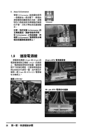
pin ATX 26 Asus Q-Connector 華碩 Q-Connector Q-Connector Q-Connector Q-Connector 1.9 24-pin 或 20-pin 24-pin 4-pin 的 ATX+12V 連接 ATX12V 24-pin ATX 20- 2.
pin ATX 26 Asus Q-Connector 華碩 Q-Connector Q-Connector Q-Connector Q-Connector 1.9 24-pin 或 20-pin 24-pin 4-pin 的 ATX+12V 連接 ATX12V 24-pin ATX 20- 2.

User Manual
Page 31
exe 2 DOS afudos /o[filename filename A:\>afudos /oOLDBIOS1.rom 3. 按下 afudos /oOLDBIOS1.rom AMI Firmware Update Utility - Reading flash ..... All rights reserved. done Write to file...... Version 1.19(ASUS V2.07(03.11.24BB)) Copyright (C) 2002 American Megatrends, Inc. ok A:\> 當 BIOS DOS 31 BIOS 2.1 使用 AFUDOS BIOS AFUDOS DOS BIOS BIOS 程式。AFUDOS BIOS BIOS BIOS 程式 BIOS 程式。 1.2MB BIOS 1 AFUDOS 程式(afudos.
exe 2 DOS afudos /o[filename filename A:\>afudos /oOLDBIOS1.rom 3. 按下 afudos /oOLDBIOS1.rom AMI Firmware Update Utility - Reading flash ..... All rights reserved. done Write to file...... Version 1.19(ASUS V2.07(03.11.24BB)) Copyright (C) 2002 American Megatrends, Inc. ok A:\> 當 BIOS DOS 31 BIOS 2.1 使用 AFUDOS BIOS AFUDOS DOS BIOS BIOS 程式。AFUDOS BIOS BIOS BIOS 程式 BIOS 程式。 1.2MB BIOS 1 AFUDOS 程式(afudos.

User Manual
Page 32
...Utility - Do not turn off power during flash BIOS Reading file ....... done BIOS 5. 當 BIOS DOS A:\>afudos /iP5B-VM DO.ROM AMI Firmware Update Utility - Do not turn off power during flash BIOS Reading file ....... WARNING!! 更新 ...20013;。 BIOS BIOS 2. 將 AFUDOS.EXE BIOS 3 DOS afudos /i[filename filename BIOS 程式。 A:\>afudos /iP5B-VM DO.ROM 4. Version 1.19(ASUS V2.07(03.11.24BB)) Copyright (C) 2002 American Megatrends, Inc. WARNING!! Erasing flash ...... done Verifying flash .... done Reading flash...
...Utility - Do not turn off power during flash BIOS Reading file ....... done BIOS 5. 當 BIOS DOS A:\>afudos /iP5B-VM DO.ROM AMI Firmware Update Utility - Do not turn off power during flash BIOS Reading file ....... WARNING!! 更新 ...20013;。 BIOS BIOS 2. 將 AFUDOS.EXE BIOS 3 DOS afudos /i[filename filename BIOS 程式。 A:\>afudos /iP5B-VM DO.ROM 4. Version 1.19(ASUS V2.07(03.11.24BB)) Copyright (C) 2002 American Megatrends, Inc. WARNING!! Erasing flash ...... done Verifying flash .... done Reading flash...

User Manual
Page 33
...AwardBIOS Flash BIOS AwardBIOS Flash AwardBIOS Flash 程式(AWDFLASH.EXE BIOS AwardBIOS Flash BIOS 程式。 1 http://tw.asus.com BIOS M2N-VM HDMI.bin FAT 32/16 格式的 USB BIOS 2 CD/DVD AwardBIOS Flash BIOS 3 DOS 4. 當 A BIOS...AwardBIOS Flash 5 A awdflash 並按下 鍵。 AwardBIOS Flash Utility for ASUS V1.14 (C) Phoenix Technologies Ltd. PMC Pm49FL004T LPC/FWH File Name to Program: M2A-VM HDMI.bin Message: Do You Want To Save Bios (Y/N) 33 All Rights Reserved For ...
...AwardBIOS Flash BIOS AwardBIOS Flash AwardBIOS Flash 程式(AWDFLASH.EXE BIOS AwardBIOS Flash BIOS 程式。 1 http://tw.asus.com BIOS M2N-VM HDMI.bin FAT 32/16 格式的 USB BIOS 2 CD/DVD AwardBIOS Flash BIOS 3 DOS 4. 當 A BIOS...AwardBIOS Flash 5 A awdflash 並按下 鍵。 AwardBIOS Flash Utility for ASUS V1.14 (C) Phoenix Technologies Ltd. PMC Pm49FL004T LPC/FWH File Name to Program: M2A-VM HDMI.bin Message: Do You Want To Save Bios (Y/N) 33 All Rights Reserved For ...

User Manual
Page 34
... Complete Press to Program: M2A-VM HDMI.bin Programming Flash Memory - OFE00 OK Write OK No Update Write Fail Warning: Don't Turn Off Power Or Reset System! 在更新 BIOS 9 Flash Complete BIOS F1 AwardBIOS Flash Utility for ASUS V1.14 (C) Phoenix Technologies Ltd.... 7 BIOS N BIOS 8 BIOS BIOS AwardBIOS Flash Utility for ASUS V1.14 (C) Phoenix Technologies Ltd. All Rights Reserved For C51PV-MCP51-M2A-VM HDMI-00 DATE:04/13/2006 Flash Type - ...
... Complete Press to Program: M2A-VM HDMI.bin Programming Flash Memory - OFE00 OK Write OK No Update Write Fail Warning: Don't Turn Off Power Or Reset System! 在更新 BIOS 9 Flash Complete BIOS F1 AwardBIOS Flash Utility for ASUS V1.14 (C) Phoenix Technologies Ltd.... 7 BIOS N BIOS 8 BIOS BIOS AwardBIOS Flash Utility for ASUS V1.14 (C) Phoenix Technologies Ltd. All Rights Reserved For C51PV-MCP51-M2A-VM HDMI-00 DATE:04/13/2006 Flash Type - ...
User Manual
Page 2
...permission of their respective companies, and are used only for identification or explanation and to the owners' benefit, without intent to infringe. ASUS PROVIDES THIS MANUAL "AS IS" WITHOUT WARRANTY OF ANY KIND, EITHER EXPRESS OR IMPLIED, INCLUDING BUT NOT LIMITED TO THE IMPLIED ... OF MERCHANTABILITY OR FITNESS FOR A PARTICULAR PURPOSE. All Rights Reserved. or (2) the serial number of alteration is defaced or missing. ASUS ASSUMES NO RESPONSIBILITY OR LIABILITY FOR ANY ERRORS OR INACCURACIES THAT MAY APPEAR IN THIS MANUAL, INCLUDING THE PRODUCTS AND SOFTWARE DESCRIBED IN IT...
...permission of their respective companies, and are used only for identification or explanation and to the owners' benefit, without intent to infringe. ASUS PROVIDES THIS MANUAL "AS IS" WITHOUT WARRANTY OF ANY KIND, EITHER EXPRESS OR IMPLIED, INCLUDING BUT NOT LIMITED TO THE IMPLIED ... OF MERCHANTABILITY OR FITNESS FOR A PARTICULAR PURPOSE. All Rights Reserved. or (2) the serial number of alteration is defaced or missing. ASUS ASSUMES NO RESPONSIBILITY OR LIABILITY FOR ANY ERRORS OR INACCURACIES THAT MAY APPEAR IN THIS MANUAL, INCLUDING THE PRODUCTS AND SOFTWARE DESCRIBED IN IT...
User Manual
Page 3
Contents Notices...vi Safety information vii P5E-VM DO specifications summary x Chapter 1: Product introduction 1.1 Welcome 1-2 1.2 Package contents 1-2 1.3 Special features 1-2 1.3.1 Product highlights 1-2 1.3.2 ASUS Features 1-4 1.3.3 ASUS Special Features 1-5 1.3.4 ASUS Intelligent Overclocking Features 1-6 1.4 Before you proceed 1-7 1.5 Motherboard overview 1-8 1.5.1 Placement direction 1-8 1.5.2 Screw holes 1-8 1.5.3 Motherboard layout 1-9 1.5.4 Layout contents 1-10 1.6 Central Processing Unit (CPU 1-12 1.6.1 Installing the CPU 1-...
Contents Notices...vi Safety information vii P5E-VM DO specifications summary x Chapter 1: Product introduction 1.1 Welcome 1-2 1.2 Package contents 1-2 1.3 Special features 1-2 1.3.1 Product highlights 1-2 1.3.2 ASUS Features 1-4 1.3.3 ASUS Special Features 1-5 1.3.4 ASUS Intelligent Overclocking Features 1-6 1.4 Before you proceed 1-7 1.5 Motherboard overview 1-8 1.5.1 Placement direction 1-8 1.5.2 Screw holes 1-8 1.5.3 Motherboard layout 1-9 1.5.4 Layout contents 1-10 1.6 Central Processing Unit (CPU 1-12 1.6.1 Installing the CPU 1-...

User Manual
Page 4
... 1.10.1 Rear panel connectors 1-29 1.10.2 Internal connectors 1-30 Chapter 2: BIOS setup 2.1 Managing and updating your BIOS 2-2 2.1.1 Creating a bootable floppy disk 2-2 2.1.2 ASUS EZ Flash 2 utility 2-3 2.1.3 AFUDOS utility 2-4 2.1.4 ASUS CrashFree BIOS 3 utility 2-6 2.1.5 ASUS Update utility 2-8 2.2 BIOS setup program 2-11 2.2.1 BIOS menu screen 2-12 2.2.2 Menu bar 2-12 2.2.3 Navigation keys 2-12 2.2.4 Menu items 2-13 2.2.5 Sub-menu...
... 1.10.1 Rear panel connectors 1-29 1.10.2 Internal connectors 1-30 Chapter 2: BIOS setup 2.1 Managing and updating your BIOS 2-2 2.1.1 Creating a bootable floppy disk 2-2 2.1.2 ASUS EZ Flash 2 utility 2-3 2.1.3 AFUDOS utility 2-4 2.1.4 ASUS CrashFree BIOS 3 utility 2-6 2.1.5 ASUS Update utility 2-8 2.2 BIOS setup program 2-11 2.2.1 BIOS menu screen 2-12 2.2.2 Menu bar 2-12 2.2.3 Navigation keys 2-12 2.2.4 Menu items 2-13 2.2.5 Sub-menu...

User Manual
Page 5
... APIC support 2-35 2.5.5 APM Configuration 2-36 2.5.6 Hardware Monitor 2-37 2.6 Boot menu 2-38 2.6.1 Boot Device Priority 2-38 2.6.2 Boot Settings Configuration 2-39 2.6.3 Security 2-40 2.7 Tools menu 2-42 ASUS EZ Flash 2 2-42 2.8 Exit menu 2-43 Chapter 3: Software support 3.1 Installing an operating system 3-2 3.2 Support CD information 3-2 3.2.1 Running the support CD 3-2 3.2.2 Drivers menu 3-3 3.2.3 Utilities menu 3-4 3.2.4 Make...
... APIC support 2-35 2.5.5 APM Configuration 2-36 2.5.6 Hardware Monitor 2-37 2.6 Boot menu 2-38 2.6.1 Boot Device Priority 2-38 2.6.2 Boot Settings Configuration 2-39 2.6.3 Security 2-40 2.7 Tools menu 2-42 ASUS EZ Flash 2 2-42 2.8 Exit menu 2-43 Chapter 3: Software support 3.1 Installing an operating system 3-2 3.2 Support CD information 3-2 3.2.1 Running the support CD 3-2 3.2.2 Drivers menu 3-3 3.2.3 Utilities menu 3-4 3.2.4 Make...
User Manual
Page 6
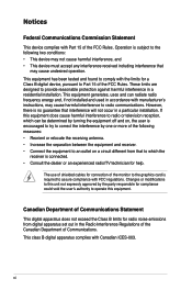
Changes or modifications to Part 15 of the FCC Rules. Canadian Department of Communications Statement This digital apparatus does not exceed the Class B limits for compliance could void the user's authority to operate this equipment does cause harmful interference to radio or television reception, which can radiate radio frequency energy and, if not installed and used in the Radio Interference Regulations of the Canadian Department of shielded cables for help. These limits are designed to radio communications. The use of Communications. However, there is subject to the ...
Changes or modifications to Part 15 of the FCC Rules. Canadian Department of Communications Statement This digital apparatus does not exceed the Class B limits for compliance could void the user's authority to operate this equipment does cause harmful interference to radio or television reception, which can radiate radio frequency energy and, if not installed and used in the Radio Interference Regulations of the Canadian Department of shielded cables for help. These limits are designed to radio communications. The use of Communications. However, there is subject to the ...

User Manual
Page 7
Contact a qualified service technician or your area. If you are not sure about the voltage of the electrical outlet you add a device. • Before connecting or removing signal cables from the motherboard, ensure that all the manuals that came with the product, contact a qualified service technician or your dealer immediately. • To avoid short circuits, keep paper clips, screws, and staples away from connectors, slots, sockets and circuitry. • Avoid dust, humidity, and temperature extremes. Check local regulations for the devices are unplugged before the ...
Contact a qualified service technician or your area. If you are not sure about the voltage of the electrical outlet you add a device. • Before connecting or removing signal cables from the motherboard, ensure that all the manuals that came with the product, contact a qualified service technician or your dealer immediately. • To avoid short circuits, keep paper clips, screws, and staples away from connectors, slots, sockets and circuitry. • Avoid dust, humidity, and temperature extremes. Check local regulations for the devices are unplugged before the ...
User Manual
Page 8
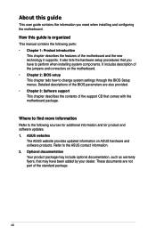
... to the following parts: • Chapter 1: Product introduction This chapter describes the features of the jumpers and connectors on ASUS hardware and software products. viii ASUS websites The ASUS website provides updated information on the motherboard. • Chapter 2: BIOS setup This chapter tells how to the... ASUS contact information. 2. Optional documentation Your product package may include optional documentation, such as warranty flyers, that you need when ...
... to the following parts: • Chapter 1: Product introduction This chapter describes the features of the jumpers and connectors on ASUS hardware and software products. viii ASUS websites The ASUS website provides updated information on the motherboard. • Chapter 2: BIOS setup This chapter tells how to the... ASUS contact information. 2. Optional documentation Your product package may include optional documentation, such as warranty flyers, that you need when ...
User Manual
Page 9
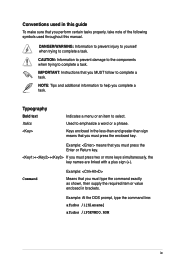
IMPORTANT: Instructions that you MUST follow to help you perform certain tasks properly, take note of the following symbols used in this manual. Keys enclosed in brackets. CAUTION: Information to prevent damage to the components when trying to select. Typography Bold text Italics Indicates a menu or an item to complete a task. Command Example: Means that you must press the Enter or Return key. ++ If you must press two or more keys simultaneously, the key names are linked with a plus sign (+). Example: means that you must type the command exactly as shown, then ...
IMPORTANT: Instructions that you MUST follow to help you perform certain tasks properly, take note of the following symbols used in this manual. Keys enclosed in brackets. CAUTION: Information to prevent damage to the components when trying to select. Typography Bold text Italics Indicates a menu or an item to complete a task. Command Example: Means that you must press the Enter or Return key. ++ If you must press two or more keys simultaneously, the key names are linked with a plus sign (+). Example: means that you must type the command exactly as shown, then ...
User Manual
Page 10
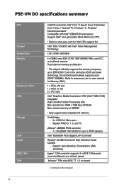
... (one at midboard; Support RAID 0, 1, 5, and 10 JMicron® JMB368 PATA controller - 1 x UltraDMA 133/100/66 for up to DDR2 800. P5E-VM DO specifications summary CPU Chipset System Bus Memory Expansion Slots VGA Storage LAN Audio IEEE 1394 TPM LGA775 socket for Intel® Core™2 Quad...174; Extreme processor* Compatible with Intel® 05B/05A/06 processors Support Intel® next generation 45nm Multi-core CPU. * Refer to www.asus.com for Intel CPU support list Intel® Q35 / ICH9DO with Max resolution to 2 PATA devices Intel® 82566DM PCIe Gigabit LAN Controller ...
... (one at midboard; Support RAID 0, 1, 5, and 10 JMicron® JMB368 PATA controller - 1 x UltraDMA 133/100/66 for up to DDR2 800. P5E-VM DO specifications summary CPU Chipset System Bus Memory Expansion Slots VGA Storage LAN Audio IEEE 1394 TPM LGA775 socket for Intel® Core™2 Quad...174; Extreme processor* Compatible with Intel® 05B/05A/06 processors Support Intel® next generation 45nm Multi-core CPU. * Refer to www.asus.com for Intel CPU support list Intel® Q35 / ICH9DO with Max resolution to 2 PATA devices Intel® 82566DM PCIe Gigabit LAN Controller ...
User Manual
Page 11
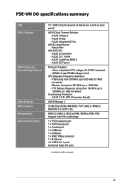
P5E-VM DO specifications summary USB ASUS Features ASUS Exclusive Overclocking Features Other Features BIOS Features Manageability Back Panel I /O ports (continued on the next page) xi ASUS O.C. ASUS CrashFree BIOS 3 - ASUS AI Nap - ASUS EZ Flash 2 Precision Tweaker: - Noise Filter ASUS EZ DIY: - FSB tuning from 100 MHz up to 150 MHz at 1MHz - increment - Profile - vCore: Adjustable CPU voltage...
P5E-VM DO specifications summary USB ASUS Features ASUS Exclusive Overclocking Features Other Features BIOS Features Manageability Back Panel I /O ports (continued on the next page) xi ASUS O.C. ASUS CrashFree BIOS 3 - ASUS AI Nap - ASUS EZ Flash 2 Precision Tweaker: - Noise Filter ASUS EZ DIY: - FSB tuning from 100 MHz up to 150 MHz at 1MHz - increment - Profile - vCore: Adjustable CPU voltage...
User Manual
Page 12
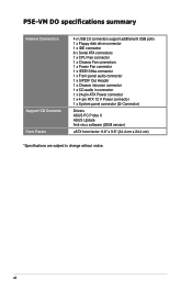
xii P5E-VM DO specifications summary Internal Connectors Support CD Contents Form Factor 4 x USB 2.0 connectors support additional 8 USB ports 1 x Floppy disk drive connector 1 x IDE connector 6 x Serial ATA connectors 1 x ... 1 x S/PDIF Out Header 1 x Chassis intrusion connector 1 x CD audio in connector 1 x 24-pin ATX Power connector 1 x 4-pin ATX 12 V Power connector 1 x System panel connector (Q-Connector) Drivers ASUS PC Probe II ASUS Update Anti-virus software (OEM version) uATX form factor: 9.6" x 9.6" (24.4 cm x 24.4 cm) *Specifications are subject to change without notice.
xii P5E-VM DO specifications summary Internal Connectors Support CD Contents Form Factor 4 x USB 2.0 connectors support additional 8 USB ports 1 x Floppy disk drive connector 1 x IDE connector 6 x Serial ATA connectors 1 x ... 1 x S/PDIF Out Header 1 x Chassis intrusion connector 1 x CD audio in connector 1 x 24-pin ATX Power connector 1 x 4-pin ATX 12 V Power connector 1 x System panel connector (Q-Connector) Drivers ASUS PC Probe II ASUS Update Anti-virus software (OEM version) uATX form factor: 9.6" x 9.6" (24.4 cm x 24.4 cm) *Specifications are subject to change without notice.

User Manual
Page 13
This chapter describes the motherboard features and the new technologies it supports. 1Product introduction
This chapter describes the motherboard features and the new technologies it supports. 1Product introduction
