P5B-VM English Edition User's Manual
Page 4
... 2.1 Managing and updating your BIOS 2-2 2.1.1 Creating a bootable floppy disk 2-2 2.1.2 ASUS EZ Flash 2 utility 2-3 2.1.3 AFUDOS utility 2-4 2.1.4 ASUS CrashFree BIOS 3 utility 2-6 2.1.5 ASUS Update utility 2-8 2.2 BIOS setup program 2-11 2.2.1 BIOS menu screen 2-12 2.2.2 Menu bar 2-12 2.2.3 Navigation keys 2-12 2.2.4 Menu items 2-13 2.2.5 Sub-menu items 2-13 2.2.6 Configuration fields 2-13 2.2.7 Pop-up window 2-13 2.2.8 Scroll bar 2-...
... 2.1 Managing and updating your BIOS 2-2 2.1.1 Creating a bootable floppy disk 2-2 2.1.2 ASUS EZ Flash 2 utility 2-3 2.1.3 AFUDOS utility 2-4 2.1.4 ASUS CrashFree BIOS 3 utility 2-6 2.1.5 ASUS Update utility 2-8 2.2 BIOS setup program 2-11 2.2.1 BIOS menu screen 2-12 2.2.2 Menu bar 2-12 2.2.3 Navigation keys 2-12 2.2.4 Menu items 2-13 2.2.5 Sub-menu items 2-13 2.2.6 Configuration fields 2-13 2.2.7 Pop-up window 2-13 2.2.8 Scroll bar 2-...
P5B-VM English Edition User's Manual
Page 8
... your dealer. Where to find more information Refer to the ASUS contact information. 2. Detailed descriptions of the BIOS parameters are not part of the jumpers and connectors on ASUS hardware and software products. ASUS websites The ASUS website provides updated information on the motherboard. • Chapter 2: BIOS setup This chapter tells how to perform when installing system...
... your dealer. Where to find more information Refer to the ASUS contact information. 2. Detailed descriptions of the BIOS parameters are not part of the jumpers and connectors on ASUS hardware and software products. ASUS websites The ASUS website provides updated information on the motherboard. • Chapter 2: BIOS setup This chapter tells how to perform when installing system...
P5B-VM English Edition User's Manual
Page 11
...connector 1 x CD audio in connector 1 x 24-pin ATX power connector 1 x 4-pin ATX 12 V power connector 1 x HD Audio Digital Header System panel connector 8 Mb Flash ROM, AMI BIOS, PnP, DMI 2.0, WfM2.0, SM BIOS 2.3, ACPI 2.0a, ASUS EZ Flash 2, ASUS CrashFree BIOS 3 WfM 2.0, DMI 2.0, WOL by PME, WOR by ...PME, PXE Device drivers ASUS PC Probe II ASUS Update Anti-virus software (OEM version) Micro-ATX form factor: 9.6 in x 9.6 in...
...connector 1 x CD audio in connector 1 x 24-pin ATX power connector 1 x 4-pin ATX 12 V power connector 1 x HD Audio Digital Header System panel connector 8 Mb Flash ROM, AMI BIOS, PnP, DMI 2.0, WfM2.0, SM BIOS 2.3, ACPI 2.0a, ASUS EZ Flash 2, ASUS CrashFree BIOS 3 WfM 2.0, DMI 2.0, WOL by PME, WOR by ...PME, PXE Device drivers ASUS PC Probe II ASUS Update Anti-virus software (OEM version) Micro-ATX form factor: 9.6 in x 9.6 in...
P5B-VM English Edition User's Manual
Page 17
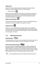
... you easy ways to install computer components, update the BIOS or back up your screen. ASUS EZ Flash 2 EZ Flash 2 is required prior using an OS-based flash utility. This unique module eliminates the trouble of the motherboard BIOS allows automatic re-setting to the BIOS default settings in case the system hangs due to...
... you easy ways to install computer components, update the BIOS or back up your screen. ASUS EZ Flash 2 EZ Flash 2 is required prior using an OS-based flash utility. This unique module eliminates the trouble of the motherboard BIOS allows automatic re-setting to the BIOS default settings in case the system hangs due to...
P5B-VM English Edition User's Manual
Page 20
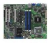
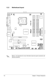
24.5cm (9.6in) 1.5.3 Motherboard layout PS/2KBM S T: Mouse B: Keyboard ESATA KBPWR PWR_FAN 24.5cm (9.6in) CPU_FAN LGA775 CHA_FAN1 Super I/O DDR2 DIMM_B1 (64 bit,240-pin module) DDR2 DIMM_B2 (64 ... RTL8111B Intel G965MCH SATA_RAID1 JMicron JMB363 TSB43AB22A AD1988 AAFP CD SPDIF_OUT PCIEX16 PCI1 SB_PWR PCI2 PCIEX4_1 IE1394_2 ADH CR2032 3V Lithium Cell CMOS Power 8Mb BIOS PRI_EIDE COM1 Intel ICH8 SATA1 SATA2 USB56 SATA3 SATA4 USB78 PANEL CHASSIS USB910 CLRTC Refer to 1.10 Connectors for more information about rear panel connectors...
24.5cm (9.6in) 1.5.3 Motherboard layout PS/2KBM S T: Mouse B: Keyboard ESATA KBPWR PWR_FAN 24.5cm (9.6in) CPU_FAN LGA775 CHA_FAN1 Super I/O DDR2 DIMM_B1 (64 bit,240-pin module) DDR2 DIMM_B2 (64 ... RTL8111B Intel G965MCH SATA_RAID1 JMicron JMB363 TSB43AB22A AD1988 AAFP CD SPDIF_OUT PCIEX16 PCI1 SB_PWR PCI2 PCIEX4_1 IE1394_2 ADH CR2032 3V Lithium Cell CMOS Power 8Mb BIOS PRI_EIDE COM1 Intel ICH8 SATA1 SATA2 USB56 SATA3 SATA4 USB78 PANEL CHASSIS USB910 CLRTC Refer to 1.10 Connectors for more information about rear panel connectors...
P5B-VM English Edition User's Manual
Page 35
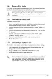
See Chapter 4 for information on the system and change the necessary BIOS settings, if any. Refer to the card. Remove the system unit cover (if your motherboard is completely seated on the next page. 3. Assign an IRQ to the table on the next page for the card. 2. Install the software ... the expansion cards that you intend to the tables on the slot. 5. Make sure to the chassis with the screw you removed earlier. 6. ASUS P5B-VM 1-23 Secure the card to unplug the power cord before adding or removing expansion cards. Align the card connector with it by adjusting...
See Chapter 4 for information on the system and change the necessary BIOS settings, if any. Refer to the card. Remove the system unit cover (if your motherboard is completely seated on the next page. 3. Assign an IRQ to the table on the next page for the card. 2. Install the software ... the expansion cards that you intend to the tables on the slot. 5. Make sure to the chassis with the screw you removed earlier. 6. ASUS P5B-VM 1-23 Secure the card to unplug the power cord before adding or removing expansion cards. Align the card connector with it by adjusting...
P5B-VM English Edition User's Manual
Page 38
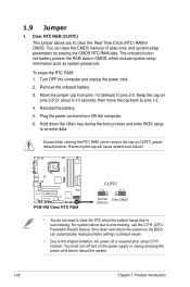
...prior using C.P.R. For system failure due to pins 1-2. 4. Remove the onboard battery. 3. Reinstall the battery. 5. Hold down and reboot the system so the BIOS can clear the CMOS memory of date, time, and system setup parameters by erasing the CMOS RTC RAM data. Except when clearing the RTC RAM...before reboot the system. 1-26 Chapter 1: Product introduction To erase the RTC RAM: 1. Shut down the key during the boot process and enter BIOS setup to clear the Real Time Clock (RTC) RAM in CMOS, which include system setup information such as system passwords. You must turn ON ...
...prior using C.P.R. For system failure due to pins 1-2. 4. Remove the onboard battery. 3. Reinstall the battery. 5. Hold down and reboot the system so the BIOS can clear the CMOS memory of date, time, and system setup parameters by erasing the CMOS RTC RAM data. Except when clearing the RTC RAM...before reboot the system. 1-26 Chapter 1: Product introduction To erase the RTC RAM: 1. Shut down the key during the boot process and enter BIOS setup to clear the Real Time Clock (RTC) RAM in CMOS, which include system setup information such as system passwords. You must turn ON ...

P5B-VM English Edition User's Manual
Page 39
P5B-VM KBPWR 2 1 +5V (Default) 3 2 +5VSB R P5B-VM Keyboard Power Setting ASUS P5B-VM 1-27 2. Set this jumper to pins 2-3 (+5VSB) to wake up the computer when you to enable or disable the keyboard wake-up feature. This feature requires an ATX power supply that can supply at least 1A on the keyboard (the default is the Space Bar). Keyboard power (3-pin KBPWR) This jumper allows you press a key on the +5VSB lead, and a corresponding setting in the BIOS.
P5B-VM KBPWR 2 1 +5V (Default) 3 2 +5VSB R P5B-VM Keyboard Power Setting ASUS P5B-VM 1-27 2. Set this jumper to pins 2-3 (+5VSB) to wake up the computer when you to enable or disable the keyboard wake-up feature. This feature requires an ATX power supply that can supply at least 1A on the keyboard (the default is the Space Bar). Keyboard power (3-pin KBPWR) This jumper allows you press a key on the +5VSB lead, and a corresponding setting in the BIOS.

P5B-VM English Edition User's Manual
Page 41
...make sure that you can combine with an external Serial ATA 3.0 Gb/s device to [RAID]. This port is for connecting USB 2.0 devices. 13. ASUS P5B-VM 1-29 Rear Speaker Out - 6-channel 8-channel Line In Front Speaker Out Mic In Center/Subwoofer Rear Speaker Out - VGA port. External...Serial ATA signal cable and installed Serial ATA hard disk drives; See section "2.4.5 Onboard Device Configuration" for the function of the audio ports in the BIOS to configure a RAID 0, RAID 1, or JBOD set through the onboard JMicron SATA RAID controller. This port is for connecting USB 2.0 devices. ...
...make sure that you can combine with an external Serial ATA 3.0 Gb/s device to [RAID]. This port is for connecting USB 2.0 devices. 13. ASUS P5B-VM 1-29 Rear Speaker Out - 6-channel 8-channel Line In Front Speaker Out Mic In Center/Subwoofer Rear Speaker Out - VGA port. External...Serial ATA signal cable and installed Serial ATA hard disk drives; See section "2.4.5 Onboard Device Configuration" for the function of the audio ports in the BIOS to configure a RAID 0, RAID 1, or JBOD set through the onboard JMicron SATA RAID controller. This port is for connecting USB 2.0 devices. ...
P5B-VM English Edition User's Manual
Page 45
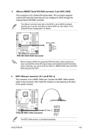
...cable to this connector, then install the module to build a RAID set using Serial ATA hard disks, make sure that you can configure for details. ASUS P5B-VM 1-33 IEEE 1394a port connector (10-1 pin IE1394_2) This connector is for a IEEE 1394a port. This connector supports a Serial ATA ...hard disk drive that you cannot enter the JMicron® JMB363 RAID utility and SATA BIOS setup during POST. 5. SATA_RAID1 GND RSATA _RXN1 RSATA _RXP1 GND RSATA _TXN1 RSATA _TXP1 GND P5B-VM SATA RAID Connector Before creating a RAID set ....
...cable to this connector, then install the module to build a RAID set using Serial ATA hard disks, make sure that you can configure for details. ASUS P5B-VM 1-33 IEEE 1394a port connector (10-1 pin IE1394_2) This connector is for a IEEE 1394a port. This connector supports a Serial ATA ...hard disk drive that you cannot enter the JMicron® JMB363 RAID utility and SATA BIOS setup during POST. 5. SATA_RAID1 GND RSATA _RXN1 RSATA _RXP1 GND RSATA _TXN1 RSATA _TXP1 GND P5B-VM SATA RAID Connector Before creating a RAID set ....
P5B-VM English Edition User's Manual
Page 48
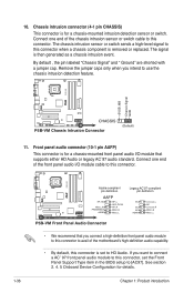
... with a jumper cap. 10. The signal is removed or replaced. Connect one end of the motherboard's high-definition audio capability. • By default, this connector is set the Front Panel Support Type item in the BIOS setup to this connector, set to use the chassis intrusion detection feature. Front panel audio connector...
... with a jumper cap. 10. The signal is removed or replaced. Connect one end of the motherboard's high-definition audio capability. • By default, this connector is set the Front Panel Support Type item in the BIOS setup to this connector, set to use the chassis intrusion detection feature. Front panel audio connector...
P5B-VM English Edition User's Manual
Page 50
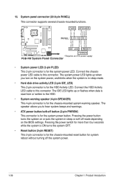
... Ground Reset Ground 13. PLED SPEAKER PA NEL IDE_LED RESET PWRSW * Requires an ATX power supply P5B-VM System Panel Connector • System power LED (2-pin PLED)... the HDD Activity LED cable to this connector. Pressing the power button turns the system on the BIOS settings. The system power LED lights up or flashes when data is read from or written to hear system beeps ...and warnings. • ATX power button/soft-off the system power. 1-38 Chapter 1: Product introduction Pressing the power switch for more...
... Ground Reset Ground 13. PLED SPEAKER PA NEL IDE_LED RESET PWRSW * Requires an ATX power supply P5B-VM System Panel Connector • System power LED (2-pin PLED)... the HDD Activity LED cable to this connector. Pressing the power button turns the system on the BIOS settings. The system power LED lights up or flashes when data is read from or written to hear system beeps ...and warnings. • ATX power button/soft-off the system power. 1-38 Chapter 1: Product introduction Pressing the power switch for more...
P5B-VM English Edition User's Manual
Page 53
Detailed descriptions of the BIOS parameters are also provided. 2 BIOS setup This chapter tells how to change the system settings through the BIOS Setup menus.
Detailed descriptions of the BIOS parameters are also provided. 2 BIOS setup This chapter tells how to change the system settings through the BIOS Setup menus.
P5B-VM English Edition User's Manual
Page 54
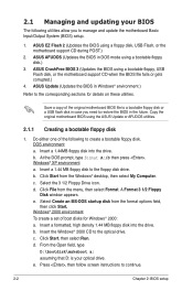
...1/2 Floppy Disk window appears. e. Windows® 2000 environment To create a set of the original motherboard BIOS file to a bootable floppy disk or a USB flash disk in DOS mode using the ASUS Update or AFUDOS utilities. 2.1.1 Creating a bootable floppy disk 1. Insert a formatted, high density 1.... A:/S then press . b. Click Start, then select Run. b. ASUS EZ Flash 2 (Updates the BIOS using a bootable floppy, USB Flash disk, or the motherboard support CD when the BIOS file fails or gets corrupted.) 4. ASUS CrashFree BIOS 3 (Updates the BIOS using a floppy disk, USB Flash, or the...
...1/2 Floppy Disk window appears. e. Windows® 2000 environment To create a set of the original motherboard BIOS file to a bootable floppy disk or a USB flash disk in DOS mode using the ASUS Update or AFUDOS utilities. 2.1.1 Creating a bootable floppy disk 1. Insert a formatted, high density 1.... A:/S then press . b. Click Start, then select Run. b. ASUS EZ Flash 2 (Updates the BIOS using a bootable floppy, USB Flash disk, or the motherboard support CD when the BIOS file fails or gets corrupted.) 4. ASUS CrashFree BIOS 3 (Updates the BIOS using a floppy disk, USB Flash, or the...
P5B-VM English Edition User's Manual
Page 55
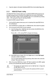
... or a USB flash disk, then restart the system. 3. Then press . 4. Copy the original or the latest motherboard BIOS file to the bootable floppy disk. 2.1.2 ASUS EZ Flash 2 utility The ASUS EZ Flash 2 feature allows you to update the BIOS without having to the floppy disk drive or the USB port. Press + during the Power-On...
... or a USB flash disk, then restart the system. 3. Then press . 4. Copy the original or the latest motherboard BIOS file to the bootable floppy disk. 2.1.2 ASUS EZ Flash 2 utility The ASUS EZ Flash 2 feature allows you to update the BIOS without having to the floppy disk drive or the USB port. Press + during the Power-On...
P5B-VM English Edition User's Manual
Page 56
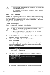
.... 2. A:\>afudos /oOLDBIOS1.rom AMI Firmware Update Utility - Version 1.19(ASUS V2.07(03.11.24BB)) Copyright (C) 2002 American Megatrends, Inc. Copy the AFUDOS utility (afudos.exe) from the motherboard support CD to file...... Reading flash ..... Copying the current BIOS To copy the current BIOS file using a bootable floppy disk with FAT 32/16 format...
.... 2. A:\>afudos /oOLDBIOS1.rom AMI Firmware Update Utility - Version 1.19(ASUS V2.07(03.11.24BB)) Copyright (C) 2002 American Megatrends, Inc. Copy the AFUDOS utility (afudos.exe) from the motherboard support CD to file...... Reading flash ..... Copying the current BIOS To copy the current BIOS file using a bootable floppy disk with FAT 32/16 format...
P5B-VM English Edition User's Manual
Page 57
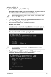
... Firmware Update Utility - done Verifying flash .... done Advance Check ...... Visit the ASUS website (www.asus.com) and download the latest BIOS file for the motherboard. Do not turn off power during flash BIOS Reading file ....... Erasing flash ...... Updating the BIOS file To update the BIOS file using the AFUDOS utility: 1. Boot the system in DOS mode, then...
... Firmware Update Utility - done Verifying flash .... done Advance Check ...... Visit the ASUS website (www.asus.com) and download the latest BIOS file for the motherboard. Do not turn off power during flash BIOS Reading file ....... Erasing flash ...... Updating the BIOS file To update the BIOS file using the AFUDOS utility: 1. Boot the system in DOS mode, then...
P5B-VM English Edition User's Manual
Page 58
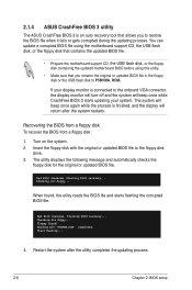
... Recovering the BIOS from a floppy disk To recover the BIOS from a floppy disk: 1. Starting BIOS recovery... Floppy found , the utility reads the BIOS file and starts flashing the corrupted BIOS file. Restart the system after the system restarts. 2.1.4 ASUS CrashFree BIOS 3 utility The ASUS CrashFree BIOS 3 is ... update a corrupted BIOS file using the motherboard support CD, the USB flash disk, or the floppy disk that contains the updated BIOS file. • Prepare the motherboard support CD, the USB flash disk, or the floppy disk containing the updated motherboard BIOS before using this...
... Recovering the BIOS from a floppy disk To recover the BIOS from a floppy disk: 1. Starting BIOS recovery... Floppy found , the utility reads the BIOS file and starts flashing the corrupted BIOS file. Restart the system after the system restarts. 2.1.4 ASUS CrashFree BIOS 3 utility The ASUS CrashFree BIOS 3 is ... update a corrupted BIOS file using the motherboard support CD, the USB flash disk, or the floppy disk that contains the updated BIOS file. • Prepare the motherboard support CD, the USB flash disk, or the floppy disk containing the updated motherboard BIOS before using this...

P5B-VM English Edition User's Manual
Page 59
...-ROM found ! Visit the ASUS website (www.asus.com) to the optical drive. 3. Completed. Recovering the BIOS from the support CD To recover the BIOS from the floppy disk drive, then turn on the system. 3. The utility displays the following message and automatically checks the floppy disk for this motherboard. Checking for the original or...
...-ROM found ! Visit the ASUS website (www.asus.com) to the optical drive. 3. Completed. Recovering the BIOS from the support CD To recover the BIOS from the floppy disk drive, then turn on the system. 3. The utility displays the following message and automatically checks the floppy disk for this motherboard. Checking for the original or...
P5B-VM English Edition User's Manual
Page 60
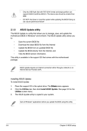
... that comes with FAT 32/16 format and single partition can cause system boot failure! 2.1.5 ASUS Update utility The ASUS Update is a utility that allows you to manage, save, and update the motherboard BIOS in Windows® environment. The ASUS Update utility is available in the optical drive. This utility is copied to : • Save...
... that comes with FAT 32/16 format and single partition can cause system boot failure! 2.1.5 ASUS Update utility The ASUS Update is a utility that allows you to manage, save, and update the motherboard BIOS in Windows® environment. The ASUS Update utility is available in the optical drive. This utility is copied to : • Save...


