P5A User Manual
Page 2
... repair, modification of alteration is authorized in the manual revision number. For previous or updated manuals, BIOS, drivers, or product release information, contact ASUS at http://www.asus.com.tw or through any means, except documentation kept by the third digit in writing by...OR PRODUCT. All Rights Reserved. Manual updates are registered trademarks of ASUSTeK COMPUTER INC. ("ASUS"). Product Name: ASUS P5A Manual Revision: 1.07 E382 Release Date: May 1999 2 ASUS P5A User's Manual Product warranty or service will not be registered trademarks or copyrights of their ...
... repair, modification of alteration is authorized in the manual revision number. For previous or updated manuals, BIOS, drivers, or product release information, contact ASUS at http://www.asus.com.tw or through any means, except documentation kept by the third digit in writing by...OR PRODUCT. All Rights Reserved. Manual updates are registered trademarks of ASUSTeK COMPUTER INC. ("ASUS"). Product Name: ASUS P5A Manual Revision: 1.07 E382 Release Date: May 1999 2 ASUS P5A User's Manual Product warranty or service will not be registered trademarks or copyrights of their ...

P5A User Manual
Page 4
... and Hardware Monitor 24 Accelerated Graphics Port 24 5. INSTALLATION 12 ASUS P5A Motherboard Layout 12 Installation Steps 14 1. BIOS SOFTWARE 36 Main Menu 36 Managing and Updating Your Motherboard's BIOS 38 6. FEATURES 8 ASUS P5A Motherboard 8 Introduction to ASUS Smart Series Motherboards 9 Parts of Power Management Setup 49 4 ASUS P5A User's Manual CONTENTS I. System Memory (DIMM 19 DIMM Memory Installation...
... and Hardware Monitor 24 Accelerated Graphics Port 24 5. INSTALLATION 12 ASUS P5A Motherboard Layout 12 Installation Steps 14 1. BIOS SOFTWARE 36 Main Menu 36 Managing and Updating Your Motherboard's BIOS 38 6. FEATURES 8 ASUS P5A Motherboard 8 Introduction to ASUS Smart Series Motherboards 9 Parts of Power Management Setup 49 4 ASUS P5A User's Manual CONTENTS I. System Memory (DIMM 19 DIMM Memory Installation...

P5A User Manual
Page 5
...Features 66 Software Driver Support 66 Question and Answer 66 APPENDIX 67 Glossary 67 ASUS P5A User's Manual 5 ASUS CIDB 63 The ASUS CIDB Chassis Sensor 63 Using the ASUS CIDB 63 Setting up the ASUS CIDB 64 ASUS CIDB Additional Considerations 64 VII. CONTENTS PNP and PCI Setup 52 Details of PNP... and PCI Setup 52 Load BIOS Defaults 54 Load Setup Defaults 54 Supervisor Password and User Password 55 IDE HDD Auto ...
...Features 66 Software Driver Support 66 Question and Answer 66 APPENDIX 67 Glossary 67 ASUS P5A User's Manual 5 ASUS CIDB 63 The ASUS CIDB Chassis Sensor 63 Using the ASUS CIDB 63 Setting up the ASUS CIDB 64 ASUS CIDB Additional Considerations 64 VII. CONTENTS PNP and PCI Setup 52 Details of PNP... and PCI Setup 52 Load BIOS Defaults 54 Load Setup Defaults 54 Supervisor Password and User Password 55 IDE HDD Auto ...

P5A User Manual
Page 7
... with drivers and utilities (1) User's Manual ASUS CIDB chassis sensor module (optional) ASUS IrDA-compliant infrared module (optional) ASUS PCI-L101 Wake-On-LAN 10/100 Ethernet Card (optional) ASUS P5A User's Manual 7 ASUS CIDB Installation of the ASUS CIDB Chassis Sensor (optional) VII. I . Introduction Manual information and checklist II. BIOS Software Instructions on the included support software...
... with drivers and utilities (1) User's Manual ASUS CIDB chassis sensor module (optional) ASUS IrDA-compliant infrared module (optional) ASUS PCI-L101 Wake-On-LAN 10/100 Ethernet Card (optional) ASUS P5A User's Manual 7 ASUS CIDB Installation of the ASUS CIDB Chassis Sensor (optional) VII. I . Introduction Manual information and checklist II. BIOS Software Instructions on the included support software...

P5A User Manual
Page 8
... Mouse, IrDA Connector: Supports an optional cable and bracket set . 8 ASUS P5A User's Manual II. These new SDRAMs are necessary to monitor your system's vital components/activities, such as Tape Backup and CD-ROM drives. BIOS supports IDE CD-ROM or SCSI device boot-up to an unused expansion slot... on the system chassis. FEATURES ASUS P5A Motherboard • ALi AGPset: ALi® (Acer Laboratories Inc.) Aladdin V AGPset ...
... Mouse, IrDA Connector: Supports an optional cable and bracket set . 8 ASUS P5A User's Manual II. These new SDRAMs are necessary to monitor your system's vital components/activities, such as Tape Backup and CD-ROM drives. BIOS supports IDE CD-ROM or SCSI device boot-up to an unused expansion slot... on the system chassis. FEATURES ASUS P5A Motherboard • ALi AGPset: ALi® (Acer Laboratories Inc.) Aladdin V AGPset ...
P5A User Manual
Page 9
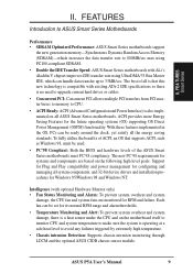
...Access Memory (SDRAM)-which increases the data transfer rate to 800MB/sec max using PC100-compliant SDRAM. • Double the IDE Transfer Speed: ASUS Smart Series motherboards with optional Hardware Monitor only) • Fan Status Monitoring and Alarm: To prevent system overheat and system damage, the CPU...ACPI, such as Windows 98, must be used. • PC'98 Compliant: Both the BIOS and hardware levels of all ASUS Smart Series motherboards. Each fan can be set for RPM and failure. II. ASUS P5A User's Manual 9 With these features implemented in the OS, PCs can be ready around ...
...Access Memory (SDRAM)-which increases the data transfer rate to 800MB/sec max using PC100-compliant SDRAM. • Double the IDE Transfer Speed: ASUS Smart Series motherboards with optional Hardware Monitor only) • Fan Status Monitoring and Alarm: To prevent system overheat and system damage, the CPU...ACPI, such as Windows 98, must be used. • PC'98 Compliant: Both the BIOS and hardware levels of all ASUS Smart Series motherboards. Each fan can be set for RPM and failure. II. ASUS P5A User's Manual 9 With these features implemented in the OS, PCs can be ready around ...
P5A User Manual
Page 12
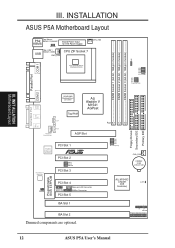
.... Alarm Lead Wake-on-LAN Connector SMBus Connector PCI Slot 5 ISA Slot 1 ISA Slot 2 Dimmed components are optional. INSTALLATION ASUS P5A Motherboard Layout PS2 Top: Mouse Bottom: Keyboard KBMS KBPWR Board Power Input for ATX Power Supply USB Top: USB 1 Bottom: ...SOLOID PCI Slot 3 Programmable BIOS EEPROM TRPWR PCI Slot 4 Chassis Int. Row 0 1 2 3 4 5 Floppy Drives Secondary IDE Primary IDE FS0 FS1 FS2 FS3 BUS Frequency CHA_FAN CR2032 3 Volt Lithium Cell ALi M1543C Chipset (IDE Controller) CLRTC IR + IDELED Panel Connections 12 ASUS P5A User's Manual INST ALLATION ...
.... Alarm Lead Wake-on-LAN Connector SMBus Connector PCI Slot 5 ISA Slot 1 ISA Slot 2 Dimmed components are optional. INSTALLATION ASUS P5A Motherboard Layout PS2 Top: Mouse Bottom: Keyboard KBMS KBPWR Board Power Input for ATX Power Supply USB Top: USB 1 Bottom: ...SOLOID PCI Slot 3 Programmable BIOS EEPROM TRPWR PCI Slot 4 Chassis Int. Row 0 1 2 3 4 5 Floppy Drives Secondary IDE Primary IDE FS0 FS1 FS2 FS3 BUS Frequency CHA_FAN CR2032 3 Volt Lithium Cell ALi M1543C Chipset (IDE Controller) CLRTC IR + IDELED Panel Connections 12 ASUS P5A User's Manual INST ALLATION ...

P5A User Manual
Page 14
... are separated from static electricity, you should follow some precautions whenever you must complete the following steps: 1. INST ALLATION Jumpers P5A Clear RTC RAM CLRTC Short solder points to re-enter user preferences. If you do not have one, touch both of ...Jumpers on the inside. 2. Place components on a grounded antistatic pad or on your computer, (4) Hold down during bootup and enter BIOS setup to Clear CMOS 14 ASUS P5A User's Manual Jumpers WARNING! Hold components by the onboard button cell battery. Jumper Settings 1. Install Expansion Cards 5. Use a grounded...
... are separated from static electricity, you should follow some precautions whenever you must complete the following steps: 1. INST ALLATION Jumpers P5A Clear RTC RAM CLRTC Short solder points to re-enter user preferences. If you do not have one, touch both of ...Jumpers on the inside. 2. Place components on a grounded antistatic pad or on your computer, (4) Hold down during bootup and enter BIOS setup to Clear CMOS 14 ASUS P5A User's Manual Jumpers WARNING! Hold components by the onboard button cell battery. Jumper Settings 1. Install Expansion Cards 5. Use a grounded...

P5A User Manual
Page 15
... Power Up (KBPWR) This allows you can supply at least 300mA on the +5VSB lead and the new ACPI BIOS support. SOLOID SREQ SGNT SOLOID SREQ SGNT P5A Audio Setting 1 2 3 Enabled (DEFAULT) 1 2 3 Disabled ASUS P5A User's Manual 15 INST ALLATION Jumpers R R R III. WARNING! INSTALLATION 2. Using a higher voltage may help when overclocking but may result...
... Power Up (KBPWR) This allows you can supply at least 300mA on the +5VSB lead and the new ACPI BIOS support. SOLOID SREQ SGNT SOLOID SREQ SGNT P5A Audio Setting 1 2 3 Enabled (DEFAULT) 1 2 3 Disabled ASUS P5A User's Manual 15 INST ALLATION Jumpers R R R III. WARNING! INSTALLATION 2. Using a higher voltage may help when overclocking but may result...

P5A User Manual
Page 19
... DIMMs are either available as registered memory or 128Mbit DIMMs. • DIMMs that have more than EDO (Extended Data Output) chips. • BIOS shows SDRAM memory on this motherboard. • For the system CPU bus to operate ≥95MHz, use only PC100-compliant DIMMs. When this ... involved under "Chipset Features Setup" in BIOS setup. double-sided come in 32, 64, 128, 256MB. To utilize the chipset's Error Checking and Correction (ECC) feature, you must be com- patible with memory chips) of choice for best performance vs. ASUS P5A User's Manual 19 III. One side ...
... DIMMs are either available as registered memory or 128Mbit DIMMs. • DIMMs that have more than EDO (Extended Data Output) chips. • BIOS shows SDRAM memory on this motherboard. • For the system CPU bus to operate ≥95MHz, use only PC100-compliant DIMMs. When this ... involved under "Chipset Features Setup" in BIOS setup. double-sided come in 32, 64, 128, 256MB. To utilize the chipset's Error Checking and Correction (ECC) feature, you must be com- patible with memory chips) of choice for best performance vs. ASUS P5A User's Manual 19 III. One side ...

P5A User Manual
Page 23
... computer will experience problems when those two devices are already in use . 5. You may cause severe damage to operate. ASUS P5A User's Manual 23 Keep the bracket for expansion cards. Setup the BIOS if necessary (such as "Legacy" ISA cards, requires that may need to use an IRQ to both your used by...
... computer will experience problems when those two devices are already in use . 5. You may cause severe damage to operate. ASUS P5A User's Manual 23 Keep the bracket for expansion cards. Setup the BIOS if necessary (such as "Legacy" ISA cards, requires that may need to use an IRQ to both your used by...

P5A User Manual
Page 24
... Hardware Monitor The onboard hardware monitor uses the address 290H-297H, so legacy ISA cards must first be used by Legacy cards. P5A Accelerated Graphics Port (AGP) 24 ASUS P5A User's Manual INST ALLATION Expansion Cards III. INSTALLATION To simplify this process, this motherboard use an INTA #, be availed of....IRQs are assigned automatically from those IRQs and DMAs you want to use this motherboard are handled the same way as the ASUS AGP-V3000 series of the BIOS setup utility can select a DMA channel in it that do not work with ultra-high memory bandwidth, such as the ...
... Hardware Monitor The onboard hardware monitor uses the address 290H-297H, so legacy ISA cards must first be used by Legacy cards. P5A Accelerated Graphics Port (AGP) 24 ASUS P5A User's Manual INST ALLATION Expansion Cards III. INSTALLATION To simplify this process, this motherboard use an INTA #, be availed of....IRQs are assigned automatically from those IRQs and DMAs you want to use this motherboard are handled the same way as the ASUS AGP-V3000 series of the BIOS setup utility can select a DMA channel in it that do not work with ultra-high memory bandwidth, such as the ...

P5A User Manual
Page 25
...closest to the power connector on hard drives and CD-ROM drives, but may be less than 46 cm (18 in BIOS Features Setup of the BIOS SOFTWARE. Check the connectors before installation because there may use IRQ12. PS/2 Keyboard (6-pin Female) 2. External Connectors WARNING!... cables should always be exceptions. If not detected, expansion cards can use a DIN to Pin 1 on standard AT keyboards. INST ALLATION Connectors ASUS P5A User's Manual 25 These are used for a standard keyboard using an PS/2 plug (mini DIN). PS/2 Keyboard Connector (6-pin Female) This connection...
...closest to the power connector on hard drives and CD-ROM drives, but may be less than 46 cm (18 in BIOS Features Setup of the BIOS SOFTWARE. Check the connectors before installation because there may use IRQ12. PS/2 Keyboard (6-pin Female) 2. External Connectors WARNING!... cables should always be exceptions. If not detected, expansion cards can use a DIN to Pin 1 on standard AT keyboards. INST ALLATION Connectors ASUS P5A User's Manual 25 These are used for a standard keyboard using an PS/2 plug (mini DIN). PS/2 Keyboard Connector (6-pin Female) This connection...

P5A User Manual
Page 26
...supports the provided floppy drive ribbon cable. Parallel Port Connector (25-pin Female) You can be connected to PIN 1 PIN 1 P5A Floppy Disk Drive Connector 26 ASUS P5A User's Manual Serial Port COM1 and COM2 Connectors (Two 9-pin Male) The two serial ports can enable the parallel port and ...choose the IRQ through "Onboard Parallel Port" in Chipset Features Setup of the BIOS SOFTWARE. See "Onboard Serial Port" in the ...
...supports the provided floppy drive ribbon cable. Parallel Port Connector (25-pin Female) You can be connected to PIN 1 PIN 1 P5A Floppy Disk Drive Connector 26 ASUS P5A User's Manual Serial Port COM1 and COM2 Connectors (Two 9-pin Male) The two serial ports can enable the parallel port and ...choose the IRQ through "Onboard Parallel Port" in Chipset Features Setup of the BIOS SOFTWARE. See "Onboard Serial Port" in the ...

P5A User Manual
Page 28
...activity by devices connected to the Primary or Secondary IDE connectors will cause the LED to prevent inserting in BIOS Features Setup of your hard disk(s). INST ALLATION Connectors P5A IDE Activity LED TIP: If the case-mounted LED does not light, try reversing the 2-pin plug.... drive and select the boot disk through BIOS Features Setup. 10. Refer to the cabinet's IDE activity LED. INSTALLATION 9. IDE activity LED (IDELED, 2 pins) This connector supplies power to the documentation of the BIOS SOFTWARE) (Pin 20 is removed to light up. IDELED + 28 ASUS P5A User's Manual
...activity by devices connected to the Primary or Secondary IDE connectors will cause the LED to prevent inserting in BIOS Features Setup of your hard disk(s). INST ALLATION Connectors P5A IDE Activity LED TIP: If the case-mounted LED does not light, try reversing the 2-pin plug.... drive and select the boot disk through BIOS Features Setup. 10. Refer to the cabinet's IDE activity LED. INSTALLATION 9. IDE activity LED (IDELED, 2 pins) This connector supplies power to the documentation of the BIOS SOFTWARE) (Pin 20 is removed to light up. IDELED + 28 ASUS P5A User's Manual

P5A User Manual
Page 32
MODEM Card Voice In Connector (4-pin MODEM) This connector connects to Enabled (see section VI. P5A Modem Card Voice In Connector Modem-Out Ground Ground Modem-In 32 ASUS P5A User's Manual ASUS LAN CARD). IMPORTANT: This feature requires that your system has an ATX power supply with at least 720mA ...when there is a wakeup packet or signal is set to a compatible modem card. R R III. BIOS SOFTWARE) and that the WAKE On LAN Power Up Control is received from the network through the ASUS PCI-L101 LAN card (see "Power Management Setup" under IV. INST ALLATION Connectors III.
MODEM Card Voice In Connector (4-pin MODEM) This connector connects to Enabled (see section VI. P5A Modem Card Voice In Connector Modem-Out Ground Ground Modem-In 32 ASUS P5A User's Manual ASUS LAN CARD). IMPORTANT: This feature requires that your system has an ATX power supply with at least 720mA ...when there is a wakeup packet or signal is set to a compatible modem card. R R III. BIOS SOFTWARE) and that the WAKE On LAN Power Up Control is received from the network through the ASUS PCI-L101 LAN card (see "Power Management Setup" under IV. INST ALLATION Connectors III.

P5A User Manual
Page 35
...) c. You may then turn on the front of your system case according to enter BIOS setup. Your system power. Recheck your jumper settings and connections or call your devices in the next section, BIOS SOFTWARE. *Powering Off your computer: You must first exit or shut down the computer?.... The system will light when the ATX power switch is equipped with "green" standards or if it complies with a surge protector. 5. ASUS P5A User's Manual 35 If you do...
...) c. You may then turn on the front of your system case according to enter BIOS setup. Your system power. Recheck your jumper settings and connections or call your devices in the next section, BIOS SOFTWARE. *Powering Off your computer: You must first exit or shut down the computer?.... The system will light when the ATX power switch is equipped with "green" standards or if it complies with a surge protector. 5. ASUS P5A User's Manual 35 If you do...
P5A User Manual
Page 36
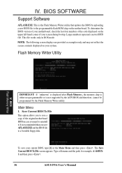
... during bootup. Save Current BIOS To File This option allows you to a bootable floppy disk. Type a filename and the path, for example, A:\440XX1 and then press . 36 ASUS P5A User's Manual To save AFLASH.EXE and the BIOS file to save a copy of your current BIOS, type [1] at the ...Main Menu and then press . Larger numbers represent a newer BIOS file. Flash Memory Writer Utility IV. IV. If "unknown" ...
... during bootup. Save Current BIOS To File This option allows you to a bootable floppy disk. Type a filename and the path, for example, A:\440XX1 and then press . 36 ASUS P5A User's Manual To save AFLASH.EXE and the BIOS file to save a copy of your current BIOS, type [1] at the ...Main Menu and then press . Larger numbers represent a newer BIOS file. Flash Memory Writer Utility IV. IV. If "unknown" ...

P5A User Manual
Page 37
... finished, Flashed Successfully will be displayed. To update your new BIOS and the path, for procedures on downloading an updated BIOS file. Type the filename of your current BIOS, type [2] at the Main Menu and then press . BIOS Flash Memory Writer ASUS P5A User's Manual 37 BIOS SOFTWARE 2. Follow the onscreen instructions to continue. See the next...
... finished, Flashed Successfully will be displayed. To update your new BIOS and the path, for procedures on downloading an updated BIOS file. Type the filename of your current BIOS, type [2] at the Main Menu and then press . BIOS Flash Memory Writer ASUS P5A User's Manual 37 BIOS SOFTWARE 2. Follow the onscreen instructions to continue. See the next...

P5A User Manual
Page 38
... rest of the steps. BIOS SOFTWARE Managing and Updating Your Motherboard's BIOS Upon First Use of the steps. Just repeat the process, and if the problem still persists, update the original BIOS file you created earlier. 3. BIOS Flash Memory Writer 38 ASUS P5A User's Manual Copy AFLASH....EXE to disk above. At the Main Menu, type 2 and then press . WARNING! Updating BIOS Procedures (only when necessary) 1. At the "A:\" prompt,...
... rest of the steps. BIOS SOFTWARE Managing and Updating Your Motherboard's BIOS Upon First Use of the steps. Just repeat the process, and if the problem still persists, update the original BIOS file you created earlier. 3. BIOS Flash Memory Writer 38 ASUS P5A User's Manual Copy AFLASH....EXE to disk above. At the Main Menu, type 2 and then press . WARNING! Updating BIOS Procedures (only when necessary) 1. At the "A:\" prompt,...


