P5A User Manual
Page 1
R P5A Pentium® Super7 Motherboard USER'S MANUAL
R P5A Pentium® Super7 Motherboard USER'S MANUAL
P5A User Manual
Page 2
... IMPLIED WARRANTIES OR CONDITIONS OF MERCHANTABILITY OR FITNESS FOR A PARTICULAR PURPOSE. Manual updates are released for each product design represented by any of the means indicated on the product itself. Product Name: ASUS P5A Manual Revision: 1.07 E382 Release Date: May 1999 2 ASUS P5A User's Manual Manual revisions are represented by the third digit in any form or by...
... IMPLIED WARRANTIES OR CONDITIONS OF MERCHANTABILITY OR FITNESS FOR A PARTICULAR PURPOSE. Manual updates are released for each product design represented by any of the means indicated on the product itself. Product Name: ASUS P5A Manual Revision: 1.07 E382 Release Date: May 1999 2 ASUS P5A User's Manual Manual revisions are represented by the third digit in any form or by...

P5A User Manual
Page 3
...-2-2894-3447 ext. 111 Fax: +886-2-2895-9254 Email: tsd@asus.com.tw Newsgroup: news2.asus.com.tw WWW: www.asus.com.tw FTP: ftp.asus.com.tw/pub/ASUS ASUS COMPUTER INTERNATIONAL (America) Marketing Address: 6737 Mowry Avenue, Mowry Business ...ASUS ASUS COMPUTER GmbH (Europe) Marketing Address: Harkort Str. 25, 40880 Ratingen, BRD, Germany Telephone: 49-2102-445011 Fax: 49-2102-442066 Email: [email protected] Technical Support Hotline: 49-2102-499712 BBS: 49-2102-448690 Email: [email protected] WWW: www.asuscom.de FTP: ftp.asuscom.de/pub/ASUSCOM ASUS P5A User's Manual...
...-2-2894-3447 ext. 111 Fax: +886-2-2895-9254 Email: tsd@asus.com.tw Newsgroup: news2.asus.com.tw WWW: www.asus.com.tw FTP: ftp.asus.com.tw/pub/ASUS ASUS COMPUTER INTERNATIONAL (America) Marketing Address: 6737 Mowry Avenue, Mowry Business ...ASUS ASUS COMPUTER GmbH (Europe) Marketing Address: Harkort Str. 25, 40880 Ratingen, BRD, Germany Telephone: 49-2102-445011 Fax: 49-2102-442066 Email: [email protected] Technical Support Hotline: 49-2102-499712 BBS: 49-2102-448690 Email: [email protected] WWW: www.asuscom.de FTP: ftp.asuscom.de/pub/ASUSCOM ASUS P5A User's Manual...

P5A User Manual
Page 4
...Setup 43 Chipset Features Setup 45 Details of Chipset Features Setup 46 Power Management Setup 49 Details of the ASUS P5A Motherboard 11 III. Jumpers 14 Jumper Settings 14 Compatible Cyrix CPU Identification 18 2. Expansion Cards 23 Expansion ... Menu 36 Managing and Updating Your Motherboard's BIOS 38 6. CONTENTS I. FEATURES 8 ASUS P5A Motherboard 8 Introduction to ASUS Smart Series Motherboards 9 Parts of Power Management Setup 49 4 ASUS P5A User's Manual External Connectors 25 Power Connection Procedures 35 Support Software 36 Flash Memory Writer Utility 36...
...Setup 43 Chipset Features Setup 45 Details of Chipset Features Setup 46 Power Management Setup 49 Details of the ASUS P5A Motherboard 11 III. Jumpers 14 Jumper Settings 14 Compatible Cyrix CPU Identification 18 2. Expansion Cards 23 Expansion ... Menu 36 Managing and Updating Your Motherboard's BIOS 38 6. CONTENTS I. FEATURES 8 ASUS P5A Motherboard 8 Introduction to ASUS Smart Series Motherboards 9 Parts of Power Management Setup 49 4 ASUS P5A User's Manual External Connectors 25 Power Connection Procedures 35 Support Software 36 Flash Memory Writer Utility 36...

P5A User Manual
Page 5
... Setup 57 Exit Without Saving 57 V. ASUS CIDB 63 The ASUS CIDB Chassis Sensor 63 Using the ASUS CIDB 63 Setting up the ASUS CIDB 64 ASUS CIDB Additional Considerations 64 VII. ASUS LAN Card 65 ASUS PCI-L101 Fast Ethernet Card 65 Features 66 Software Driver Support 66 Question and Answer 66 APPENDIX 67 Glossary 67 ASUS P5A User's Manual 5
... Setup 57 Exit Without Saving 57 V. ASUS CIDB 63 The ASUS CIDB Chassis Sensor 63 Using the ASUS CIDB 63 Setting up the ASUS CIDB 64 ASUS CIDB Additional Considerations 64 VII. ASUS LAN Card 65 ASUS PCI-L101 Fast Ethernet Card 65 Features 66 Software Driver Support 66 Question and Answer 66 APPENDIX 67 Glossary 67 ASUS P5A User's Manual 5

P5A User Manual
Page 6
..., may cause undesired operation. Cet appareil numérique de la classe B est conforme à la norme NMB-003 du Canada. 6 ASUS P5A User's Manual This Class B digital apparatus complies with FCC Rules Part 15. Canadian Department of Communications. This equipment generates, uses and can be determined by turning... the equipment off and on, the user is no guarantee that to Part 15 of the FCC Rules. These limits are designed to comply with the limits for radio noise...
..., may cause undesired operation. Cet appareil numérique de la classe B est conforme à la norme NMB-003 du Canada. 6 ASUS P5A User's Manual This Class B digital apparatus complies with FCC Rules Part 15. Canadian Department of Communications. This equipment generates, uses and can be determined by turning... the equipment off and on, the user is no guarantee that to Part 15 of the FCC Rules. These limits are designed to comply with the limits for radio noise...

P5A User Manual
Page 7
... Installation of spare jumpers (1) Support CD with drivers and utilities (1) User's Manual ASUS CIDB chassis sensor module (optional) ASUS IrDA-compliant infrared module (optional) ASUS PCI-L101 Wake-On-LAN 10/100 Ethernet Card (optional) ASUS P5A User's Manual 7 Introduction Manual information and checklist II. ASUS L101 Card Installation of the ASUS LAN card (optional) APPENDIX Glossary of Terms Item Checklist Please...
... Installation of spare jumpers (1) Support CD with drivers and utilities (1) User's Manual ASUS CIDB chassis sensor module (optional) ASUS IrDA-compliant infrared module (optional) ASUS PCI-L101 Wake-On-LAN 10/100 Ethernet Card (optional) ASUS P5A User's Manual 7 Introduction Manual information and checklist II. ASUS L101 Card Installation of the ASUS LAN card (optional) APPENDIX Glossary of Terms Item Checklist Please...

P5A User Manual
Page 8
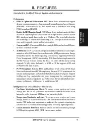
... DMI-enabled components.) (See section V) • USB, PS/2 Mouse, IrDA Connector: Supports an optional cable and bracket set . 8 ASUS P5A User's Manual These new SDRAMs are necessary to meet the enhanced 95MHz/100MHz bus speed requirement. • AGP Slot: Supports AGP cards for wireless connections....Trend ChipAwayVirus, and autodetection of either 5.25-inch (360KB or 1.2MB) or 3.5-inch (720KB, 1.44MB, or 2.88MB) disk drives. FEATURES ASUS P5A Motherboard • ALi AGPset: ALi® (Acer Laboratories Inc.) Aladdin V AGPset with support for a 100MHz Front Side Bus (FSB), Accelerated...
... DMI-enabled components.) (See section V) • USB, PS/2 Mouse, IrDA Connector: Supports an optional cable and bracket set . 8 ASUS P5A User's Manual These new SDRAMs are necessary to meet the enhanced 95MHz/100MHz bus speed requirement. • AGP Slot: Supports AGP cards for wireless connections....Trend ChipAwayVirus, and autodetection of either 5.25-inch (360KB or 1.2MB) or 3.5-inch (720KB, 1.44MB, or 2.88MB) disk drives. FEATURES ASUS P5A Motherboard • ALi AGPset: ALi® (Acer Laboratories Inc.) Aladdin V AGPset with support for a 100MHz Front Side Bus (FSB), Accelerated...
P5A User Manual
Page 9
...(SDRAM)-which increases the data transfer rate to 800MB/sec max using PC100-compliant SDRAM. • Double the IDE Transfer Speed: ASUS Smart Series motherboards with ALi's Aladdin V chipset improves IDE transfer rate using UltraDMA/33 Bus Master IDE, which can handle data ...32-bit device drivers and installation procedures for the future operating systems (OS) supporting OS Direct Power Management (OSPM) functionality. ASUS P5A User's Manual 9 The new PC'98 requirements for systems and components are monitored for configuring and managing all the energy saving standards. The best...
...(SDRAM)-which increases the data transfer rate to 800MB/sec max using PC100-compliant SDRAM. • Double the IDE Transfer Speed: ASUS Smart Series motherboards with ALi's Aladdin V chipset improves IDE transfer rate using UltraDMA/33 Bus Master IDE, which can handle data ...32-bit device drivers and installation procedures for the future operating systems (OS) supporting OS Direct Power Management (OSPM) functionality. ASUS P5A User's Manual 9 The new PC'98 requirements for systems and components are monitored for configuring and managing all the energy saving standards. The best...

P5A User Manual
Page 10
... Monitoring and Alert: System voltage levels are used up to critical motherboard components. This will warn the user before the system resources are monitored to ensure stable current to prevent possible application crashes. A simple glimpse... (requires ATX power supply): The system can determine the stage the computer is necessary to present enormous user interfaces and run large applications. This function reduces both energy consumption and system noise, and is an ...On (requires ATX power supply): This feature allows a computer to the user. 10 ASUS P5A User's Manual II.
... Monitoring and Alert: System voltage levels are used up to critical motherboard components. This will warn the user before the system resources are monitored to ensure stable current to prevent possible application crashes. A simple glimpse... (requires ATX power supply): The system can determine the stage the computer is necessary to present enormous user interfaces and run large applications. This function reduces both energy consumption and system noise, and is an ...On (requires ATX power supply): This feature allows a computer to the user. 10 ASUS P5A User's Manual II.

P5A User Manual
Page 11
II. FEA TURES Motherboard Parts II. FEATURES Parts of the ASUS P5A Motherboard PS/2 Mouse (top) and Keyboard USB Port ATX Power CPU ZIF ALi Aladdin V Socket 7 AGPset 3 DIMM Sockets Serial and Parallel Connectors 512KB/1MB Pipelined Burst L2 Cache Game/MIDI Port (optional) Accelerated Graphics Port ESS Audio (optional) 5 PCI Slots Health Monitoring Chip (optional) 2 ISA Slots ASUS P5A User's Manual 11
II. FEA TURES Motherboard Parts II. FEATURES Parts of the ASUS P5A Motherboard PS/2 Mouse (top) and Keyboard USB Port ATX Power CPU ZIF ALi Aladdin V Socket 7 AGPset 3 DIMM Sockets Serial and Parallel Connectors 512KB/1MB Pipelined Burst L2 Cache Game/MIDI Port (optional) Accelerated Graphics Port ESS Audio (optional) 5 PCI Slots Health Monitoring Chip (optional) 2 ISA Slots ASUS P5A User's Manual 11
P5A User Manual
Page 12
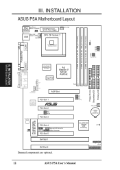
III. INSTALLATION ASUS P5A Motherboard Layout PS2 Top: Mouse Bottom: Keyboard KBMS KBPWR Board Power Input for ATX Power Supply USB Top: USB 1 Bottom: USB 2 PWR_FAN CPU ZIF Socket 7 ... IDE Primary IDE FS0 FS1 FS2 FS3 BUS Frequency CHA_FAN CR2032 3 Volt Lithium Cell ALi M1543C Chipset (IDE Controller) CLRTC IR + IDELED Panel Connections 12 ASUS P5A User's Manual
III. INSTALLATION ASUS P5A Motherboard Layout PS2 Top: Mouse Bottom: Keyboard KBMS KBPWR Board Power Input for ATX Power Supply USB Top: USB 1 Bottom: USB 2 PWR_FAN CPU ZIF Socket 7 ... IDE Primary IDE FS0 FS1 FS2 FS3 BUS Frequency CHA_FAN CR2032 3 Volt Lithium Cell ALi M1543C Chipset (IDE Controller) CLRTC IR + IDELED Panel Connections 12 ASUS P5A User's Manual
P5A User Manual
Page 13
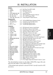
ASUS P5A User's Manual 13 INST ALLATION Contents III. INSTALLATION Jumpers 1) CLRTC p. 14 Real Time Clock (RTC) RAM 2) KBPWR p. 15 Keyboard Power Up 3) VIO1 p. 15 +3V Voltage Selection 4) SGNT,...
ASUS P5A User's Manual 13 INST ALLATION Contents III. INSTALLATION Jumpers 1) CLRTC p. 14 Real Time Clock (RTC) RAM 2) KBPWR p. 15 Keyboard Power Up 3) VIO1 p. 15 +3V Voltage Selection 4) SGNT,...

P5A User Manual
Page 14
...you do not have one, touch both of your computer, (4) Hold down during bootup and enter BIOS setup to Clear CMOS 14 ASUS P5A User's Manual Hold components by the onboard button cell battery. To clear the RTC data: (1) Turn off your computer, (2) Short solder points... 5. Jumpers WARNING! Unplug your computer. 1. III. Install the Central Processing Unit (CPU) 4. INST ALLATION Jumpers P5A Clear RTC RAM CLRTC Short solder points to re-enter user preferences. INSTALLATION Installation Steps Before using a small metalic object, (3) Turn on the inside. 2. Connect Ribbon Cables,...
...you do not have one, touch both of your computer, (4) Hold down during bootup and enter BIOS setup to Clear CMOS 14 ASUS P5A User's Manual Hold components by the onboard button cell battery. To clear the RTC data: (1) Turn off your computer, (2) Short solder points... 5. Jumpers WARNING! Unplug your computer. 1. III. Install the Central Processing Unit (CPU) 4. INST ALLATION Jumpers P5A Clear RTC RAM CLRTC Short solder points to re-enter user preferences. INSTALLATION Installation Steps Before using a small metalic object, (3) Turn on the inside. 2. Connect Ribbon Cables,...

P5A User Manual
Page 15
... supply at least 300mA on the +5VSB lead and the new ACPI BIOS support. SOLOID SREQ SGNT SOLOID SREQ SGNT P5A Audio Setting 1 2 3 Enabled (DEFAULT) 1 2 3 Disabled ASUS P5A User's Manual 15 INST ALLATION Jumpers R R R III. P5A Voltage Input/Output Selection 123 VIO1 3.5Volts (DEFAULT) 123 3.6Volts 4. Use default setting. Set to disable or enable the keyboard...
... supply at least 300mA on the +5VSB lead and the new ACPI BIOS support. SOLOID SREQ SGNT SOLOID SREQ SGNT P5A Audio Setting 1 2 3 Enabled (DEFAULT) 1 2 3 Disabled ASUS P5A User's Manual 15 INST ALLATION Jumpers R R R III. P5A Voltage Input/Output Selection 123 VIO1 3.5Volts (DEFAULT) 123 3.6Volts 4. Use default setting. Set to disable or enable the keyboard...

P5A User Manual
Page 16
... on the opposite page to BUS Frequency Multiple (BF0, BF1, BF2) These jumpers set in conjunction with your CPU when possible. 16 ASUS P5A User's Manual INST ALLATION Jumpers III. Frequencies above 100MHz exceed the specifications for the onboard chipset and are not guaranteed to be set the frequency ratio ... 77.6MHz 38.3MHz 120MHz 80MHz 40MHz CPU External Clock (BUS) Frequency Selection BF2 BF1 BF0 BF2 BF1 BF0 BF2 BF1 BF0 BF2 BF1 BF0 P5A Match the Mult. (Multiple) column of the CPU's External frequency (or BUS Clock). Always refer to the CPU, chipset, and AGP. R III...
... on the opposite page to BUS Frequency Multiple (BF0, BF1, BF2) These jumpers set in conjunction with your CPU when possible. 16 ASUS P5A User's Manual INST ALLATION Jumpers III. Frequencies above 100MHz exceed the specifications for the onboard chipset and are not guaranteed to be set the frequency ratio ... 77.6MHz 38.3MHz 120MHz 80MHz 40MHz CPU External Clock (BUS) Frequency Selection BF2 BF1 BF0 BF2 BF1 BF0 BF2 BF1 BF0 BF2 BF1 BF0 P5A Match the Mult. (Multiple) column of the CPU's External frequency (or BUS Clock). Always refer to the CPU, chipset, and AGP. R III...

P5A User Manual
Page 17
...the Internal speed of your CPU as follows: CPU Model Freq. (BUS Freq.) (Freq. NOTE: For updated processor settings, visit the ASUS web site (see next page). ASUS P5A User's Manual 17 III. FS3 FS2 FS1 FS0 BF0 BF1 BF2 AMD-K6-III/450 AMD-K6-III/400 450MHz A-4.5x 100MHz [2-3] [1-2] [1-2] [1-2] ...[----] IDT WinChip 2™ 240MHz F-4.0x 60MHz [2-3] [2-3] [2-3] [2-3] [2-3] [1-2] [2-3] *The only IBM or Cyrix 6x86(L) (or M I) that is supported on this motherboard is revision 2.7 or later (see ASUS CONTACT INFORMATION for URLs). BUS F. INST ALLATION Jumpers III. Mult.) Mult.
...the Internal speed of your CPU as follows: CPU Model Freq. (BUS Freq.) (Freq. NOTE: For updated processor settings, visit the ASUS web site (see next page). ASUS P5A User's Manual 17 III. FS3 FS2 FS1 FS0 BF0 BF1 BF2 AMD-K6-III/450 AMD-K6-III/400 450MHz A-4.5x 100MHz [2-3] [1-2] [1-2] [1-2] ...[----] IDT WinChip 2™ 240MHz F-4.0x 60MHz [2-3] [2-3] [2-3] [2-3] [2-3] [1-2] [2-3] *The only IBM or Cyrix 6x86(L) (or M I) that is supported on this motherboard is revision 2.7 or later (see ASUS CONTACT INFORMATION for URLs). BUS F. INST ALLATION Jumpers III. Mult.) Mult.

P5A User Manual
Page 18
... Core Voltage Selection 1 2 3 2.0Volts 2.1Volts 1 2 3 2.5Volts 2.6Volts 1 2 3 3.0Volts 3.1Volts 1 2 3 3.5Volts 2.2Volts 2.7Volts 3.2Volts 2.3Volts 2.8Volts 3.3Volts 2.4Volts 2.9Volts 3.4Volts 18 ASUS P5A User's Manual Manufacturer CPU Type AMD (.25micron) K6-III/400,450 K6-2/450,475 Single Plane ---- III. Intel P55C-MMX ---- Because CPU designs change rapidly, the table ...
... Core Voltage Selection 1 2 3 2.0Volts 2.1Volts 1 2 3 2.5Volts 2.6Volts 1 2 3 3.0Volts 3.1Volts 1 2 3 3.5Volts 2.2Volts 2.7Volts 3.2Volts 2.3Volts 2.8Volts 3.3Volts 2.4Volts 2.9Volts 3.4Volts 18 ASUS P5A User's Manual Manufacturer CPU Type AMD (.25micron) K6-III/400,450 K6-2/450,475 Single Plane ---- III. Intel P55C-MMX ---- Because CPU designs change rapidly, the table ...

P5A User Manual
Page 19
... 3 (Rows 4&5) SDRAM 8, 16, 32, 64, 128, 256MB x1 Total System Memory (Max 768MB) = NOTES • At the time this User's Manual was written, 256MB DIMMs are used must use only PC100-compliant DIMMs. When this motherboard operates at ≥95MHz, most system will not even boot..., 128, 256MB. Memory speed setup is the memory of the strict timing issues involved under "Chipset Features Setup" in BIOS setup. ASUS P5A User's Manual 19 If your DIMMs are generally thinner with the current Intel PC100 SDRAM specification.. double-sided come in BIOS setup. stability. •...
... 3 (Rows 4&5) SDRAM 8, 16, 32, 64, 128, 256MB x1 Total System Memory (Max 768MB) = NOTES • At the time this User's Manual was written, 256MB DIMMs are used must use only PC100-compliant DIMMs. When this motherboard operates at ≥95MHz, most system will not even boot..., 128, 256MB. Memory speed setup is the memory of the strict timing issues involved under "Chipset Features Setup" in BIOS setup. ASUS P5A User's Manual 19 If your DIMMs are generally thinner with the current Intel PC100 SDRAM specification.. double-sided come in BIOS setup. stability. •...

P5A User Manual
Page 20
... Pin DIMM Memory Sockets The DIMMs must tell your retailer the correct DIMM type before purchasing. III. This motherboard supports four clock signals. 20 ASUS P5A User's Manual SDRAM DIMMs have different pin contacts on each side and therefore have the same pin contacts on the motherboard. INSTALLATION DIMM Memory Installation Procedures: Insert ...
... Pin DIMM Memory Sockets The DIMMs must tell your retailer the correct DIMM type before purchasing. III. This motherboard supports four clock signals. 20 ASUS P5A User's Manual SDRAM DIMMs have different pin contacts on each side and therefore have the same pin contacts on the motherboard. INSTALLATION DIMM Memory Installation Procedures: Insert ...

