
P5A-B User Manual
Page 1
R P5A-B Pentium® Super7 Motherboard USER'S MANUAL
R P5A-B Pentium® Super7 Motherboard USER'S MANUAL

P5A-B User Manual
Page 2
... RESPONSIBILITY OR LIABILITY FOR ANY ERRORS OR INACCURACIES THAT MAY APPEAR IN THIS MANUAL, INCLUDING THE PRODUCTS AND SOFTWARE DESCRIBED IN IT. Product Name: ASUS P5A-B Manual Revision: 1.07 E381 Release Date: April 1999 2 ASUS P5A-B User's Manual USER'S NOTICE No part of this manual may or may be reproduced, transmitted, transcribed, stored in a retrieval system, or translated...
... RESPONSIBILITY OR LIABILITY FOR ANY ERRORS OR INACCURACIES THAT MAY APPEAR IN THIS MANUAL, INCLUDING THE PRODUCTS AND SOFTWARE DESCRIBED IN IT. Product Name: ASUS P5A-B Manual Revision: 1.07 E381 Release Date: April 1999 2 ASUS P5A-B User's Manual USER'S NOTICE No part of this manual may or may be reproduced, transmitted, transcribed, stored in a retrieval system, or translated...
P5A-B User Manual
Page 3
...-2-2894-3447 ext. 111 Fax: +886-2-2895-9254 Email: tsd@asus.com.tw Newsgroup: news2.asus.com.tw WWW: www.asus.com.tw FTP: ftp.asus.com.tw/pub/ASUS ASUS COMPUTER INTERNATIONAL (America) Marketing Address: 6737 Mowry Avenue, Mowry Business ...ASUS ASUS COMPUTER GmbH (Europe) Marketing Address: Harkort Str. 25, 40880 Ratingen, BRD, Germany Telephone: 49-2102-445011 Fax: 49-2102-442066 Email: [email protected] Technical Support Hotline: 49-2102-499712 BBS: 49-2102-448690 Email: [email protected] WWW: www.asuscom.de FTP: ftp.asuscom.de/pub/ASUSCOM ASUS P5A-B User's Manual...
...-2-2894-3447 ext. 111 Fax: +886-2-2895-9254 Email: tsd@asus.com.tw Newsgroup: news2.asus.com.tw WWW: www.asus.com.tw FTP: ftp.asus.com.tw/pub/ASUS ASUS COMPUTER INTERNATIONAL (America) Marketing Address: 6737 Mowry Avenue, Mowry Business ...ASUS ASUS COMPUTER GmbH (Europe) Marketing Address: Harkort Str. 25, 40880 Ratingen, BRD, Germany Telephone: 49-2102-445011 Fax: 49-2102-442066 Email: [email protected] Technical Support Hotline: 49-2102-499712 BBS: 49-2102-448690 Email: [email protected] WWW: www.asuscom.de FTP: ftp.asuscom.de/pub/ASUSCOM ASUS P5A-B User's Manual...

P5A-B User Manual
Page 4
... Accelerated Graphics Port 24 5. INTRODUCTION 7 How this Manual is Organized 7 Item Checklist 7 II. External Connectors 25 Power Connection Procedures 35 IV. BIOS SOFTWARE 36 Flash Memory Writer Utility 36 Main Menu 36 Managing and Updating Your Motherboard's BIOS 38 6. FEATURES 8 ASUS P5A-B Motherboard 8 Introduction to ASUS Smart Series Motherboards 9 Parts of PNP and PCI...
... Accelerated Graphics Port 24 5. INTRODUCTION 7 How this Manual is Organized 7 Item Checklist 7 II. External Connectors 25 Power Connection Procedures 35 IV. BIOS SOFTWARE 36 Flash Memory Writer Utility 36 Main Menu 36 Managing and Updating Your Motherboard's BIOS 38 6. FEATURES 8 ASUS P5A-B Motherboard 8 Introduction to ASUS Smart Series Motherboards 9 Parts of PNP and PCI...

P5A-B User Manual
Page 5
...Save & Exit Setup 57 Exit Without Saving 57 V. ASUS CIDB 63 The ASUS CIDB Chassis Sensor 63 Using the ASUS CIDB 63 Setting up the ASUS CIDB 64 ASUS CIDB Additional Considerations 64 VII. SUPPORT SOFTWARE 59 ASUS Smart Motherboard Support CD 59 Desktop Management Interface (DMI...the ASUS DMI Configuration Utility 60 Starting the ASUS DMI Configuration Utility 60 Using the ASUS DMI Configuration Utility 61 VI. ASUS LAN Card 65 ASUS PCI-L101 Fast Ethernet Card 65 Features 66 Software Driver Support 66 Question and Answer 66 APPENDIX 67 Glossary 67 ASUS P5A-B User's Manual 5...
...Save & Exit Setup 57 Exit Without Saving 57 V. ASUS CIDB 63 The ASUS CIDB Chassis Sensor 63 Using the ASUS CIDB 63 Setting up the ASUS CIDB 64 ASUS CIDB Additional Considerations 64 VII. SUPPORT SOFTWARE 59 ASUS Smart Motherboard Support CD 59 Desktop Management Interface (DMI...the ASUS DMI Configuration Utility 60 Starting the ASUS DMI Configuration Utility 60 Using the ASUS DMI Configuration Utility 61 VI. ASUS LAN Card 65 ASUS PCI-L101 Fast Ethernet Card 65 Features 66 Software Driver Support 66 Question and Answer 66 APPENDIX 67 Glossary 67 ASUS P5A-B User's Manual 5...

P5A-B User Manual
Page 6
... cause harmful interference, and • This device must accept any interference received, including interference that may cause harmful interference to Part 15 of Communications. 6 ASUS P5A-B User's Manual FCC & DOC COMPLIANCE Federal Communications Commission Statement This device complies with FCC regulations. This equipment has been tested and found to assure compliance with FCC...
... cause harmful interference, and • This device must accept any interference received, including interference that may cause harmful interference to Part 15 of Communications. 6 ASUS P5A-B User's Manual FCC & DOC COMPLIANCE Federal Communications Commission Statement This device complies with FCC regulations. This equipment has been tested and found to assure compliance with FCC...

P5A-B User Manual
Page 7
...and (2) 3.5" floppy disk drives (1) Bag of the ASUS CIDB Chassis Sensor (optional) VII. ASUS CIDB Installation of spare jumpers (1) CD disc with support drivers and utilities (1) User's Manual Audio Bracket (only available with ISA audio option) ASUS CIDB chassis sensor module (optional) PS/2 Mouse, Infrared..., USB1, and USB2 external connector module (optional) ASUS PCI-L101 Wake-On-LAN 10/100 Ethernet Card (optional) ASUS P5A-B User's Manual 7 Support Software Information on the included support software VI. If you discover damaged or missing...
...and (2) 3.5" floppy disk drives (1) Bag of the ASUS CIDB Chassis Sensor (optional) VII. ASUS CIDB Installation of spare jumpers (1) CD disc with support drivers and utilities (1) User's Manual Audio Bracket (only available with ISA audio option) ASUS CIDB chassis sensor module (optional) PS/2 Mouse, Infrared..., USB1, and USB2 external connector module (optional) ASUS PCI-L101 Wake-On-LAN 10/100 Ethernet Card (optional) ASUS P5A-B User's Manual 7 Support Software Information on the included support software VI. If you discover damaged or missing...

P5A-B User Manual
Page 8
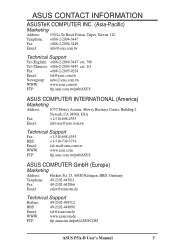
...Requires DMI-enabled components.) (See section V) • USB, PS/2 Mouse, IrDA Connector: Supports an optional cable and bracket set . 8 ASUS P5A-B User's Manual II. A second IrDA connector is available for high performance, component level interconnection targeted at 3D graphical display applications. • ISA Audio (optional... with three DIMM sockets to support Intel PC100-compliant SDRAMs (8, 16, 32, 64, 128, or 256MB) up to 768MB. FEATURES ASUS P5A-B Motherboard • ALi AGPset: ALi® (Acer Laboratories Inc.) Aladdin V AGPset with support for a 100MHz Front Side Bus (FSB...
...Requires DMI-enabled components.) (See section V) • USB, PS/2 Mouse, IrDA Connector: Supports an optional cable and bracket set . 8 ASUS P5A-B User's Manual II. A second IrDA connector is available for high performance, component level interconnection targeted at 3D graphical display applications. • ISA Audio (optional... with three DIMM sockets to support Intel PC100-compliant SDRAMs (8, 16, 32, 64, 128, or 256MB) up to 768MB. FEATURES ASUS P5A-B Motherboard • ALi AGPset: ALi® (Acer Laboratories Inc.) Aladdin V AGPset with support for a 100MHz Front Side Bus (FSB...
P5A-B User Manual
Page 9
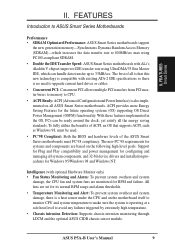
...) is operating at a safe heat level to 800MB/sec max using PC100-compliant SDRAM. • Double the IDE Transfer Speed: ASUS Smart Series motherboards with optional Hardware Monitor only) • Fan Status Monitoring and Alarm: To prevent system overheat and system damage, the... all ASUS Smart Series motherboards. Intelligence (with ALi's Aladdin V chipset improves IDE transfer rate using UltraDMA/33 Bus Master IDE, which can be used. • PC'98 Compliant: Both the BIOS and hardware levels of the ASUS Smart Series motherboards meet PC'98 compliancy. ASUS P5A-B User's Manual 9...
...) is operating at a safe heat level to 800MB/sec max using PC100-compliant SDRAM. • Double the IDE Transfer Speed: ASUS Smart Series motherboards with optional Hardware Monitor only) • Fan Status Monitoring and Alarm: To prevent system overheat and system damage, the... all ASUS Smart Series motherboards. Intelligence (with ALi's Aladdin V chipset improves IDE transfer rate using UltraDMA/33 Bus Master IDE, which can be used. • PC'98 Compliant: Both the BIOS and hardware levels of the ASUS Smart Series motherboards meet PC'98 compliancy. ASUS P5A-B User's Manual 9...
P5A-B User Manual
Page 10
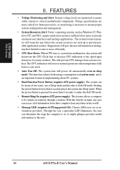
... Alert: Today's operating systems, such as information providers. II. Suggestions will deactivate the CPU Clock line to decrease CPU utilization to the user. 10 ASUS P5A-B User's Manual FEA TURES P5A-B Series II. Voltage specifications are more than 4 seconds places the system into Sleep mode. When the power button is in the world! •...
... Alert: Today's operating systems, such as information providers. II. Suggestions will deactivate the CPU Clock line to decrease CPU utilization to the user. 10 ASUS P5A-B User's Manual FEA TURES P5A-B Series II. Voltage specifications are more than 4 seconds places the system into Sleep mode. When the power button is in the world! •...
P5A-B User Manual
Page 11
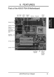
II. FEA TURES Motherboard Parts II. FEATURES Parts of the ASUS P5A-B Motherboard Serial Parallel 3 DIMM ALi Aladdin V Ports Port Sockets AGPset ATX Power AT Connector CPU ZIF Socket 7 Keyboard USB/MIR Floppy/IDE Connectors 512KB/1024KB Pipelined Burst L2 Cache Accelerated Graphics Port 3 PCI Slots 2 ISA Slots Programmable Flash ROM IrDA C-Media 3D Positional Sound Chip (optional) ASUS P5A-B User's Manual 11
II. FEA TURES Motherboard Parts II. FEATURES Parts of the ASUS P5A-B Motherboard Serial Parallel 3 DIMM ALi Aladdin V Ports Port Sockets AGPset ATX Power AT Connector CPU ZIF Socket 7 Keyboard USB/MIR Floppy/IDE Connectors 512KB/1024KB Pipelined Burst L2 Cache Accelerated Graphics Port 3 PCI Slots 2 ISA Slots Programmable Flash ROM IrDA C-Media 3D Positional Sound Chip (optional) ASUS P5A-B User's Manual 11
P5A-B User Manual
Page 12
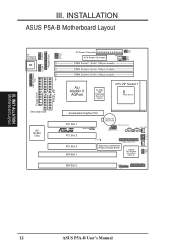
INST ALLATION Motherboard Layout 12 ASUS P5A-B User's Manual INSTALLATION ASUS P5A-B Motherboard Layout AT Keyboard Connector KB USB, PS/2 Mouse, IrDA COM 1 COM 2 Parallel Port Row 5 4 3 2 1 0 VIO1 AT Power Connector VIO0 FS3 FS2 PWR_FAN FS1 FS0 ...
INST ALLATION Motherboard Layout 12 ASUS P5A-B User's Manual INSTALLATION ASUS P5A-B Motherboard Layout AT Keyboard Connector KB USB, PS/2 Mouse, IrDA COM 1 COM 2 Parallel Port Row 5 4 3 2 1 0 VIO1 AT Power Connector VIO0 FS3 FS2 PWR_FAN FS1 FS0 ...

P5A-B User Manual
Page 13
III. ASUS P5A-B User's Manual 13 INSTALLATION Jumpers 1) CLRTC p. 15 Real Time Clock (RTC) RAM 2) VIO p. 15 Voltage Input/Output Selection 4) FS0, FS1, FS2, FS3 p. 16 CPU External (BUS) Frequency ...
III. ASUS P5A-B User's Manual 13 INSTALLATION Jumpers 1) CLRTC p. 15 Real Time Clock (RTC) RAM 2) VIO p. 15 Voltage Input/Output Selection 4) FS0, FS1, FS2, FS3 p. 16 CPU External (BUS) Frequency ...
P5A-B User Manual
Page 14
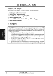
... the edges and try not to a metal object, such as SCSI cards, contain very delicate Integrated Circuit (IC) chips. III. INST ALLATION Jumpers 14 ASUS P5A-B User's Manual Set Jumpers on the bag that came with the component whenever the components are separated from static electricity, you should follow some precautions whenever you...
... the edges and try not to a metal object, such as SCSI cards, contain very delicate Integrated Circuit (IC) chips. III. INST ALLATION Jumpers 14 ASUS P5A-B User's Manual Set Jumpers on the bag that came with the component whenever the components are separated from static electricity, you should follow some precautions whenever you...

P5A-B User Manual
Page 15
INST ALLATION Jumpers III. R P5A-B Clear RTC RAM CLRTC Short solder points to the DRAM, chipset, and AGP. Voltage Input/Output Selection (VIO) This jumper allows you to select the ... VIO0 VIO1 III. Real Time Clock (RTC) RAM (CLRTC) The CMOS RAM is powered by the onboard button cell battery. R 1 2 3 3.5Volts 3.6Volts 3.8Volts (DEFAULT) 4.0Volts P5A-B Voltage Input/Output Selection WARNING! ASUS P5A-B User's Manual 15 INSTALLATION Jumper Settings 1.
INST ALLATION Jumpers III. R P5A-B Clear RTC RAM CLRTC Short solder points to the DRAM, chipset, and AGP. Voltage Input/Output Selection (VIO) This jumper allows you to select the ... VIO0 VIO1 III. Real Time Clock (RTC) RAM (CLRTC) The CMOS RAM is powered by the onboard button cell battery. R 1 2 3 3.5Volts 3.6Volts 3.8Volts (DEFAULT) 4.0Volts P5A-B Voltage Input/Output Selection WARNING! ASUS P5A-B User's Manual 15 INSTALLATION Jumper Settings 1.

P5A-B User Manual
Page 16
... BF2 BF1 BF0 BF2 BF1 BF0 P5A-B Match the Mult. (Multiple) column of the table on the following page is for CPU External (BUS) Frequency Selection. CPU to BUS Frequency Multiple (BF0, BF1, BF2) These jumpers set in conjunction with your CPU when possible. 16 ASUS P5A-B User's Manual CPU D → - INSTALLATION 3. INST ALLATION...
... BF2 BF1 BF0 BF2 BF1 BF0 P5A-B Match the Mult. (Multiple) column of the table on the following page is for CPU External (BUS) Frequency Selection. CPU to BUS Frequency Multiple (BF0, BF1, BF2) These jumpers set in conjunction with your CPU when possible. 16 ASUS P5A-B User's Manual CPU D → - INSTALLATION 3. INST ALLATION...

P5A-B User Manual
Page 17
... 200MHz IBM/Cyrix6x86MX-PR200 166MHz IBM/Cyrix 6x86MX-PR166 150MHz *IBM/Cyrix 6x86-PR166+ 133MHz *IBM/Cyrix 6x86L-PR166+ 133MHz IDT WinChip 2™ 240MHz Mult. ASUS P5A-B User's Manual 17
... 200MHz IBM/Cyrix6x86MX-PR200 166MHz IBM/Cyrix 6x86MX-PR166 150MHz *IBM/Cyrix 6x86-PR166+ 133MHz *IBM/Cyrix 6x86L-PR166+ 133MHz IDT WinChip 2™ 240MHz Mult. ASUS P5A-B User's Manual 17
P5A-B User Manual
Page 18
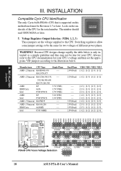
... VID1 VID2 VID3 VID0 VID1 VID2 VID3 VID0 VID1 VID2 VID3 1 2 3 2.0Volts 2.1Volts 1 2 3 2.5Volts 2.6Volts 1 2 3 3.0Volts 3.1Volts P5A-B CPU Vcore Voltage Selection 1 2 3 3.5Volts 2.2Volts 2.7Volts 3.2Volts 2.3Volts 2.8Volts 3.3Volts 2.4Volts 2.9Volts 3.4Volts 18 ASUS P5A-B User's Manual Look on this motherboard must be Revision 2.7 or later. III. INSTALLATION Compatible Cyrix CPU Identification The only...
... VID1 VID2 VID3 VID0 VID1 VID2 VID3 VID0 VID1 VID2 VID3 1 2 3 2.0Volts 2.1Volts 1 2 3 2.5Volts 2.6Volts 1 2 3 3.0Volts 3.1Volts P5A-B CPU Vcore Voltage Selection 1 2 3 3.5Volts 2.2Volts 2.7Volts 3.2Volts 2.3Volts 2.8Volts 3.3Volts 2.4Volts 2.9Volts 3.4Volts 18 ASUS P5A-B User's Manual Look on this motherboard must be Revision 2.7 or later. III. INSTALLATION Compatible Cyrix CPU Identification The only...
P5A-B User Manual
Page 19
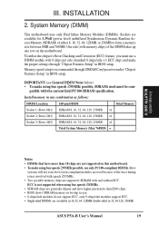
... Inline Memory Modules (DIMMs). patible with memory chips) of either 8, 16, 32, 64, 128MB, or 256MB to form a memory size between 8MB and 768MB. ASUS P5A-B User's Manual 19 To utilize the chipset's Error Checking and Correction (ECC) feature, you must be com- Memory speed setup is not supported when using bus speeds...
... Inline Memory Modules (DIMMs). patible with memory chips) of either 8, 16, 32, 64, 128MB, or 256MB to form a memory size between 8MB and 768MB. ASUS P5A-B User's Manual 19 To utilize the chipset's Error Checking and Correction (ECC) feature, you must be com- Memory speed setup is not supported when using bus speeds...
P5A-B User Manual
Page 20
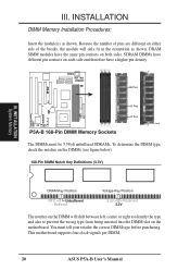
...on the DIMM will only fit in the orientation as shown. DRAM SIMM modules have a higher pin density. 88 Pins 60 Pins 20 Pins Lock P5A-B 168-Pin DIMM Memory Sockets The DIMMs must tell your retailer the correct DIMM type before purchasing. You must be 3.3Volt unbuffered SDRAMs. To ... on the DIMMs (see figure below). 168-Pin DIMM Notch Key Definitions (3.3V) R III. This motherboard supports four clock signals per DIMM. 20 ASUS P5A-B User's Manual Because the number of the breaks, the module will shift between left, center, or right to identify the type and also to prevent the wrong...
...on the DIMM will only fit in the orientation as shown. DRAM SIMM modules have a higher pin density. 88 Pins 60 Pins 20 Pins Lock P5A-B 168-Pin DIMM Memory Sockets The DIMMs must tell your retailer the correct DIMM type before purchasing. You must be 3.3Volt unbuffered SDRAMs. To ... on the DIMMs (see figure below). 168-Pin DIMM Notch Key Definitions (3.3V) R III. This motherboard supports four clock signals per DIMM. 20 ASUS P5A-B User's Manual Because the number of the breaks, the module will shift between left, center, or right to identify the type and also to prevent the wrong...


