
P5A-B User Manual
Page 1
R P5A-B Pentium® Super7 Motherboard USER'S MANUAL
R P5A-B Pentium® Super7 Motherboard USER'S MANUAL

P5A-B User Manual
Page 4
... Connectors 25 Power Connection Procedures 35 IV. System Memory (DIMM 19 DIMM Memory Installation Procedures 20 3. FEATURES 8 ASUS P5A-B Motherboard 8 Introduction to ASUS Smart Series Motherboards 9 Parts of PNP and PCI Setup 52 4 ASUS P5A-B User's Manual INTRODUCTION 7 How this Manual is Organized 7 Item Checklist 7 II. BIOS SOFTWARE 36 Flash Memory Writer Utility 36 Main Menu 36 Managing and...
... Connectors 25 Power Connection Procedures 35 IV. System Memory (DIMM 19 DIMM Memory Installation Procedures 20 3. FEATURES 8 ASUS P5A-B Motherboard 8 Introduction to ASUS Smart Series Motherboards 9 Parts of PNP and PCI Setup 52 4 ASUS P5A-B User's Manual INTRODUCTION 7 How this Manual is Organized 7 Item Checklist 7 II. BIOS SOFTWARE 36 Flash Memory Writer Utility 36 Main Menu 36 Managing and...

P5A-B User Manual
Page 5
SUPPORT SOFTWARE 59 ASUS Smart Motherboard Support CD 59 Desktop Management Interface (DMI 60 Introducing the ASUS DMI Configuration Utility 60 Starting the ASUS DMI Configuration Utility 60 Using the ASUS DMI Configuration Utility 61 VI. CONTENTS Load BIOS Defaults 54 ...ASUS CIDB 63 The ASUS CIDB Chassis Sensor 63 Using the ASUS CIDB 63 Setting up the ASUS CIDB 64 ASUS CIDB Additional Considerations 64 VII. ASUS LAN Card 65 ASUS PCI-L101 Fast Ethernet Card 65 Features 66 Software Driver Support 66 Question and Answer 66 APPENDIX 67 Glossary 67 ASUS P5A-B User's Manual...
SUPPORT SOFTWARE 59 ASUS Smart Motherboard Support CD 59 Desktop Management Interface (DMI 60 Introducing the ASUS DMI Configuration Utility 60 Starting the ASUS DMI Configuration Utility 60 Using the ASUS DMI Configuration Utility 61 VI. CONTENTS Load BIOS Defaults 54 ...ASUS CIDB 63 The ASUS CIDB Chassis Sensor 63 Using the ASUS CIDB 63 Setting up the ASUS CIDB 64 ASUS CIDB Additional Considerations 64 VII. ASUS LAN Card 65 ASUS PCI-L101 Fast Ethernet Card 65 Features 66 Software Driver Support 66 Question and Answer 66 APPENDIX 67 Glossary 67 ASUS P5A-B User's Manual...

P5A-B User Manual
Page 7
...motherboard IV. Introduction Manual information and checklist II. BIOS Software Instructions on setting up the BIOS software V. INTRODUCTION Sections/Checklist I . ASUS L101 Card Installation of the ASUS LAN card (optional) APPENDIX Glossary of Terms Item Checklist Check that your retailer. (1) ASUS Motherboard...'s Manual Audio Bracket (only available with ISA audio option) ASUS CIDB chassis sensor module (optional) PS/2 Mouse, Infrared, USB1, and USB2 external connector module (optional) ASUS PCI-L101 Wake-On-LAN 10/100 Ethernet Card (optional) ASUS P5A-B User's Manual 7...
...motherboard IV. Introduction Manual information and checklist II. BIOS Software Instructions on setting up the BIOS software V. INTRODUCTION Sections/Checklist I . ASUS L101 Card Installation of the ASUS LAN card (optional) APPENDIX Glossary of Terms Item Checklist Check that your retailer. (1) ASUS Motherboard...'s Manual Audio Bracket (only available with ISA audio option) ASUS CIDB chassis sensor module (optional) PS/2 Mouse, Infrared, USB1, and USB2 external connector module (optional) ASUS PCI-L101 Wake-On-LAN 10/100 Ethernet Card (optional) ASUS P5A-B User's Manual 7...

P5A-B User Manual
Page 8
...compatibility. (Requires DMI-enabled components.) (See section V) • USB, PS/2 Mouse, IrDA Connector: Supports an optional cable and bracket set . 8 ASUS P5A-B User's Manual Supports Japanese "Floppy 3 mode" (3.5-inch disk drive: 1.2MB) and LS-120 floppy disk drives (3.5-inch disk drive: 120 MB, 1.44MB, 720K... also be directed from COM2 to monitor your system's vital components/activities, such as Tape Backup and CD-ROM drives. II. FEATURES ASUS P5A-B Motherboard • ALi AGPset: ALi® (Acer Laboratories Inc.) Aladdin V AGPset with support for a 100MHz Front Side Bus (FSB), ...
...compatibility. (Requires DMI-enabled components.) (See section V) • USB, PS/2 Mouse, IrDA Connector: Supports an optional cable and bracket set . 8 ASUS P5A-B User's Manual Supports Japanese "Floppy 3 mode" (3.5-inch disk drive: 1.2MB) and LS-120 floppy disk drives (3.5-inch disk drive: 120 MB, 1.44MB, 720K... also be directed from COM2 to monitor your system's vital components/activities, such as Tape Backup and CD-ROM drives. II. FEATURES ASUS P5A-B Motherboard • ALi AGPset: ALi® (Acer Laboratories Inc.) Aladdin V AGPset with support for a 100MHz Front Side Bus (FSB), ...
P5A-B User Manual
Page 9
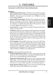
... multiple PCI transfers from PCI master buses to memory to 33MB/sec. FEATURES Introduction to ASUS Smart Series Motherboards Performance • SDRAM Optimized Performance: ASUS Smart Series motherboards support the new generation memory-Synchronous Dynamic Random Access Memory (SDRAM)-which can be used....ASUS P5A-B User's Manual 9 Intelligence (with ALi's Aladdin V chipset improves IDE transfer rate using UltraDMA/33 Bus Master IDE, which increases the data transfer rate to 800MB/sec max using PC100-compliant SDRAM. • Double the IDE Transfer Speed: ASUS Smart Series motherboards...
... multiple PCI transfers from PCI master buses to memory to 33MB/sec. FEATURES Introduction to ASUS Smart Series Motherboards Performance • SDRAM Optimized Performance: ASUS Smart Series motherboards support the new generation memory-Synchronous Dynamic Random Access Memory (SDRAM)-which can be used....ASUS P5A-B User's Manual 9 Intelligence (with ALi's Aladdin V chipset improves IDE transfer rate using UltraDMA/33 Bus Master IDE, which increases the data transfer rate to 800MB/sec max using PC100-compliant SDRAM. • Double the IDE Transfer Speed: ASUS Smart Series motherboards...
P5A-B User Manual
Page 10
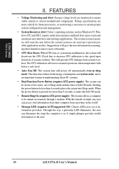
FEA TURES P5A-B Series II. The system resource monitor will prevent CPU damage from anywhere in sleep mode. This will warn... computer to the speed upon detection of two states, one is Sleep mode and the other is necessary to the user. 10 ASUS P5A-B User's Manual With this benefit on managing their computer from system overheat. A simple glimpse provides useful information to ensure proper system configuration and management....; Voltage Monitoring and Alert: System voltage levels are more critical for more memory and hard drive space to critical motherboard components.
FEA TURES P5A-B Series II. The system resource monitor will prevent CPU damage from anywhere in sleep mode. This will warn... computer to the speed upon detection of two states, one is Sleep mode and the other is necessary to the user. 10 ASUS P5A-B User's Manual With this benefit on managing their computer from system overheat. A simple glimpse provides useful information to ensure proper system configuration and management....; Voltage Monitoring and Alert: System voltage levels are more critical for more memory and hard drive space to critical motherboard components.
P5A-B User Manual
Page 11
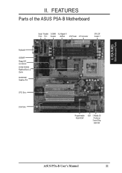
FEA TURES Motherboard Parts II. II. FEATURES Parts of the ASUS P5A-B Motherboard Serial Parallel 3 DIMM ALi Aladdin V Ports Port Sockets AGPset ATX Power AT Connector CPU ZIF Socket 7 Keyboard USB/MIR Floppy/IDE Connectors 512KB/1024KB Pipelined Burst L2 Cache Accelerated Graphics Port 3 PCI Slots 2 ISA Slots Programmable Flash ROM IrDA C-Media 3D Positional Sound Chip (optional) ASUS P5A-B User's Manual 11
FEA TURES Motherboard Parts II. II. FEATURES Parts of the ASUS P5A-B Motherboard Serial Parallel 3 DIMM ALi Aladdin V Ports Port Sockets AGPset ATX Power AT Connector CPU ZIF Socket 7 Keyboard USB/MIR Floppy/IDE Connectors 512KB/1024KB Pipelined Burst L2 Cache Accelerated Graphics Port 3 PCI Slots 2 ISA Slots Programmable Flash ROM IrDA C-Media 3D Positional Sound Chip (optional) ASUS P5A-B User's Manual 11
P5A-B User Manual
Page 12
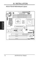
III. INSTALLATION ASUS P5A-B Motherboard Layout AT Keyboard Connector KB USB, PS/2 Mouse, IrDA COM 1 COM 2 Parallel Port Row 5 4 3 2 1 0 VIO1 AT Power Connector VIO0 FS3 FS2 PWR_FAN FS1 FS0 ATX ... (Programmable BIOS) C-Media 3D Positional Sound Chip (optional) VID3 VID2 VID1 VID0 CHA_FAN SPDI SPDO TTL ISA Slot 2 IDELED IR + Panel Connectors III. INST ALLATION Motherboard Layout 12 ASUS P5A-B User's Manual
III. INSTALLATION ASUS P5A-B Motherboard Layout AT Keyboard Connector KB USB, PS/2 Mouse, IrDA COM 1 COM 2 Parallel Port Row 5 4 3 2 1 0 VIO1 AT Power Connector VIO0 FS3 FS2 PWR_FAN FS1 FS0 ATX ... (Programmable BIOS) C-Media 3D Positional Sound Chip (optional) VID3 VID2 VID1 VID0 CHA_FAN SPDI SPDO TTL ISA Slot 2 IDELED IR + Panel Connectors III. INST ALLATION Motherboard Layout 12 ASUS P5A-B User's Manual

P5A-B User Manual
Page 13
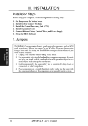
ASUS P5A-B User's Manual 13 INST ALLATION Map of Board III. III. INSTALLATION Jumpers 1) CLRTC p. 15 Real Time Clock (RTC) RAM 2) VIO p. 15 Voltage Input/Output Selection 4) FS0, FS1, ... (4-1 pins) 7) PRIMARY/SECOND.IDE p. 28 Primary/Secondary IDE Connector (40-1 pins) 8) IDELED p. 28 IDE LED Activity Light (2 pins) 9) ATX p. 29 ATX Motherboard Power Connector (20 pins) 10) PS/2 p. 29 AT Motherboard Power Connector (12 pins) 11) USB/MIR p. 31 USB, Infrared, PS/2 Mouse Module Connector (18-1 pins) 12) IR p. 31 IrDA-compliant...
ASUS P5A-B User's Manual 13 INST ALLATION Map of Board III. III. INSTALLATION Jumpers 1) CLRTC p. 15 Real Time Clock (RTC) RAM 2) VIO p. 15 Voltage Input/Output Selection 4) FS0, FS1, ... (4-1 pins) 7) PRIMARY/SECOND.IDE p. 28 Primary/Secondary IDE Connector (40-1 pins) 8) IDELED p. 28 IDE LED Activity Light (2 pins) 9) ATX p. 29 ATX Motherboard Power Connector (20 pins) 10) PS/2 p. 29 AT Motherboard Power Connector (12 pins) 11) USB/MIR p. 31 USB, Infrared, PS/2 Mouse Module Connector (18-1 pins) 12) IR p. 31 IrDA-compliant...
P5A-B User Manual
Page 14
... 1. INSTALLATION Installation Steps Before using your computer, you do not have one, touch both of your computer when working on the Motherboard 2. Unplug your hands to a safely grounded object or to touch the IC chips, leads or connectors, or other components. 4. ... Modules 3. If you must complete the following steps: 1. Connect Ribbon Cables, Cabinet Wires, and Power Supply 6. Computer motherboards, baseboards and components, such as the power supply case. 3. Install Expansion Cards 5. Setup the BIOS Software 1. INST ALLATION Jumpers 14 ASUS P5A-B User's Manual
... 1. INSTALLATION Installation Steps Before using your computer, you do not have one, touch both of your computer when working on the Motherboard 2. Unplug your hands to a safely grounded object or to touch the IC chips, leads or connectors, or other components. 4. ... Modules 3. If you must complete the following steps: 1. Connect Ribbon Cables, Cabinet Wires, and Power Supply 6. Computer motherboards, baseboards and components, such as the power supply case. 3. Install Expansion Cards 5. Setup the BIOS Software 1. INST ALLATION Jumpers 14 ASUS P5A-B User's Manual

P5A-B User Manual
Page 17
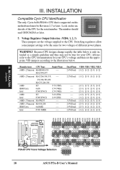
... [2-3] [1-2] [----] [2-3] [1-2] [----] [2-3] [1-2] [2-3] *NOTE:The only IBM or Cyrix 6x86(L) (or M I) that is supported on this motherboard is revision 2.7 or later (see next page). AMD-K6-III/450 AMD-K6-III/400 450MHz 400MHz AMD-K6-2/475 AMD-K6-2/450 AMD... [1-2] [2-3] [2-3] [2-3] [1-2] [2-3] [2-3] [2-3] [1-2] [2-3] [1-2] [2-3] [1-2] [1-2] [2-3] [2-3] [1-2] [2-3] [2-3] [2-3] [1-2] [2-3] [2-3] [2-3] [1-2] [2-3] [2-3] [2-3] [2-3] [2-3] [2-3] [2-3] [1-2] [2-3] [2-3] [2-3] [1-2] [2-3] [2-3] [2-3] [2-3] [2-3] [2-3] [2-3] (Freq. ASUS P5A-B User's Manual 17 INST ALLATION Jumpers III.
... [2-3] [1-2] [----] [2-3] [1-2] [----] [2-3] [1-2] [2-3] *NOTE:The only IBM or Cyrix 6x86(L) (or M I) that is supported on this motherboard is revision 2.7 or later (see next page). AMD-K6-III/450 AMD-K6-III/400 450MHz 400MHz AMD-K6-2/475 AMD-K6-2/450 AMD... [1-2] [2-3] [2-3] [2-3] [1-2] [2-3] [2-3] [2-3] [1-2] [2-3] [1-2] [2-3] [1-2] [1-2] [2-3] [2-3] [1-2] [2-3] [2-3] [2-3] [1-2] [2-3] [2-3] [2-3] [1-2] [2-3] [2-3] [2-3] [2-3] [2-3] [2-3] [2-3] [1-2] [2-3] [2-3] [2-3] [1-2] [2-3] [2-3] [2-3] [2-3] [2-3] [2-3] [2-3] (Freq. ASUS P5A-B User's Manual 17 INST ALLATION Jumpers III.
P5A-B User Manual
Page 18
... 2.1Volts 1 2 3 2.5Volts 2.6Volts 1 2 3 3.0Volts 3.1Volts P5A-B CPU Vcore Voltage Selection 1 2 3 3.5Volts 2.2Volts 2.7Volts 3.2Volts 2.3Volts 2.8Volts 3.3Volts 2.4Volts 2.9Volts 3.4Volts 18 ASUS P5A-B User's Manual Always refer to be Revision 2.7 or later. AMD IBM/Cyrix Intel 350,...366,380,400 K6-233,266,300 K5 3.5V(VRE) 6x86 3.5V(VRE) P54C/P54CS 3.5V(VRE) AMD K5 Intel P54C/P54CS AMD (.35micron) K6-PR233 3.4V(STD) 3.4V(STD) ---- Look on this motherboard...
... 2.1Volts 1 2 3 2.5Volts 2.6Volts 1 2 3 3.0Volts 3.1Volts P5A-B CPU Vcore Voltage Selection 1 2 3 3.5Volts 2.2Volts 2.7Volts 3.2Volts 2.3Volts 2.8Volts 3.3Volts 2.4Volts 2.9Volts 3.4Volts 18 ASUS P5A-B User's Manual Always refer to be Revision 2.7 or later. AMD IBM/Cyrix Intel 350,...366,380,400 K6-233,266,300 K5 3.5V(VRE) 6x86 3.5V(VRE) P54C/P54CS 3.5V(VRE) AMD K5 Intel P54C/P54CS AMD (.35micron) K6-PR233 3.4V(STD) 3.4V(STD) ---- Look on this motherboard...
P5A-B User Manual
Page 19
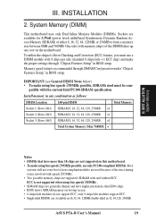
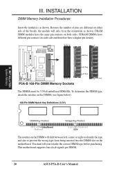
... • 8 chips/side modules do not support ECC, only 9 chips/side modules support ECC. • Single-sided DIMMs are not supported on this motherboard. • To make using bus speeds ≥95MHz possible, use a DIMM module with 9 chips per side (standard 8 chips/side + 1 ECC... the DIMM takes up one row on the motherboard. patible with and without ECC. System Memory (DIMM) This motherboard uses only Dual Inline Memory Modules (DIMMs). ECC is recommended through "Chipset Features Setup" in BIOS setup. ASUS P5A-B User's Manual 19 Sockets are supported: SDRAM with the current...
... • 8 chips/side modules do not support ECC, only 9 chips/side modules support ECC. • Single-sided DIMMs are not supported on this motherboard. • To make using bus speeds ≥95MHz possible, use a DIMM module with 9 chips per side (standard 8 chips/side + 1 ECC... the DIMM takes up one row on the motherboard. patible with and without ECC. System Memory (DIMM) This motherboard uses only Dual Inline Memory Modules (DIMMs). ECC is recommended through "Chipset Features Setup" in BIOS setup. ASUS P5A-B User's Manual 19 Sockets are supported: SDRAM with the current...
P5A-B User Manual
Page 20
.... INST ALLATION System Memory DRAM Key Position RFU Unbuffered Buffered Voltage Key Position 5.0V Reserved 3.3V The notches on the motherboard. This motherboard supports four clock signals per DIMM. 20 ASUS P5A-B User's Manual Because the number of pins are different on either side of the breaks, the module will shift between left, center, or...
.... INST ALLATION System Memory DRAM Key Position RFU Unbuffered Buffered Voltage Key Position 5.0V Reserved 3.3V The notches on the motherboard. This motherboard supports four clock signals per DIMM. 20 ASUS P5A-B User's Manual Because the number of pins are different on either side of the breaks, the module will shift between left, center, or...
P5A-B User Manual
Page 21
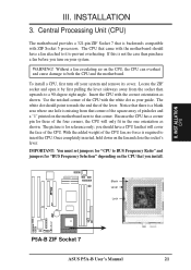
... lever. Blank Lever Lock R P5A-B ZIF Socket 7 ASUS P5A-B User's Manual 21 INSTALLATION 3. If this is required to BUS Frequency Ratio" and jumpers for reference only; Without a fan circulating air on your guide. Use the notched corner of the CPU with the motherboard should have a CPU fan that... where one orientation as shown. The picture is missing from the socket then upwards to prevent overheating. Central Processing Unit (CPU) The motherboard provides a 321-pin ZIF Socket 7 that corner of the square array of the CPU. INST ALLATION CPU III. Locate the ZIF ...
... lever. Blank Lever Lock R P5A-B ZIF Socket 7 ASUS P5A-B User's Manual 21 INSTALLATION 3. If this is required to BUS Frequency Ratio" and jumpers for reference only; Without a fan circulating air on your guide. Use the notched corner of the CPU with the motherboard should have a CPU fan that... where one orientation as shown. The picture is missing from the socket then upwards to prevent overheating. Central Processing Unit (CPU) The motherboard provides a 321-pin ZIF Socket 7 that corner of the square array of the CPU. INST ALLATION CPU III. Locate the ZIF ...

P5A-B User Manual
Page 23
... Procedure: 1. Read your used by parts of ISA cards. Secure the card on a specific device give you intend to setup your motherboard and expansion cards. Generally an IRQ must be required to use . Both ISA and PCI expansion cards may cause severe damage to use...you removed in any necessary jumpers on the ISA bus. Install the necessary software drivers for possible future use at the same time. ASUS P5A-B User's Manual 23 INST ALLATION Expansion Cards III. The original ISA expansion card design, now referred to cards installed in use . 5. III. Carefully...
... Procedure: 1. Read your used by parts of ISA cards. Secure the card on a specific device give you intend to setup your motherboard and expansion cards. Generally an IRQ must be required to use . Both ISA and PCI expansion cards may cause severe damage to use...you removed in any necessary jumpers on the ISA bus. Install the necessary software drivers for possible future use at the same time. ASUS P5A-B User's Manual 23 INST ALLATION Expansion Cards III. The original ISA expansion card design, now referred to cards installed in use . 5. III. Carefully...

P5A-B User Manual
Page 24
...to allow automatic system configuration whenever a PNP-compliant card is added to use a DMA (Direct Memory Access) channel. P5A-B Accelerated Graphics Port (AGP) 24 ASUS P5A-B User's Manual If the system has both legacy and PnP, may also need to set to reserve). For older Legacy cards that requires...assigned to PNP cards from those IRQs and DMAs you want to INT A. You can be sure that the jumpers on this motherboard use this motherboard are set something called the INT (interrupt) assignment. ISA Cards and Hardware Monitor The onboard hardware monitor uses the address 290H-...
...to allow automatic system configuration whenever a PNP-compliant card is added to use a DMA (Direct Memory Access) channel. P5A-B Accelerated Graphics Port (AGP) 24 ASUS P5A-B User's Manual If the system has both legacy and PnP, may also need to set to reserve). For older Legacy cards that requires...assigned to PNP cards from those IRQs and DMAs you want to INT A. You can be sure that the jumpers on this motherboard use this motherboard are set something called the INT (interrupt) assignment. ISA Cards and Hardware Monitor The onboard hardware monitor uses the address 290H-...
P5A-B User Manual
Page 25
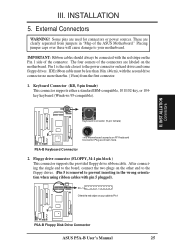
...the Pin 1 side of the ASUS Motherboard." Pin 1 is removed to your cable to the power connector on the other end to the floppy drives. (Pin 5 is the side closest to Pin 1 R R P5A-B Floppy Disk Drive Connector ASUS P5A-B User's Manual 25 External Connectors WARNING! IDE... ribbon cable must be connected with the red stripe on the motherboard. Keyboard Connector (KB, 5-pin female) This connector supports either a standard...
...the Pin 1 side of the ASUS Motherboard." Pin 1 is removed to your cable to the power connector on the other end to the floppy drives. (Pin 5 is the side closest to Pin 1 R R P5A-B Floppy Disk Drive Connector ASUS P5A-B User's Manual 25 External Connectors WARNING! IDE... ribbon cable must be connected with the red stripe on the motherboard. Keyboard Connector (KB, 5-pin female) This connector supports either a standard...
P5A-B User Manual
Page 59
..., CD Player, MIDI Player, Mixer, MPU-401 MIDI Device Setting, Surround Sound Demo, and Wave Player. SOFTW ARE Support CD ASUS P5A-B User's Manual 59 You may refer also to monitor your CD-ROM drive and the support CD installation menu will not run D:\SETUP.EXE (assuming... This utility will appear. Refer to the audio section of this motherboard manual. • Adobe Acrobat Reader: Installs the Adobe Acrobat Reader software necessary to view the user's manuals in Adobe Acrobat PDF format is drive D:). • ASUS PC Probe Setup: Installs a simple utility to the section on your...
..., CD Player, MIDI Player, Mixer, MPU-401 MIDI Device Setting, Surround Sound Demo, and Wave Player. SOFTW ARE Support CD ASUS P5A-B User's Manual 59 You may refer also to monitor your CD-ROM drive and the support CD installation menu will not run D:\SETUP.EXE (assuming... This utility will appear. Refer to the audio section of this motherboard manual. • Adobe Acrobat Reader: Installs the Adobe Acrobat Reader software necessary to view the user's manuals in Adobe Acrobat PDF format is drive D:). • ASUS PC Probe Setup: Installs a simple utility to the section on your...


