
P5-99VM User Manual
Page 8
... for multi-device connections. • IrDA: Supports an optional infrared port module for a wireless interface. 8 ASUS P5-99VM User's Manual FEA TURES Features II. FEATURES ASUS P5-99VM Motherboard The ASUS P5-99VM is available) pipelined-burst SRAM/ L2 memory cache and integrated Tag RAM to support Intel PC100compliant SDRAMs (8, 16... and with three DIMM sockets to make using the 100MHz bus speed possible. • USB: Supports the Universal Serial Bus standard through the onboard PCIset (South Bridge) and the ASUS PC Probe. • Ultra DMA/66 BM IDE: Comes with an onboard PCI Bus...
... for multi-device connections. • IrDA: Supports an optional infrared port module for a wireless interface. 8 ASUS P5-99VM User's Manual FEA TURES Features II. FEATURES ASUS P5-99VM Motherboard The ASUS P5-99VM is available) pipelined-burst SRAM/ L2 memory cache and integrated Tag RAM to support Intel PC100compliant SDRAMs (8, 16... and with three DIMM sockets to make using the 100MHz bus speed possible. • USB: Supports the Universal Serial Bus standard through the onboard PCIset (South Bridge) and the ASUS PC Probe. • Ultra DMA/66 BM IDE: Comes with an onboard PCI Bus...

P5-99VM User Manual
Page 11
FEA TURES Motherboard Parts II. FEATURES Parts of the ASUS P5-99VM Motherboard (T): Top (B): Bottom PS/2 Mouse (T) PS/2 Keyboard (B) USB Port 1 (T) USB Port 2 (B) Serial Port (COM1) (B) Parallel Port ATX 3 DIMM CPU ZIF Power Sockets Socket 7 SiS AGPset with Heatsink 8MB VGA Memory (not shown) L2 Cache Tag RAM (optional) VGA Connector (B) Audio Ports (T) Joystick/MIDI Connector (B) (optional) 3 PCI Slots Creative Audio CODEC (optional) ISA Programmable Super Multi-IO Creative Labs Serial Port Slot Flash ROM Audio (optional) (COM2) ASUS P5-99VM User's Manual 11 II.
FEA TURES Motherboard Parts II. FEATURES Parts of the ASUS P5-99VM Motherboard (T): Top (B): Bottom PS/2 Mouse (T) PS/2 Keyboard (B) USB Port 1 (T) USB Port 2 (B) Serial Port (COM1) (B) Parallel Port ATX 3 DIMM CPU ZIF Power Sockets Socket 7 SiS AGPset with Heatsink 8MB VGA Memory (not shown) L2 Cache Tag RAM (optional) VGA Connector (B) Audio Ports (T) Joystick/MIDI Connector (B) (optional) 3 PCI Slots Creative Audio CODEC (optional) ISA Programmable Super Multi-IO Creative Labs Serial Port Slot Flash ROM Audio (optional) (COM2) ASUS P5-99VM User's Manual 11 II.

P5-99VM User Manual
Page 12
H/W SETUP Motherboard Layout Dimmed components are optional. 12 ASUS P5-99VM User's Manual III. HARDWARE SETUP ASUS P5-99VM Motherboard Layout VID0 VID1 VID2 VID3 BF2 BF1 BF0 PARALLEL PORT ATX Power Connector PS/2 Top: Mouse Bottom: Keyboard USB Top: USB 1 Bottom: USB 2 COM1 KB_UP CPU Voltage CPU_FAN TagRAM SECONDARY IDE L2 Cache PRIMARY IDE FLOPPY FREQ MULT CPU ZIF...
H/W SETUP Motherboard Layout Dimmed components are optional. 12 ASUS P5-99VM User's Manual III. HARDWARE SETUP ASUS P5-99VM Motherboard Layout VID0 VID1 VID2 VID3 BF2 BF1 BF0 PARALLEL PORT ATX Power Connector PS/2 Top: Mouse Bottom: Keyboard USB Top: USB 1 Bottom: USB 2 COM1 KB_UP CPU Voltage CPU_FAN TagRAM SECONDARY IDE L2 Cache PRIMARY IDE FLOPPY FREQ MULT CPU ZIF...

P5-99VM User Manual
Page 13
III. ASUS P5-99VM User's Manual 13 H/W SETUP Contents III. HARDWARE SETUP Motherboard Settings 1) VIRQ p. 14 VGA Interrupt Selection (Enable/Disable) 2) VEN_DIS p. 14 VGA Setting (Enable/Disable) 3) LINEOUT_SW p. ... (15-Female) 7) FLOPPY p. 27 Floppy Drive Connector (34-1 pins) 8) GAME_AUDIO p. 27 Audio Port Connectors (Three 1/8" Female) 9) GAME_AUDIO p. 28 Joystick/MidiConnector (15-pin Female) 10) USB p. 28 Universal Serial BUS Ports 1 & 2 (Two 4-pin Female) 11) PRIMARY/SECOND.IDE p. 29 Primary/Secondary IDE Connector (40-1 pins) 12) ATX p. 30 ATX Motherboard Power...
III. ASUS P5-99VM User's Manual 13 H/W SETUP Contents III. HARDWARE SETUP Motherboard Settings 1) VIRQ p. 14 VGA Interrupt Selection (Enable/Disable) 2) VEN_DIS p. 14 VGA Setting (Enable/Disable) 3) LINEOUT_SW p. ... (15-Female) 7) FLOPPY p. 27 Floppy Drive Connector (34-1 pins) 8) GAME_AUDIO p. 27 Audio Port Connectors (Three 1/8" Female) 9) GAME_AUDIO p. 28 Joystick/MidiConnector (15-pin Female) 10) USB p. 28 Universal Serial BUS Ports 1 & 2 (Two 4-pin Female) 11) PRIMARY/SECOND.IDE p. 29 Primary/Secondary IDE Connector (40-1 pins) 12) ATX p. 30 ATX Motherboard Power...
P5-99VM User Manual
Page 28
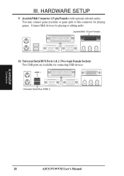
H/W SETUP Connectors 28 ASUS P5-99VM User's Manual Joystick/Midi (15-pin Female) 10. Universal Serial BUS Ports 1 & 2 (Two 4-pin Female Sockets) Two USB ports are available for playing or editing audio. HARDWARE SETUP 9. Connect Midi devices for connecting USB devices. USB 1 Universal Serial Bus (USB) 2 III. III. Joystick/Midi Connector (15-pin Female) (with optional onboard audio) You may connect game joysticks or game pads to this connector for playing games.
H/W SETUP Connectors 28 ASUS P5-99VM User's Manual Joystick/Midi (15-pin Female) 10. Universal Serial BUS Ports 1 & 2 (Two 4-pin Female Sockets) Two USB ports are available for playing or editing audio. HARDWARE SETUP 9. Connect Midi devices for connecting USB devices. USB 1 Universal Serial Bus (USB) 2 III. III. Joystick/Midi Connector (15-pin Female) (with optional onboard audio) You may connect game joysticks or game pads to this connector for playing games.

P5-99VM User Manual
Page 53
...that requires to determine if an ISA card is detected, the motherboard's Symbios BIOS will not function.) USB Function (Disabled) This motherboard supports Universal Serial Bus (USB) devices. BIOS SETUP ASUS P5-99VM User's Manual 53 Available options include: No/ICU and Yes. If you are not using that channel.... disable the motherboard's Symbios SCSI BIOS so that channel to save an extra IRQ# for each field is being used . (If your USB device. SYMBIOS SCSI BIOS (Auto) Auto allows the motherboard's BIOS to detect whether you are using an ICU to specify its default setting...
...that requires to determine if an ISA card is detected, the motherboard's Symbios BIOS will not function.) USB Function (Disabled) This motherboard supports Universal Serial Bus (USB) devices. BIOS SETUP ASUS P5-99VM User's Manual 53 Available options include: No/ICU and Yes. If you are not using that channel.... disable the motherboard's Symbios SCSI BIOS so that channel to save an extra IRQ# for each field is being used . (If your USB device. SYMBIOS SCSI BIOS (Auto) Auto allows the motherboard's BIOS to detect whether you are using an ICU to specify its default setting...

P5-99VM User Manual
Page 62
...in the DMI folder, Flash BIOS writer in the AFLASH folder, IDE Bus Master driver for improved performance under WIndows in the BUSMASTR folder, USB patch to change at any of our web sites. • Show Motherboard Information: Allows you to view the contents of the integrated VGA... audio drivers and utilities to view user's manuals saved in PDF format at any time without notice. S/W SETUP Windows 98 62 ASUS P5-99VM User's Manual Installation Menu • Install ASUS PC Probe Vx.xx: Installs a simple utility to monitor your motherboard, such as product name, BIOS version, and CPU. &#...
...in the DMI folder, Flash BIOS writer in the AFLASH folder, IDE Bus Master driver for improved performance under WIndows in the BUSMASTR folder, USB patch to change at any of our web sites. • Show Motherboard Information: Allows you to view the contents of the integrated VGA... audio drivers and utilities to view user's manuals saved in PDF format at any time without notice. S/W SETUP Windows 98 62 ASUS P5-99VM User's Manual Installation Menu • Install ASUS PC Probe Vx.xx: Installs a simple utility to monitor your motherboard, such as product name, BIOS version, and CPU. &#...
P5-99VM User Manual
Page 96
... be eliminated. APPENDIX UltraDMA/33 UltraDMA/33 is double of the PIO mode 4 or DMA mode 2. (16.6MB/s x2 = 33MB/s). APPENDIX Glossary 96 ASUS P5-99VM User's Manual With USB, the traditional complex cables from back panel of IDE command signal to transfer data, the DMA/33 uses both rising edge and falling edge...
... be eliminated. APPENDIX UltraDMA/33 UltraDMA/33 is double of the PIO mode 4 or DMA mode 2. (16.6MB/s x2 = 33MB/s). APPENDIX Glossary 96 ASUS P5-99VM User's Manual With USB, the traditional complex cables from back panel of IDE command signal to transfer data, the DMA/33 uses both rising edge and falling edge...


