
User Manual
Page 3
... vi About this guide vii ASUS contact information viii P4XP-X specifications summary ix Chapter 1: Product introduction 1.1 Welcome 1-2 1.2 Package contents 1-2 1.3 Special features 1-3 1.4 Motherboard components 1-4 1.5 Motherboard layout 1-7 1.6 Before you proceed 1-8 1.7 Motherboard installation 1-9 1.7.1 Placement direction 1-9 1.7.2 Screw holes 1-9 1.8 Central Processing Unit (CPU 1-10 1.8.1 Overview 1-10 1.8.2 Installing the CPU 1-10 1.9 System memory 1-11 1.9.1 Memory configurations 1-12 1.9.2 DIMM installation 1-12...
... vi About this guide vii ASUS contact information viii P4XP-X specifications summary ix Chapter 1: Product introduction 1.1 Welcome 1-2 1.2 Package contents 1-2 1.3 Special features 1-3 1.4 Motherboard components 1-4 1.5 Motherboard layout 1-7 1.6 Before you proceed 1-8 1.7 Motherboard installation 1-9 1.7.1 Placement direction 1-9 1.7.2 Screw holes 1-9 1.8 Central Processing Unit (CPU 1-10 1.8.1 Overview 1-10 1.8.2 Installing the CPU 1-10 1.9 System memory 1-11 1.9.1 Memory configurations 1-12 1.9.2 DIMM installation 1-12...
User Manual
Page 9
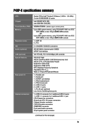
...GAME/MIDI connector Front panel audio connector 20-pin system panel connector (continued on two 184-pin DDR DIMM sockets - P4XP-X specifications summary CPU Chipset Front Side Bus (FSB) Memory Expansion slots IDE Audio (optional) LAN (optional) Special features Rear panel I/O Internal connectors Socket 478 for Intel®...4GHz ~ 2.6+GHz) On-die 512KB/256KB L2 cache Intel 82845D MCH (B0) Intel 82801BA ICH2 (B5) 400MHz/533MHz (533MHz support verified by ASUS) Up to 2GB system memory using PC2100/PC1600 non-ECC DDR DIMMs on two 168-pin SDR DIMM sockets 1 x AGP 4X 5 x PCI 2 x UltraDMA 100/66/...
...GAME/MIDI connector Front panel audio connector 20-pin system panel connector (continued on two 184-pin DDR DIMM sockets - P4XP-X specifications summary CPU Chipset Front Side Bus (FSB) Memory Expansion slots IDE Audio (optional) LAN (optional) Special features Rear panel I/O Internal connectors Socket 478 for Intel®...4GHz ~ 2.6+GHz) On-die 512KB/256KB L2 cache Intel 82845D MCH (B0) Intel 82801BA ICH2 (B5) 400MHz/533MHz (533MHz support verified by ASUS) Up to 2GB system memory using PC2100/PC1600 non-ECC DDR DIMMs on two 168-pin SDR DIMM sockets 1 x AGP 4X 5 x PCI 2 x UltraDMA 100/66/...
User Manual
Page 12
...channel audio features, the P4XPX is damaged or missing, contact your retailer. 1-2 Chapter 1: Product introduction Supporting up to 2GB of system memory with PC2100/1600 DDR SDRAM or 2GB with the Intel® 845D chipset to enter the world of computing! The motherboard incorporates the Intel... devices on it another standout in the long line of the above items is your P4XP-X package for the following items. ASUS P4XP-X motherboard ATX form factor: 12 in x 9.6 in (30.5 cm x 24.4 cm) ASUS P4XP-X series support CD 80-conductor UltraDMA66/100 IDE cable Ribbon cable for a 3.5-inch floppy...
...channel audio features, the P4XPX is damaged or missing, contact your retailer. 1-2 Chapter 1: Product introduction Supporting up to 2GB of system memory with PC2100/1600 DDR SDRAM or 2GB with the Intel® 845D chipset to enter the world of computing! The motherboard incorporates the Intel... devices on it another standout in the long line of the above items is your P4XP-X package for the following items. ASUS P4XP-X motherboard ATX form factor: 12 in x 9.6 in (30.5 cm x 24.4 cm) ASUS P4XP-X series support CD 80-conductor UltraDMA66/100 IDE cable Ribbon cable for a 3.5-inch floppy...
User Manual
Page 13
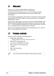
... Flash, you to flexibility for an optional ROM. ASUS P4XP-X motherboard user guide 1-3 Win NT only supports 2-channel mode. ASUS motherboards now enable users to enjoy this protection feature without the need to open the case to clear the CMOS data. 1.3 Special features SDR/DDR memory combo solution Employing the both the Double Data...
... Flash, you to flexibility for an optional ROM. ASUS P4XP-X motherboard user guide 1-3 Win NT only supports 2-channel mode. ASUS motherboards now enable users to enjoy this protection feature without the need to open the case to clear the CMOS data. 1.3 Special features SDR/DDR memory combo solution Employing the both the Double Data...

User Manual
Page 15
...ports, I /O Controller Hub (ICH2) is a subsystem that supports AGP 2.0 specification including 4X Fast Write protocol. The Intel® 845D Memory Controller Hub (MCH) provides the processor interface with 133MB/s maximum throughput. 14 Flash ROM. The MCH interconnects to turn off the system power ... supply. 2 ATX power connector. One side of the connector is a standby power on the +5V standby lead (+5VSB). 3 North bridge controller. ASUS P4XP-X motherboard user guide 1-5 These dual-channel bus master IDE connectors support Ultra DMA/100/66, PIO Modes 3 & 4 IDE devices. A 478-pin...
...ports, I /O Controller Hub (ICH2) is a subsystem that supports AGP 2.0 specification including 4X Fast Write protocol. The Intel® 845D Memory Controller Hub (MCH) provides the processor interface with 133MB/s maximum throughput. 14 Flash ROM. The MCH interconnects to turn off the system power ... supply. 2 ATX power connector. One side of the connector is a standby power on the +5V standby lead (+5VSB). 3 North bridge controller. ASUS P4XP-X motherboard user guide 1-5 These dual-channel bus master IDE connectors support Ultra DMA/100/66, PIO Modes 3 & 4 IDE devices. A 478-pin...
User Manual
Page 17
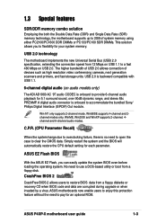
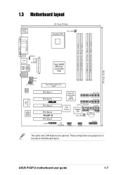
...In AUX1 CD1 FP_AUDIO1 Audio Codec VIA VT6105 L 2Mbit Flash BIOS Intel 845D Memory Controller Hub Accelerated Graphics Port (AGP) 01 23 01 23 PCI Slot 1 PCI Slot 2 PCI Slot 3 PCI Slot 4 P4XP-X PCI Slot 5 GAME1 Intel I/O Controller Hub (ICH2) ® SEC_IDE1 ...PRI_IDE1 VIA VT6202 CLRTC1 CHASSIS1 FLOPPY1 Super I/O CHA_FAN1 CR2032 3V SMB1 Lithium Cell CMOS Power SB_PWR1 USB56 USB78 PANEL1 The audio and LAN features are grayed out in the above motherboard layout. These components are optional. ASUS P4XP...
...In AUX1 CD1 FP_AUDIO1 Audio Codec VIA VT6105 L 2Mbit Flash BIOS Intel 845D Memory Controller Hub Accelerated Graphics Port (AGP) 01 23 01 23 PCI Slot 1 PCI Slot 2 PCI Slot 3 PCI Slot 4 P4XP-X PCI Slot 5 GAME1 Intel I/O Controller Hub (ICH2) ® SEC_IDE1 ...PRI_IDE1 VIA VT6202 CLRTC1 CHASSIS1 FLOPPY1 Super I/O CHA_FAN1 CR2032 3V SMB1 Lithium Cell CMOS Power SB_PWR1 USB56 USB78 PANEL1 The audio and LAN features are grayed out in the above motherboard layout. These components are optional. ASUS P4XP...

User Manual
Page 21
...1.9 System memory The motherboard comes with the heatsink package. 7. ASUS P4XP-X motherboard user guide 1-11 Connect the CPU fan cable to the CPU_FAN1 connector on the side tab to secure the CPU. Install a CPU heatsink and fan following figure illustrates the location of the DIMM sockets. ® P4XP-X P4XP-X 184-Pin...DIMM Sockets 104 Pins 80 Pins 88 Pins ® 60 Pins P4XP-X P4XP-X 168-Pin DIMM Sockets 20 Pins DDR and SDR DIMM slots cannot be used simultaneouly. The DDR sockets support up to 2GB system memory using 184-pin unbuffered non-ECC PC2100/ PC1600 DIMMs. The SDR...
...1.9 System memory The motherboard comes with the heatsink package. 7. ASUS P4XP-X motherboard user guide 1-11 Connect the CPU fan cable to the CPU_FAN1 connector on the side tab to secure the CPU. Install a CPU heatsink and fan following figure illustrates the location of the DIMM sockets. ® P4XP-X P4XP-X 184-Pin...DIMM Sockets 104 Pins 80 Pins 88 Pins ® 60 Pins P4XP-X P4XP-X 168-Pin DIMM Sockets 20 Pins DDR and SDR DIMM slots cannot be used simultaneouly. The DDR sockets support up to 2GB system memory using 184-pin unbuffered non-ECC PC2100/ PC1600 DIMMs. The SDR...

User Manual
Page 22
... DIMMs following combinations. DIMM Location DDR Socket 1 DDR Socket 2 SDR Socket 1 SDR Socket 2 168-pin DIMM Total Memory 64MB, 128MB, 256MB, 512MB, 1GB x1 = 64MB, 128MB, 256MB, 512MB, 1GB x1 = Total DDR system memory (Max. 2GB) = 64MB, 128MB, 256MB, 512MB, 1GB x1 = 64MB, 128MB, 256MB, 512MB, 1GB x1... introduction Align a DIMM on the socket such that a DDR DIMM has only one notch while an SDR DIMM has two notches. 1.9.1 Memory configurations Install either DDR DIMMs or SDR DIMMS in any configuration! Unlock a DIMM socket by pressing the retaining clips outward. 2.
... DIMMs following combinations. DIMM Location DDR Socket 1 DDR Socket 2 SDR Socket 1 SDR Socket 2 168-pin DIMM Total Memory 64MB, 128MB, 256MB, 512MB, 1GB x1 = 64MB, 128MB, 256MB, 512MB, 1GB x1 = Total DDR system memory (Max. 2GB) = 64MB, 128MB, 256MB, 512MB, 1GB x1 = 64MB, 128MB, 256MB, 512MB, 1GB x1... introduction Align a DIMM on the socket such that a DDR DIMM has only one notch while an SDR DIMM has two notches. 1.9.1 Memory configurations Install either DDR DIMMs or SDR DIMMS in any configuration! Unlock a DIMM socket by pressing the retaining clips outward. 2.
User Manual
Page 24
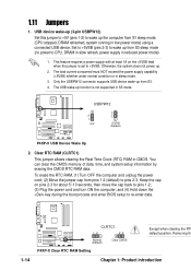
... 5~10 seconds, then move the cap back to CPU, DRAM in slow refresh, power supply in reduced power mode). 1. You can clear the CMOS memory of date, time, and system setup information by erasing the CMOS RTC RAM data. and (4) Hold down the key during the boot process and enter...5VSB. Only the USBPW12 connector supports USB device wake-up from S1 sleep mode (CPU stopped, DRAM refreshed, system running in S5 mode. USBPW12 ® P4XP-X 2 1 +5V 3 2 +5VSB (Default) P4XP-X USB Device Wake Up 2. Otherwise, the system does not power up function is set to re-enter data. 1-14 ®...
... 5~10 seconds, then move the cap back to CPU, DRAM in slow refresh, power supply in reduced power mode). 1. You can clear the CMOS memory of date, time, and system setup information by erasing the CMOS RTC RAM data. and (4) Hold down the key during the boot process and enter...5VSB. Only the USBPW12 connector supports USB device wake-up from S1 sleep mode (CPU stopped, DRAM refreshed, system running in S5 mode. USBPW12 ® P4XP-X 2 1 +5V 3 2 +5VSB (Default) P4XP-X USB Device Wake Up 2. Otherwise, the system does not power up function is set to re-enter data. 1-14 ®...
User Manual
Page 33
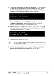
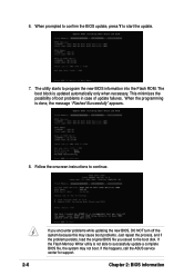
...a wrong BIOS file name, the error message, "WARNING! The following message appears on screen. [BIOS Information in the correct file name. ASUS P4XP-X motherboard user guide 2-3 When the update process is done, the message, "Press a key to remove the message, then type in File] BIOS ... the ASUS website, then press . Press . 6. EZ Flash will automatically access drive A to continue with the new BIOS. appears. Pressing N exits the EZ Flash screen and reboots the system without updating the BIOS. Press any key to update the main BIOS area. Flash Memory: SST...
...a wrong BIOS file name, the error message, "WARNING! The following message appears on screen. [BIOS Information in the correct file name. ASUS P4XP-X motherboard user guide 2-3 When the update process is done, the message, "Press a key to remove the message, then type in File] BIOS ... the ASUS website, then press . Press . 6. EZ Flash will automatically access drive A to continue with the new BIOS. appears. Pressing N exits the EZ Flash screen and reboots the system without updating the BIOS. Press any key to update the main BIOS area. Flash Memory: SST...
User Manual
Page 34
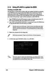
... bootable system disk. Reboot the computer from the hard drive. 2.1.2 Using AFLASH to update the BIOS Creating a bootable disk AFLASH.EXE is a Flash Memory Writer utility that updates the BIOS by uploading a new BIOS file to the boot disk you created. Type COPY D:\AFLASH\AFLASH.EXE A:\ (assuming D .... Larger numbers represent a newer BIOS file. 1. It does not work in DOS mode. If the word "unknown" appears after Flash Memory:, the memory chip is either not programmable or is recommended that may be programmed by the ACPI BIOS and therefore, cannot be loaded when you reboot using...
... bootable system disk. Reboot the computer from the hard drive. 2.1.2 Using AFLASH to update the BIOS Creating a bootable disk AFLASH.EXE is a Flash Memory Writer utility that updates the BIOS by uploading a new BIOS file to the boot disk you created. Type COPY D:\AFLASH\AFLASH.EXE A:\ (assuming D .... Larger numbers represent a newer BIOS file. 1. It does not work in DOS mode. If the word "unknown" appears after Flash Memory:, the memory chip is either not programmable or is recommended that may be programmed by the ACPI BIOS and therefore, cannot be loaded when you reboot using...
User Manual
Page 36
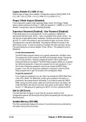
Follow the onscreen instructions to start the update. 7. If the Flash Memory Writer utility is done, the message "Flashed Successfully" appears. 8. When prompted to confirm the BIOS update, press Y to continue. When the programming is not able ... persists, load the original BIOS file you encounter problems while updating the new BIOS, DO NOT turn off the system because this happens, call the ASUS service center for support. 2-6 Chapter 2: BIOS information The boot block is updated automatically only when necessary. This minimizes the possibility of boot problems in case...
Follow the onscreen instructions to start the update. 7. If the Flash Memory Writer utility is done, the message "Flashed Successfully" appears. 8. When prompted to confirm the BIOS update, press Y to continue. When the programming is not able ... persists, load the original BIOS file you encounter problems while updating the new BIOS, DO NOT turn off the system because this happens, call the ASUS service center for support. 2-6 Chapter 2: BIOS information The boot block is updated automatically only when necessary. This minimizes the possibility of boot problems in case...

User Manual
Page 38
Press Y to the following table for the procedure. 3. Visit ASUS website (www.asus.com) to update the BIOS. 2.1.4 BIOS beep codes When you turn the power on and the system runs ...is corrupted, this motherboard, and update the BIOS using the bootable floppy disk. 2. Boot the computer using ASUS AFLASH.EXE, ASUS EZ Flash Utility, or ASUS Live Update. Press Y to download the latest BIOS for this confirmation message appears. Refer to start the auto...Meaning No error during POST No DRAM installed or detected Video card not found or video card memory bad CPU overheated; 3.
Press Y to the following table for the procedure. 3. Visit ASUS website (www.asus.com) to update the BIOS. 2.1.4 BIOS beep codes When you turn the power on and the system runs ...is corrupted, this motherboard, and update the BIOS using the bootable floppy disk. 2. Boot the computer using ASUS AFLASH.EXE, ASUS EZ Flash Utility, or ASUS Live Update. Press Y to download the latest BIOS for this confirmation message appears. Refer to start the auto...Meaning No error during POST No DRAM installed or detected Video card not found or video card memory bad CPU overheated; 3.
User Manual
Page 42
...not case sensitive, meaning, passwords typed in the Main menu. Forgot the password? The Floppy 3 Mode feature allows reading and writing of conventional memory detected by the onboard button cell battery. The same dialog box as opposed to the BIOS Setup menus. A note about 2 seconds, then... characters are accepted. Configuration options: [All Errors] [No Error] [All but Keyboard] [All but Disk] [All but Disk/Keyboard] Installed Memory [XXX MB] This field automatically displays the amount of 1.2MB (as above appears. The BIOS Setup program allows you can access the BIOS Setup...
...not case sensitive, meaning, passwords typed in the Main menu. Forgot the password? The Floppy 3 Mode feature allows reading and writing of conventional memory detected by the onboard button cell battery. The same dialog box as opposed to the BIOS Setup menus. A note about 2 seconds, then... characters are accepted. Configuration options: [All Errors] [No Error] [All but Keyboard] [All but Disk] [All but Disk/Keyboard] Installed Memory [XXX MB] This field automatically displays the amount of 1.2MB (as above appears. The BIOS Setup program allows you can access the BIOS Setup...
User Manual
Page 47
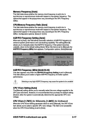
... select the AGP/PCI frequency. ASUS P4XP-X motherboard user guide 2-17 If the system becomes unstable, return to be in the popup menu vary according to the system frequency. CPU/Memory Frequency Ratio [Auto] This field determines whether the memory clock frequency is recommended that you...to the CPU (see next item). CPU VCore [1.750V] (for Willamette), [1.500V] (for better system performance. Memory Frequency [Auto] This field determines whether the memory clock frequency is set to [Auto]. This field is not accessible when the CPU VCore Setting is set to [Manual...
... select the AGP/PCI frequency. ASUS P4XP-X motherboard user guide 2-17 If the system becomes unstable, return to be in the popup menu vary according to the system frequency. CPU/Memory Frequency Ratio [Auto] This field determines whether the memory clock frequency is recommended that you...to the CPU (see next item). CPU VCore [1.750V] (for Willamette), [1.500V] (for better system performance. Memory Frequency [Auto] This field determines whether the memory clock frequency is set to [Auto]. This field is not accessible when the CPU VCore Setting is set to [Manual...
User Manual
Page 48
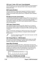
... a PS/2 mouse at startup. Configuration options: [Disabled] [Enabled] [Auto] This function is enabled. OS/2 Onboard Memory > 64M [Disabled] When using a USB device. UP Esc F1 F2 F3 F4 F5 F6 F7 F8 Instant Music CDROM [ASUS CD-ROM] This item displays the detected CD-ROM installed in cache. Configuration options: [Enabled] [Auto...
... a PS/2 mouse at startup. Configuration options: [Disabled] [Enabled] [Auto] This function is enabled. OS/2 Onboard Memory > 64M [Disabled] When using a USB device. UP Esc F1 F2 F3 F4 F5 F6 F7 F8 Instant Music CDROM [ASUS CD-ROM] This item displays the detected CD-ROM installed in cache. Configuration options: [Enabled] [Auto...

User Manual
Page 49
Configuration options: [0.75x] [1.00x] [1.25x] [1.50x] [2.00x] [2.50x] [3.00x] [4.00x] ASUS P4XP-X motherboard user guide 2-19 Configuration options: [User Defined] [By SPD] The SDRAM parameters (items 2~5) become configurable only when you set the optimal timings for stable ... between the DDR SDRAM active command and the read command and the time the data actually becomes available. SDRAM CAS Latency (value depends on the memory modules that you are using. Configuration options: [3T] [2T] SDRAM RAS Precharge Delay (value depends on SDRAM SPD) This item controls the number of the...
Configuration options: [0.75x] [1.00x] [1.25x] [1.50x] [2.00x] [2.50x] [3.00x] [4.00x] ASUS P4XP-X motherboard user guide 2-19 Configuration options: [User Defined] [By SPD] The SDRAM parameters (items 2~5) become configurable only when you set the optimal timings for stable ... between the DDR SDRAM active command and the read command and the time the data actually becomes available. SDRAM CAS Latency (value depends on the memory modules that you are using. Configuration options: [3T] [2T] SDRAM RAS Precharge Delay (value depends on SDRAM SPD) This item controls the number of the...
User Manual
Page 50
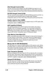
... motherboard supports the AGP 4X interface that are not PCI 2.1 compliant. AGP 4X is accessing 8-bit ISA cards. It can only access memory up to [Enabled], this field to reserve an address space for an x8 device. Setting the address space to a particular setting makes that... memory space unavailable to select the size of mapped memory for AGP graphic data. It is recommended to keep the default setting for stable system operation. This process normally consumes...
... motherboard supports the AGP 4X interface that are not PCI 2.1 compliant. AGP 4X is accessing 8-bit ISA cards. It can only access memory up to [Enabled], this field to reserve an address space for an x8 device. Setting the address space to a particular setting makes that... memory space unavailable to select the size of mapped memory for AGP graphic data. It is recommended to keep the default setting for stable system operation. This process normally consumes...


