Motherboard DIY Troubleshooting Guide
Page 1
P4V8X-X Motherboard
P4V8X-X Motherboard
P4V8X-X User Manual
Page 1
Motherboard P4V8X-X User Guide
Motherboard P4V8X-X User Guide
P4V8X-X User Manual
Page 3
...v Safety information vi About this guide vii ASUS contact information viii P4V8X-X specifications summary ix Chapter 1: Product introduction 1.1 Welcome 1-2 1.2 Package contents 1-2 1.3 Special features 1-2 1.4 Motherboard components 1-4 1.5 Motherboard layout 1-7 1.6 Before you proceed 1-8 1.7 Motherboard installation 1-9 1.7.1 Placement direction 1-9 1.7.2 Screw...configurations 1-13 1.10 Expansion slots 1-14 1.10.1 Standard interrupt assignments 1-14 1.10.2 IRQ assignments for this motherboard 1-14 1.10.3 PCI slots 1-15 1.10.4 AGP slot 1-15 1.11 Jumper 1-16 1.12 Connectors ...
...v Safety information vi About this guide vii ASUS contact information viii P4V8X-X specifications summary ix Chapter 1: Product introduction 1.1 Welcome 1-2 1.2 Package contents 1-2 1.3 Special features 1-2 1.4 Motherboard components 1-4 1.5 Motherboard layout 1-7 1.6 Before you proceed 1-8 1.7 Motherboard installation 1-9 1.7.1 Placement direction 1-9 1.7.2 Screw...configurations 1-13 1.10 Expansion slots 1-14 1.10.1 Standard interrupt assignments 1-14 1.10.2 IRQ assignments for this motherboard 1-14 1.10.3 PCI slots 1-15 1.10.4 AGP slot 1-15 1.11 Jumper 1-16 1.12 Connectors ...

P4V8X-X User Manual
Page 6
... • Avoid dust, humidity, and temperature extremes. If you add a device. • Before connecting or removing signal cables from the motherboard, ensure that all cables are correctly connected and the power cables are not damaged. If you are not sure about the voltage of the electrical... outlet you are using, contact your retailer. Operation safety • Before installing the motherboard and adding devices on a stable surface. • If you encounter technical problems with the package. • Before using the product, make...
... • Avoid dust, humidity, and temperature extremes. If you add a device. • Before connecting or removing signal cables from the motherboard, ensure that all cables are correctly connected and the power cables are not damaged. If you are not sure about the voltage of the electrical... outlet you are using, contact your retailer. Operation safety • Before installing the motherboard and adding devices on a stable surface. • If you encounter technical problems with the package. • Before using the product, make...
P4V8X-X User Manual
Page 11
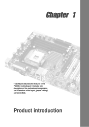
Product introduction Chapter 1 This chapter describes the features of the layout, jumper settings, and connectors. It includes brief descriptions of the motherboard components, and illustrations of the P4V8X-X motherboard.
Product introduction Chapter 1 This chapter describes the features of the layout, jumper settings, and connectors. It includes brief descriptions of the motherboard components, and illustrations of the P4V8X-X motherboard.
P4V8X-X User Manual
Page 12
...standout in 478-pin package coupled with the VIA® P4X533 chipset to set a new benchmark for the following items. ASUS P4V8X-X motherboard ASUS P4V8X-X series support CD UltraDMA 133/100/66 cable Floppy disk cable I/O shield Bag of extra jumper caps User Guide If any... your affordable vehicle to enter the world of computing! The ASUS P4V8X-X motherboard delivers a host of new features and latest technologies making it , check the items in your package with support for buying the ASUS® P4V8X-X motherboard! The P4V8X-X incorporates the Intel® Pentium® 4 / Celeron processors...
...standout in 478-pin package coupled with the VIA® P4X533 chipset to set a new benchmark for the following items. ASUS P4V8X-X motherboard ASUS P4V8X-X series support CD UltraDMA 133/100/66 cable Floppy disk cable I/O shield Bag of extra jumper caps User Guide If any... your affordable vehicle to enter the world of computing! The ASUS P4V8X-X motherboard delivers a host of new features and latest technologies making it , check the items in your package with support for buying the ASUS® P4V8X-X motherboard! The P4V8X-X incorporates the Intel® Pentium® 4 / Celeron processors...
P4V8X-X User Manual
Page 13
.../2700/2100 non-ECC DDR DIMMs to deliver up to 3.2GB/s data transfer rateto provide enhanced system performance. USB 2.0 technology The motherboard implements the new Universal Serial Bus (USB) 2.0 specification, extending the connection speed from a floppy diskette or recovery CD when BIOS...protection feature without the need to pay for 5.1 surround sound and over 90dB dynamic range. See page 1-18. ASUS P4V8X-X motherboard 1-3 DDR400 memory support The motherboard supports up to 3GB of system memory using a user-friendly graphical user interface for an easier and faster RAID installation...
.../2700/2100 non-ECC DDR DIMMs to deliver up to 3.2GB/s data transfer rateto provide enhanced system performance. USB 2.0 technology The motherboard implements the new Universal Serial Bus (USB) 2.0 specification, extending the connection speed from a floppy diskette or recovery CD when BIOS...protection feature without the need to pay for 5.1 surround sound and over 90dB dynamic range. See page 1-18. ASUS P4V8X-X motherboard 1-3 DDR400 memory support The motherboard supports up to 3GB of system memory using a user-friendly graphical user interface for an easier and faster RAID installation...
P4V8X-X User Manual
Page 14
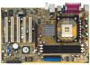
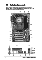
1.4 Motherboard components Before you install the motherboard, learn about its major components and available features to the succeeding pages for the component descriptions. 1 23 4 5 6 7 16 8 15 9 14 10 13 12 11 17 18 19 20 21 22 27 26 1-4 25 24 23 Chapter 1: Product introduction Refer to facilitate the installation and future upgrades.
1.4 Motherboard components Before you install the motherboard, learn about its major components and available features to the succeeding pages for the component descriptions. 1 23 4 5 6 7 16 8 15 9 14 10 13 12 11 17 18 19 20 21 22 27 26 1-4 25 24 23 Chapter 1: Product introduction Refer to facilitate the installation and future upgrades.
P4V8X-X User Manual
Page 15
...Intel® Pentium® 4 or Celeron® processors, with 800*/533/400 MHz frequency, system memory interface at least 1A on the motherboard. This LED lights up to 150MB/s data transfer rate using unbuffered non-ECC PC3200/2700/2100 DDR DIMMs. 5 ATX power connector. This ...This LED acts as a reminder to an ATX power supply. This Low Pin Count (LPC) interface provides the commonly used Super I /O controller. ASUS P4V8X-X motherboard 1-5 This 20-pin connector connects to turn off the system power before plugging or unplugging devices. 12 Flash ROM. One side of the connector is...
...Intel® Pentium® 4 or Celeron® processors, with 800*/533/400 MHz frequency, system memory interface at least 1A on the motherboard. This LED lights up to 150MB/s data transfer rate using unbuffered non-ECC PC3200/2700/2100 DDR DIMMs. 5 ATX power connector. This ...This LED acts as a reminder to an ATX power supply. This Low Pin Count (LPC) interface provides the commonly used Super I /O controller. ASUS P4V8X-X motherboard 1-5 This 20-pin connector connects to turn off the system power before plugging or unplugging devices. 12 Flash ROM. One side of the connector is...
P4V8X-X User Manual
Page 18
... from the wall socket before touching any component, place it on them due to the motherboard, peripherals, and/or components. Whenever you install or remove any motherboard component. ® P4V8X-X P4V8X-X Onboard LED SB_PWR1 ON Standby Power OFF Powered Off Install only 0.8V and 1.5V ...AGP cards on this motherboard to prevent damage to avoid damaging them . 4. Hold components by the edges...
... from the wall socket before touching any component, place it on them due to the motherboard, peripherals, and/or components. Whenever you install or remove any motherboard component. ® P4V8X-X P4V8X-X Onboard LED SB_PWR1 ON Standby Power OFF Powered Off Install only 0.8V and 1.5V ...AGP cards on this motherboard to prevent damage to avoid damaging them . 4. Hold components by the edges...
P4V8X-X User Manual
Page 19
... of the chassis as indicated in the correct orientation. The edge with external ports goes to the rear part of the chassis ASUS P4V8X-X motherboard 1-9 1.7 Motherboard installation Before you place it . The motherboard uses the ATX form factor that measures 12 inches x 7.6 inches (30.5 cm x 19.3 cm). Make sure to unplug the power cord before...
... of the chassis as indicated in the correct orientation. The edge with external ports goes to the rear part of the chassis ASUS P4V8X-X motherboard 1-9 1.7 Motherboard installation Before you place it . The motherboard uses the ATX form factor that measures 12 inches x 7.6 inches (30.5 cm x 19.3 cm). Make sure to unplug the power cord before...
P4V8X-X User Manual
Page 20
This motherboard supports Intel Pentium 4 CPUs with an 800MHz FSB CPU, enable the CPU Compatible Mode item in the BIOS to lower FSB frequency. Reboot the computer. 1-... section "2.4.1 JumperFree configuration" for details. • Incorrect installation of the CPU socket. ® P4V8X-X P4V8X-X Socket 478 Gold Arrow • If the system becomes unstable when overclocking with Hyper-Threading Technology. 2. Install the CPU. 2. For more information on this motherboard: 1. It is supported under Windows XP and later versions only. 3. Hyper-Threading Technology...
This motherboard supports Intel Pentium 4 CPUs with an 800MHz FSB CPU, enable the CPU Compatible Mode item in the BIOS to lower FSB frequency. Reboot the computer. 1-... section "2.4.1 JumperFree configuration" for details. • Incorrect installation of the CPU socket. ® P4V8X-X P4V8X-X Socket 478 Gold Arrow • If the system becomes unstable when overclocking with Hyper-Threading Technology. 2. Install the CPU. 2. For more information on this motherboard: 1. It is supported under Windows XP and later versions only. 3. Hyper-Threading Technology...
P4V8X-X User Manual
Page 21
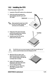
... 90°- 100° angle. Gold Mark The CPU fits only in one correct orientation. Locate the 478-pin ZIF socket on the motherboard. Socket Lever Make sure that it fits in place. 1.8.2 Installing the CPU Follow these steps to 90°-100° angle, otherwise ... DO NOT force the CPU into the socket until it is locked. 6. When the CPU is lifted up to the CPU_FAN1 connector on the motherboard. 2. ASUS P4V8X-X motherboard 1-11 Unlock the socket by pressing the lever sideways, then lift it up to install a CPU. 1. Position the CPU above the socket such...
... 90°- 100° angle. Gold Mark The CPU fits only in one correct orientation. Locate the 478-pin ZIF socket on the motherboard. Socket Lever Make sure that it fits in place. 1.8.2 Installing the CPU Follow these steps to 90°-100° angle, otherwise ... DO NOT force the CPU into the socket until it is locked. 6. When the CPU is lifted up to the CPU_FAN1 connector on the motherboard. 2. ASUS P4V8X-X motherboard 1-11 Unlock the socket by pressing the lever sideways, then lift it up to install a CPU. 1. Position the CPU above the socket such...
P4V8X-X User Manual
Page 22
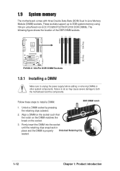
1.9 System memory The motherboard comes with three Double Data Rate (DDR) Dual In-Line Memory Module (DIMM) sockets. Align a DIMM on the socket such that the notch on the DIMM matches the break on the socket. 3. DIMM1 DIMM2 DIMM3 104 Pins 80 Pins ® P4V8X-X P4V8X-X 184-Pin DDR DIMM Sockets 1.9.1 Installing a DIMM Make... figure shows the location of the DDR DIMM sockets. Unlock a DIMM socket by pressing the retaining clips outward. 2. These sockets support up to both the motherboard and the components.
1.9 System memory The motherboard comes with three Double Data Rate (DDR) Dual In-Line Memory Module (DIMM) sockets. Align a DIMM on the socket such that the notch on the DIMM matches the break on the socket. 3. DIMM1 DIMM2 DIMM3 104 Pins 80 Pins ® P4V8X-X P4V8X-X 184-Pin DDR DIMM Sockets 1.9.1 Installing a DIMM Make... figure shows the location of the DDR DIMM sockets. Unlock a DIMM socket by pressing the retaining clips outward. 2. These sockets support up to both the motherboard and the components.
P4V8X-X User Manual
Page 23
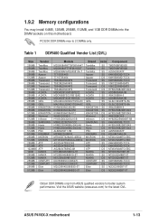
PC3200 DDR DIMMs max to 2 DIMMs only. Visit the ASUS website (www.asus.com) for better system performance. 1.9.2 Memory configurations You may install 64MB, 128MB, 256MB, 512MB, and 1GB DDR DIMMs into the DIMM sockets on this motherboard. Table 1 DDR400 Qualified Vendor List (QVL) Size Vendor 256MB 256MB 256MB 256MB 512MB 256MB 256MB 512MB... NANYA DS NT5DS32M8BT-5T CENTURY SS K4H560838D-TCCC CENTURY DS K4H560838D-TCCC Elixir SS N2DS25680BT-5T Elixir DS N2DS25680BT-5T Obtain DDR DIMMs only from ASUS qualified vendors for the latest QVL. ASUS P4V8X-X motherboard 1-13
PC3200 DDR DIMMs max to 2 DIMMs only. Visit the ASUS website (www.asus.com) for better system performance. 1.9.2 Memory configurations You may install 64MB, 128MB, 256MB, 512MB, and 1GB DDR DIMMs into the DIMM sockets on this motherboard. Table 1 DDR400 Qualified Vendor List (QVL) Size Vendor 256MB 256MB 256MB 256MB 512MB 256MB 256MB 512MB... NANYA DS NT5DS32M8BT-5T CENTURY SS K4H560838D-TCCC CENTURY DS K4H560838D-TCCC Elixir SS N2DS25680BT-5T Elixir DS N2DS25680BT-5T Obtain DDR DIMMs only from ASUS qualified vendors for the latest QVL. ASUS P4V8X-X motherboard 1-13
P4V8X-X User Manual
Page 24
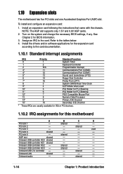
...9 Primary IDE Channel 15* 10 Secondary IDE Channel * These IRQs are usually available for ISA or PCI devices. 1.10.2 IRQ assignments for this motherboard A B C D PCI slot 1 - Onboard USB controller HC0 shared - - - To install and configure an expansion card: 1. PCI slot ...Install the drivers and/or software applications for BIOS information. 3. Onboard audio - - Onboard LAN shared - - - 1.10 Expansion slots The motherboard has five PCI slots and one Accelerated Graphics Port (AGP) slot. shared - - Turn on the system and change the necessary BIOS settings,...
...9 Primary IDE Channel 15* 10 Secondary IDE Channel * These IRQs are usually available for ISA or PCI devices. 1.10.2 IRQ assignments for this motherboard A B C D PCI slot 1 - Onboard USB controller HC0 shared - - - To install and configure an expansion card: 1. PCI slot ...Install the drivers and/or software applications for BIOS information. 3. Onboard audio - - Onboard LAN shared - - - 1.10 Expansion slots The motherboard has five PCI slots and one Accelerated Graphics Port (AGP) slot. shared - - Turn on the system and change the necessary BIOS settings,...
P4V8X-X User Manual
Page 25
...five 32-bit PCI slots on your motherboard. This motherboard does not support 3.3V AGP cards. ® P4V8X-X Keyed for one with PCI specifications. 1.10.4 AGP slot This motherboard has an Accelerated Graphics Port (AGP) slot that they fit the AGP slot on this motherboard. The slots support PCI cards such ...other cards that comply with +1.5V or +0.8V specification. When you buy an AGP card, make sure that you ask for 1.5v P4V8X-X Accelerated Graphics Port (AGP) ASUS P4V8X-X motherboard 1-15 Note the notches on the card golden fingers to ensure that supports AGP 8X/4X cards.
...five 32-bit PCI slots on your motherboard. This motherboard does not support 3.3V AGP cards. ® P4V8X-X Keyed for one with PCI specifications. 1.10.4 AGP slot This motherboard has an Accelerated Graphics Port (AGP) slot that they fit the AGP slot on this motherboard. The slots support PCI cards such ...other cards that comply with +1.5V or +0.8V specification. When you buy an AGP card, make sure that you ask for 1.5v P4V8X-X Accelerated Graphics Port (AGP) ASUS P4V8X-X motherboard 1-15 Note the notches on the card golden fingers to ensure that supports AGP 8X/4X cards.
P4V8X-X User Manual
Page 27
... the internal USB header that can connect to support this feature. USBPW12 USBPW34 12 23 +5V (Default) +5VSB ® P4V8X-X USBPW78 USBPW56 12 23 +5V P4V8X-X USB Device Wake Up (Default) +5VSB ASUS P4V8X-X motherboard 1-17 USB device wake-up the computer from S1 sleep mode (CPU stopped, DRAM refreshed, system running in low power...
... the internal USB header that can connect to support this feature. USBPW12 USBPW34 12 23 +5V (Default) +5VSB ® P4V8X-X USBPW78 USBPW56 12 23 +5V P4V8X-X USB Device Wake Up (Default) +5VSB ASUS P4V8X-X motherboard 1-17 USB device wake-up the computer from S1 sleep mode (CPU stopped, DRAM refreshed, system running in low power...
P4V8X-X User Manual
Page 28
... connectors on the floppy ribbon cable to PIN 1. After connecting one end to the motherboard, connect the other end to the floppy drive. (Pin 5 is removed to 150 MB/s data transfer rate, faster than the standard parallel ATA with pin 5 plug). ® P4V8X-X PIN 1 FLOPPY1 NOTE: Orient the red markings on the...
... connectors on the floppy ribbon cable to PIN 1. After connecting one end to the motherboard, connect the other end to the floppy drive. (Pin 5 is removed to 150 MB/s data transfer rate, faster than the standard parallel ATA with pin 5 plug). ® P4V8X-X PIN 1 FLOPPY1 NOTE: Orient the red markings on the...
P4V8X-X User Manual
Page 29
... with two ribbon cables - Pin 20 on the IDE ribbon cable to the secondary IDE connector. BIOS supports specific device bootup. PIN 1 ASUS P4V8X-X motherboard 1-19 IDE connectors (40-1 pin PRI_IDE, SEC_IDE) This connector supports the provided UltraDMA100/66 IDE ribbon cable. 3. If you install two ... disks, you connect non-UltraDMA100/66 devices to PIN 1. For UltraDMA100/66 IDE devices, use the 80-conductor IDE cable. ® P4V8X-X P4V8X-X IDE Connectors SEC_IDE1 PRI_IDE1 NOTE: Orient the red markings (usually zigzag) on each IDE connector is intentional. 3. one for the primary ...
... with two ribbon cables - Pin 20 on the IDE ribbon cable to the secondary IDE connector. BIOS supports specific device bootup. PIN 1 ASUS P4V8X-X motherboard 1-19 IDE connectors (40-1 pin PRI_IDE, SEC_IDE) This connector supports the provided UltraDMA100/66 IDE ribbon cable. 3. If you install two ... disks, you connect non-UltraDMA100/66 devices to PIN 1. For UltraDMA100/66 IDE devices, use the 80-conductor IDE cable. ® P4V8X-X P4V8X-X IDE Connectors SEC_IDE1 PRI_IDE1 NOTE: Orient the red markings (usually zigzag) on each IDE connector is intentional. 3. one for the primary ...


