
Motherboard DIY Troubleshooting Guide
Page 27
® P4V800-X PIN 1 FLOPPY1 P4V800-X Floppy Disk Drive Connector CPU_FAN1 GND +12V Rotation P4V800-X CHA_FAN1 Rotation +12V GND P4V800-X 12-Volt Fan Connectors 1-17
® P4V800-X PIN 1 FLOPPY1 P4V800-X Floppy Disk Drive Connector CPU_FAN1 GND +12V Rotation P4V800-X CHA_FAN1 Rotation +12V GND P4V800-X 12-Volt Fan Connectors 1-17

Motherboard DIY Troubleshooting Guide
Page 59
Select Screen Select Item Enter Go to Sub-screen F1 General Help F10 Save and Exit ESC Exit Boot Device Priority 1st Boot Device 2nd Boot Device [First Floppy Drive] [PM-ST320413A] Specifies the boot sequence from the available devices. A device enclosed in parenthesis has been disabled in the corresponding type menu. Change Option F1 General Help F10 Save and Exit ESC Exit 2-27 Select Screen Select Item +- Boot Settings Boot Device Priority Boot Settings Configuration Security Specifies the Boot Device Priority sequence.
Select Screen Select Item Enter Go to Sub-screen F1 General Help F10 Save and Exit ESC Exit Boot Device Priority 1st Boot Device 2nd Boot Device [First Floppy Drive] [PM-ST320413A] Specifies the boot sequence from the available devices. A device enclosed in parenthesis has been disabled in the corresponding type menu. Change Option F1 General Help F10 Save and Exit ESC Exit 2-27 Select Screen Select Item +- Boot Settings Boot Device Priority Boot Settings Configuration Security Specifies the Boot Device Priority sequence.
Motherboard DIY Troubleshooting Guide
Page 69
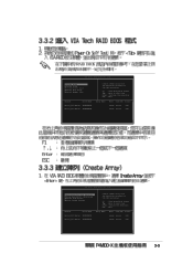
...attached to VIA IDE controller F1 : View Array/Disk Status , : Move to next item Enter: Confirm the selection ESC : Exit Channel Drive Name Serial_Ch0 Master XXXXXXXXXX Serial_Ch1 Master XXXXXXXXXX Array Name Mode Size(GB) Status xxxxx xxx.xx Hdd xxxxx xxx.xx Hdd 3-5 RAID BIOS Ver... 1.XX Create Array Delete Array Create/Delete Spare Select Boot Array Serial Number View Channel Drive Name Serial_Ch0 Master XXXXXXXXXX Serial_Ch1 Master XXXXXXXXXX Create a RAID array with the hard disk attached to VIA IDE controller F1 : View Array/Disk...
...attached to VIA IDE controller F1 : View Array/Disk Status , : Move to next item Enter: Confirm the selection ESC : Exit Channel Drive Name Serial_Ch0 Master XXXXXXXXXX Serial_Ch1 Master XXXXXXXXXX Array Name Mode Size(GB) Status xxxxx xxx.xx Hdd xxxxx xxx.xx Hdd 3-5 RAID BIOS Ver... 1.XX Create Array Delete Array Create/Delete Spare Select Boot Array Serial Number View Channel Drive Name Serial_Ch0 Master XXXXXXXXXX Serial_Ch1 Master XXXXXXXXXX Create a RAID array with the hard disk attached to VIA IDE controller F1 : View Array/Disk...

Motherboard DIY Troubleshooting Guide
Page 71
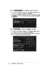
Continue? Are you sure? Continue? Press Y/N The selected drives will be destroyed. Press Y/N 3-7 Create only Create and duplicate The data on the selected disks will be destroyed.
Continue? Are you sure? Continue? Press Y/N The selected drives will be destroyed. Press Y/N 3-7 Create only Create and duplicate The data on the selected disks will be destroyed.
Motherboard DIY Troubleshooting Guide
Page 72
... XXXXXXXXXX xxxxx xxx.xx Hdd VIA Tech. RAID BIOS Ver 1.xx Create Array Delete Array Create/Delete Spare Select Boot Array Serial Number View Channel Drive Name Serial_Ch0 Master XXXXXXXXXX Serial_Ch1 Master XXXXXXXXXX Create a RAID array with the hard disk attached to VIA IDE controller F1 : View Array/Disk Status , : Move...
... XXXXXXXXXX xxxxx xxx.xx Hdd VIA Tech. RAID BIOS Ver 1.xx Create Array Delete Array Create/Delete Spare Select Boot Array Serial Number View Channel Drive Name Serial_Ch0 Master XXXXXXXXXX Serial_Ch1 Master XXXXXXXXXX Create a RAID array with the hard disk attached to VIA IDE controller F1 : View Array/Disk Status , : Move...
P4V800-X User Manual
Page 15
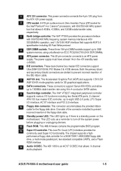
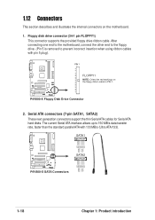
... Low Pin Count (LPC) interface provides the commonly used Super I /O interface, AC'97 interface and PCI 2.2 interface. 10 Floppy disk connector. ASUS P4V800-X motherboard user guide 1-5 This 20-pin connector connects to turn off the system power before plugging or unplugging devices. 12 Flash ROM. One side ... at least 1A on the motherboard. A 478-pin surface mount, Zero Insertion Force (ZIF) socket for a 360K/720K/1.44M/2.88M floppy disk drive, a multi-mode parallel port, two standard compatible UARTs, and a Flash ROM interface. 14 Audio CODEC. The VIA® PT800 provides the ...
... Low Pin Count (LPC) interface provides the commonly used Super I /O interface, AC'97 interface and PCI 2.2 interface. 10 Floppy disk connector. ASUS P4V800-X motherboard user guide 1-5 This 20-pin connector connects to turn off the system power before plugging or unplugging devices. 12 Flash ROM. One side ... at least 1A on the motherboard. A 478-pin surface mount, Zero Insertion Force (ZIF) socket for a 360K/720K/1.44M/2.88M floppy disk drive, a multi-mode parallel port, two standard compatible UARTs, and a Flash ROM interface. 14 Audio CODEC. The VIA® PT800 provides the ...
P4V800-X User Manual
Page 28
... SATA1, SATA2) These next generation connectors support the thin Serial ATA cables for Serial ATA hard disks. P4V800-X Floppy Disk Drive Connector 2. After connecting one end to the motherboard, connect the other end to the floppy drive. (Pin 5 is removed to prevent incorrect insertion when using ribbon cables with 133 MB/s (Ultra ATA...
... SATA1, SATA2) These next generation connectors support the thin Serial ATA cables for Serial ATA hard disks. P4V800-X Floppy Disk Drive Connector 2. After connecting one end to the motherboard, connect the other end to the floppy drive. (Pin 5 is removed to prevent incorrect insertion when using ribbon cables with 133 MB/s (Ultra ATA...
P4V800-X User Manual
Page 29
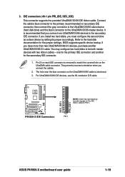
...purchase another for the jumper settings. 3. It is recommended that you connect the cables. 2. BIOS supports specific device bootup. PIN 1 ASUS P4V800-X motherboard user guide 1-19 Connect the cable's blue connector to the primary (recommended) or secondary IDE connector, then connect the gray connector... to the UltraDMA100/66 slave device (hard disk drive) and the black connector to be both master devices with two ribbon cables - This prevents incorrect orientation when you connect non...
...purchase another for the jumper settings. 3. It is recommended that you connect the cables. 2. BIOS supports specific device bootup. PIN 1 ASUS P4V800-X motherboard user guide 1-19 Connect the cable's blue connector to the primary (recommended) or secondary IDE connector, then connect the gray connector... to the UltraDMA100/66 slave device (hard disk drive) and the black connector to be both master devices with two ribbon cables - This prevents incorrect orientation when you connect non...
P4V800-X User Manual
Page 36
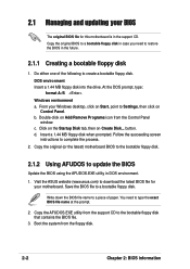
... floppy disk into the drive. button. Follow the succeeding screen instructions to a bootable floppy disk. Copy the AFUDOS.EXE utility from the floppy disk. 2-2 Chapter 2: BIOS information Save the BIOS file to complete the process. 2. You need to Settings, then click on Control Panel. Visit the ASUS website (www.asus.com) to download...
... floppy disk into the drive. button. Follow the succeeding screen instructions to a bootable floppy disk. Copy the AFUDOS.EXE utility from the floppy disk. 2-2 Chapter 2: BIOS information Save the BIOS file to complete the process. 2. You need to Settings, then click on Control Panel. Visit the ASUS website (www.asus.com) to download...
P4V800-X User Manual
Page 39
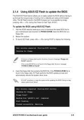
The EZ Flash is built-in the drive, the error message "Floppy not found!" Reboot the system. 3. Starting BIOS recovery... If there is no floppy disk found in the floppy disk, EZ Flash ... so may cause system boot failure! Checking for floppy... Start flashing... ASUS P4V800-X motherboard user guide 2-5 To launch EZ Flash, press + during the Power-On Self Tests (POST). If the P4V800-X.ROM file is found in the floppy disk, the error message "P4V800-X.ROM not found ! Rebooting. User recovery requested. Floppy found !" 4. User recovery...
The EZ Flash is built-in the drive, the error message "Floppy not found!" Reboot the system. 3. Starting BIOS recovery... If there is no floppy disk found in the floppy disk, EZ Flash ... so may cause system boot failure! Checking for floppy... Start flashing... ASUS P4V800-X motherboard user guide 2-5 To launch EZ Flash, press + during the Power-On Self Tests (POST). If the P4V800-X.ROM file is found in the floppy disk, the error message "P4V800-X.ROM not found ! Rebooting. User recovery requested. Floppy found !" 4. User recovery...
P4V800-X User Manual
Page 41
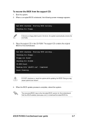
... system. Checking for CD-ROM... DO NOT shutdown or reset the system while updating the BIOS! ASUS P4V800-X motherboard user guide 2-7 Boot the system. 2. CD-ROM found in the CD-ROM. Place the support CD in the drive, the system automatically checks the CD-ROM. 3. Starting BIOS recovery... Checking for floppy... Doing so...
... system. Checking for CD-ROM... DO NOT shutdown or reset the system while updating the BIOS! ASUS P4V800-X motherboard user guide 2-7 Boot the system. 2. CD-ROM found in the CD-ROM. Place the support CD in the drive, the system automatically checks the CD-ROM. 3. Starting BIOS recovery... Checking for floppy... Doing so...
P4V800-X User Manual
Page 45
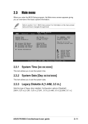
.... 2.3.2 System Date [Day xx/xx/xxxx] This item allows you an overview of floppy drive installed. Change Field Tab Select Field F1 General Help F10 Save and Exit ESC Exit 2.3.1 ...27/2003] [1.44M, 3.5 in] Primary IDE Master Primary IDE Slave Secondary IDE Master Secondary IDE Slave System Information :[ST320413A] :[ASUS CD-S340] :[Not Detected] :[Not Detected] Use [ENTER], [TAB] or [SHIFT-TAB] to navigate through them. Configuration options...system information. Use [+] or [-] to set the system date. 2.3.3 Legacy Diskette A [1.44M, 3.5 in .] ASUS P4V800-X motherboard user guide 2-11
.... 2.3.2 System Date [Day xx/xx/xxxx] This item allows you an overview of floppy drive installed. Change Field Tab Select Field F1 General Help F10 Save and Exit ESC Exit 2.3.1 ...27/2003] [1.44M, 3.5 in] Primary IDE Master Primary IDE Slave Secondary IDE Master Secondary IDE Slave System Information :[ST320413A] :[ASUS CD-S340] :[Not Detected] :[Not Detected] Use [ENTER], [TAB] or [SHIFT-TAB] to navigate through them. Configuration options...system information. Use [+] or [-] to set the system date. 2.3.3 Legacy Diskette A [1.44M, 3.5 in .] ASUS P4V800-X motherboard user guide 2-11
P4V800-X User Manual
Page 46
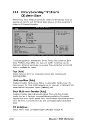
... Block (Multi-sector Transfer) PIO Mode DMA Mode Smart Monitoring 32Bit Data Transfer [Auto] [Auto] [Auto] [Auto] [Auto] [Auto] [Disabled] Select the type of IDE drive. These items show N/A if no IDE device is a separate sub-menu for each IDE device. Setting to display the IDE device information. Configuration options: [Disabled...
... Block (Multi-sector Transfer) PIO Mode DMA Mode Smart Monitoring 32Bit Data Transfer [Auto] [Auto] [Auto] [Auto] [Auto] [Auto] [Disabled] Select the type of IDE drive. These items show N/A if no IDE device is a separate sub-menu for each IDE device. Setting to display the IDE device information. Configuration options: [Disabled...
P4V800-X User Manual
Page 50
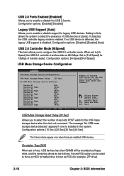
... General Help F10 Save and Exit ESC Exit USB Mass Storage Reset Delay [20 Sec] Allows you to enable or disable support for example, ZIP drive). 2-16 Chapter 2: BIOS information Configuration options: [Enabled] [Disabled] Legacy USB Support [Auto] Allows you to select the number of USB devices at 480 ... you to configure the USB 2.0 controller mode. When set to Auto, USB devices less than 530MB will be used to force an HDD formatted drive to [Full-Speed] for 12Mbps of seconds POST waits for the USB mass storage device after that start unit command. Emulation Type [N/A] When set...
... General Help F10 Save and Exit ESC Exit USB Mass Storage Reset Delay [20 Sec] Allows you to enable or disable support for example, ZIP drive). 2-16 Chapter 2: BIOS information Configuration options: [Enabled] [Disabled] Legacy USB Support [Auto] Allows you to select the number of USB devices at 480 ... you to configure the USB 2.0 controller mode. When set to Auto, USB devices less than 530MB will be used to force an HDD formatted drive to [Full-Speed] for 12Mbps of seconds POST waits for the USB mass storage device after that start unit command. Emulation Type [N/A] When set...

P4V800-X User Manual
Page 60
... The Boot menu items allow you to Sub-screen F1 General Help F10 Save and Exit ESC Exit Removable Drives This item is displayed only when two or more removable drives are installed. 2.6.1 Boot Device Priority Boot Device Priority 1st Boot Device 2nd Boot Device [First Floppy...then press Enter to display the sub-menu. Configuration options: [xxxxx Drive] [Disabled] 2-26 Chapter 2: BIOS information Change Option F1 General Help F10 Save and Exit ESC Exit 1st ~ xxth Boot Device [1st Floppy Drive] These items specify the boot device priority sequence from the available devices...
... The Boot menu items allow you to Sub-screen F1 General Help F10 Save and Exit ESC Exit Removable Drives This item is displayed only when two or more removable drives are installed. 2.6.1 Boot Device Priority Boot Device Priority 1st Boot Device 2nd Boot Device [First Floppy...then press Enter to display the sub-menu. Configuration options: [xxxxx Drive] [Disabled] 2-26 Chapter 2: BIOS information Change Option F1 General Help F10 Save and Exit ESC Exit 1st ~ xxth Boot Device [1st Floppy Drive] These items specify the boot device priority sequence from the available devices...
P4V800-X User Manual
Page 66
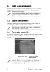
.... The CD automatically displays the Drivers menu if Autorun is NOT enabled in your hardware. Refer to run the CD. 3-2 Chapter 3: Software support Visit the ASUS website for general reference only. Double-click the ASSETUP.EXE to your OS documentation for more information If Autorun is enabled in your CD-ROM...
.... The CD automatically displays the Drivers menu if Autorun is NOT enabled in your hardware. Refer to run the CD. 3-2 Chapter 3: Software support Visit the ASUS website for general reference only. Double-click the ASSETUP.EXE to your OS documentation for more information If Autorun is enabled in your CD-ROM...
P4V800-X User Manual
Page 67
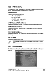
...100Mbps Fast Ethernet driver to support USB 2.0. 3.2.3 Utilities menu The Utilities menu shows the applications and other software that the motherboard supports. ASUS P4V800-X motherboard user guide 3-3 VIA Registry (INF) driver - VIA RAID Controller driver This item installs the VIA RAID controller driver and application...shows the available device drivers if the system detects installed devices. Install the necessary drivers to configure and manage disk drives. VIA PCI IRQ Miniport driver AD1980 SoundMAX Audio Driver This item installs the ADI 1980 AC'97 compliant audio controller and application....
...100Mbps Fast Ethernet driver to support USB 2.0. 3.2.3 Utilities menu The Utilities menu shows the applications and other software that the motherboard supports. ASUS P4V800-X motherboard user guide 3-3 VIA Registry (INF) driver - VIA RAID Controller driver This item installs the VIA RAID controller driver and application...shows the available device drivers if the system detects installed devices. Install the necessary drivers to configure and manage disk drives. VIA PCI IRQ Miniport driver AD1980 SoundMAX Audio Driver This item installs the ADI 1980 AC'97 compliant audio controller and application....
P4V800-X User Manual
Page 69
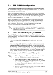
... creating RAID configurations. 3.3.1 Install the Serial ATA (SATA) hard disks The VIA® VT8237 southbridge chipset supports Serial ATA hard disk drives. 3.3 RAID 0 / RAID 1 configurations The motherboard includes a high performance IDE RAID controller integrated in the other hard disk has 60GB... (striping) array for perfomance, use two new drives. • If you are new cables. RAID 0 (called data mirroring) copies and maintains an identical image of data from the motherboard support CD to the entire system. ASUS P4V800-X motherboard user guide 3-5 For example, one hard...
... creating RAID configurations. 3.3.1 Install the Serial ATA (SATA) hard disks The VIA® VT8237 southbridge chipset supports Serial ATA hard disk drives. 3.3 RAID 0 / RAID 1 configurations The motherboard includes a high performance IDE RAID controller integrated in the other hard disk has 60GB... (striping) array for perfomance, use two new drives. • If you are new cables. RAID 0 (called data mirroring) copies and maintains an identical image of data from the motherboard support CD to the entire system. ASUS P4V800-X motherboard user guide 3-5 For example, one hard...
P4V800-X User Manual
Page 70
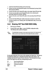
... Tech. The message describes the function of Serial ATA cable to navigate through the setup menu options. Connect the other end of each drive. 7. Connect the other end of the screen is for the next procedure. 3.3.2 Entering VIA® Tech RAID BIOS Utility 1. Boot... ATA connector (SATA2). 5. RAID BIOS Ver 1.XX Create Array Delete Array Create/Delete Spare Select Boot Array Serial Number View Channel Drive Name Serial_Ch0 Master XXXXXXXXXX Serial_Ch1 Master XXXXXXXXXX Create a RAID array with their corresponding functions. Connect one end of the second Serial ATA ...
... Tech. The message describes the function of Serial ATA cable to navigate through the setup menu options. Connect the other end of each drive. 7. Connect the other end of the screen is for the next procedure. 3.3.2 Entering VIA® Tech RAID BIOS Utility 1. Boot... ATA connector (SATA2). 5. RAID BIOS Ver 1.XX Create Array Delete Array Create/Delete Spare Select Boot Array Serial Number View Channel Drive Name Serial_Ch0 Master XXXXXXXXXX Serial_Ch1 Master XXXXXXXXXX Create a RAID array with their corresponding functions. Connect one end of the second Serial ATA ...
P4V800-X User Manual
Page 71
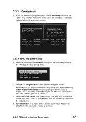
... are replaced with create array menu options. RAID BIOS Ver 1.xx Auto Setup For Data Security Array Mode RAID 1 (Mirroring) Select Disk Drives Start Create Process Create a RAID array with next step, otherwise, proceed to auto-configure the RAID array by selecting Auto Setup for Performance ... VIA IDE controller F1 : View Array/Disk Status , : Move to display the RAID system setting pop-up menu. ASUS P4V800-X motherboard user guide 3-7 Use arrow keys to select disk drive/s, then press to set array block size. 3.3.3 Create Array 1. In the VIA RAID BIOS utility main menu, select ...
... are replaced with create array menu options. RAID BIOS Ver 1.xx Auto Setup For Data Security Array Mode RAID 1 (Mirroring) Select Disk Drives Start Create Process Create a RAID array with next step, otherwise, proceed to auto-configure the RAID array by selecting Auto Setup for Performance ... VIA IDE controller F1 : View Array/Disk Status , : Move to display the RAID system setting pop-up menu. ASUS P4V800-X motherboard user guide 3-7 Use arrow keys to select disk drive/s, then press to set array block size. 3.3.3 Create Array 1. In the VIA RAID BIOS utility main menu, select ...


