P4V800-X User Manual
Page 12
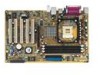
...to 3GB of computing! Thank you start installing the motherboard, and hardware devices on it another standout in your affordable vehicle to set a new benchmark for the following items. ASUS P4V800-X motherboard ASUS P4V800-X series support CD UltraDMA 133/100/66 cable 2 x Serial ...ATA cables Floppy disk cable I/O shield Bag of extra jumper caps User Guide If any of ASUS quality motherboards! Before you for the Intel® next generation Prescott CPU. The ASUS P4V800-X motherboard ...
...to 3GB of computing! Thank you start installing the motherboard, and hardware devices on it another standout in your affordable vehicle to set a new benchmark for the following items. ASUS P4V800-X motherboard ASUS P4V800-X series support CD UltraDMA 133/100/66 cable 2 x Serial ...ATA cables Floppy disk cable I/O shield Bag of extra jumper caps User Guide If any of ASUS quality motherboards! Before you for the Intel® next generation Prescott CPU. The ASUS P4V800-X motherboard ...
P4V800-X User Manual
Page 13
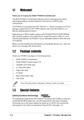
...10/100 LAN The onboard LAN controller is onboard to provide efficient power management for an optional ROM. ASUS P4V800-X motherboard user guide 1-3 DDR400 memory support The motherboard supports up to 3GB of system memory using a user-friendly graphical user interface for an easier and faster ...RAID installation and management. Serial ATA technology The motherboard bundles the new Serial ATA technology through the SATA ...
...10/100 LAN The onboard LAN controller is onboard to provide efficient power management for an optional ROM. ASUS P4V800-X motherboard user guide 1-3 DDR400 memory support The motherboard supports up to 3GB of system memory using a user-friendly graphical user interface for an easier and faster ...RAID installation and management. Serial ATA technology The motherboard bundles the new Serial ATA technology through the SATA ...
P4V800-X User Manual
Page 15
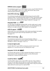
...ribbon cable for 3D graphical applications. 8 SATA connectors. This Low Pin Count (LPC) interface provides the commonly used Super I /O controller. ASUS P4V800-X motherboard user guide 1-5 A 478-pin surface mount, Zero Insertion Force (ZIF) socket for a 360K/720K/1.44M/2.88M floppy disk drive, a ... connectors are slotted to 3GB system memory using thin 4-conductor SATA cables. 9 South bridge controller. These dual-channel bus master IDE connectors support Ultra DMA133/100/66, PIO Modes 3 & 4 IDE devices. This 4Mb firmware contains the programmable BIOS program. 13 Super I /O ...
...ribbon cable for 3D graphical applications. 8 SATA connectors. This Low Pin Count (LPC) interface provides the commonly used Super I /O controller. ASUS P4V800-X motherboard user guide 1-5 A 478-pin surface mount, Zero Insertion Force (ZIF) socket for a 360K/720K/1.44M/2.88M floppy disk drive, a ... connectors are slotted to 3GB system memory using thin 4-conductor SATA cables. 9 South bridge controller. These dual-channel bus master IDE connectors support Ultra DMA133/100/66, PIO Modes 3 & 4 IDE devices. This 4Mb firmware contains the programmable BIOS program. 13 Super I /O ...
P4V800-X User Manual
Page 20
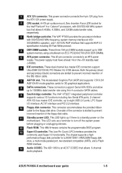
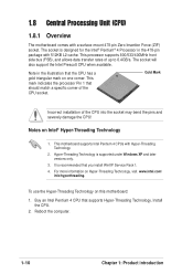
... Technology, visit www.intel.com/ info/hyperthreading. The socket will also support the Intel Prescott CPU when available. This mark indicates the processor Pin 1 that the CPU has a gold triangular mark on this motherboard: 1. For more information on Intel® Hyper-Threading Technology 1. Install... To use the Hyper-Threading Technology on one corner. Buy an Intel Pentium 4 CPU that you install WinXP Service Pack 1. 4. This motherboard supports Intel Pentium 4 CPUs with a surface mount 478-pin Zero Insertion Force (ZIF) socket. Note in the 478-pin package with 512KB ...
... Technology, visit www.intel.com/ info/hyperthreading. The socket will also support the Intel Prescott CPU when available. This mark indicates the processor Pin 1 that the CPU has a gold triangular mark on this motherboard: 1. For more information on Intel® Hyper-Threading Technology 1. Install... To use the Hyper-Threading Technology on one corner. Buy an Intel Pentium 4 CPU that you install WinXP Service Pack 1. 4. This motherboard supports Intel Pentium 4 CPUs with a surface mount 478-pin Zero Insertion Force (ZIF) socket. Note in the 478-pin package with 512KB ...
P4V800-X User Manual
Page 22
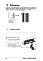
These sockets support up to unplug the power supply before adding or removing DIMMs... properly Unlocked Retaining Clip seated. 1-12 Chapter 1: Product introduction DIMM1 DIMM2 DIMM3 104 Pins 80 Pins ® P4V800-X P4V800-X 184-Pin DDR DIMM Sockets 1.9.1 Installing a DIMM Make sure to 3GB system memory using 184-pin unbuffered non... of the DDR DIMM sockets. Follow these steps to both the motherboard and the components. Unlock a DIMM socket by pressing the retaining clips outward. 2. 1.9 System memory The motherboard comes with three Double Data Rate (DDR) Dual In-Line Memory...
These sockets support up to unplug the power supply before adding or removing DIMMs... properly Unlocked Retaining Clip seated. 1-12 Chapter 1: Product introduction DIMM1 DIMM2 DIMM3 104 Pins 80 Pins ® P4V800-X P4V800-X 184-Pin DDR DIMM Sockets 1.9.1 Installing a DIMM Make sure to 3GB system memory using 184-pin unbuffered non... of the DDR DIMM sockets. Follow these steps to both the motherboard and the components. Unlock a DIMM socket by pressing the retaining clips outward. 2. 1.9 System memory The motherboard comes with three Double Data Rate (DDR) Dual In-Line Memory...
P4V800-X User Manual
Page 24
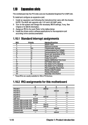
...motherboard A B C D PCI slot 1 - Assign an IRQ to the tables below. 4. PCI slot 3 - - - shared - - Onboard USB controller HC0 shared - - - shared - - Onboard audio - - shared - Onboard USB controller HC3 - PCI slot 5 - Onboard USB controller HC1 shared - - - Onboard LAN shared - - - To install and configure an expansion card: 1. NOTE: The AGP slot supports... 2 - - AGP slot shared - - - shared - 1.10 Expansion slots The motherboard has five PCI slots and one Accelerated Graphics Port (AGP) slot. Install an expansion card...
...motherboard A B C D PCI slot 1 - Assign an IRQ to the tables below. 4. PCI slot 3 - - - shared - - Onboard USB controller HC0 shared - - - shared - - Onboard audio - - shared - Onboard USB controller HC3 - PCI slot 5 - Onboard USB controller HC1 shared - - - Onboard LAN shared - - - To install and configure an expansion card: 1. NOTE: The AGP slot supports... 2 - - AGP slot shared - - - shared - 1.10 Expansion slots The motherboard has five PCI slots and one Accelerated Graphics Port (AGP) slot. Install an expansion card...
P4V800-X User Manual
Page 25
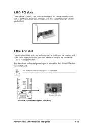
... or +0.8V specification. When you ask for 1.5v, 0.8v P4V800-X Accelerated Graphics Port (AGP) ASUS P4V800-X motherboard user guide 1-15 The slots support PCI cards such as a LAN card, SCSI card, USB card, and other cards that comply with PCI specifications. 1.10.4 AGP slot This motherboard has an Accelerated Graphics Port (AGP) slot that you buy...
... or +0.8V specification. When you ask for 1.5v, 0.8v P4V800-X Accelerated Graphics Port (AGP) ASUS P4V800-X motherboard user guide 1-15 The slots support PCI cards such as a LAN card, SCSI card, USB card, and other cards that comply with PCI specifications. 1.10.4 AGP slot This motherboard has an Accelerated Graphics Port (AGP) slot that you buy...
P4V800-X User Manual
Page 27
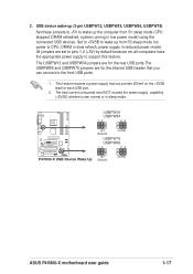
... sleep mode (no power to support this feature. The total current consumed must NOT exceed the power supply capability (+5VSB) whether under normal or in reduced power mode). USBPW12 USBPW34 12 23 ® P4V800-X +5V (Default) +5VSB USBPW78 USBPW56 12 23 +5V P4V800-X USB Device Wake Up (Default) +5VSB ASUS P4V800-X motherboard user guide 1-17 All...
... sleep mode (no power to support this feature. The total current consumed must NOT exceed the power supply capability (+5VSB) whether under normal or in reduced power mode). USBPW12 USBPW34 12 23 ® P4V800-X +5V (Default) +5VSB USBPW78 USBPW56 12 23 +5V P4V800-X USB Device Wake Up (Default) +5VSB ASUS P4V800-X motherboard user guide 1-17 All...
P4V800-X User Manual
Page 28
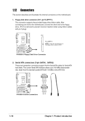
... NOTE: Orient the red markings on the motherboard. 1. After connecting one end to the motherboard, connect the other end to the floppy drive. (Pin 5 is removed to PIN 1. P4V800-X Floppy Disk Drive Connector 2. The current Serial ATA interface allows up to...). SATA1 GND RSATA_RXP1 RSATA_RXN1 GND RSATA_TXN1 RSATA_TXP1 GND P4V800-X SATA2 GND RSATA_RXP2 RSATA_RXN2 GND RSATA_TXN2 RSATA_TXP2 GND P4V800-X SATA Connectors 1-18 Chapter 1: Product introduction Floppy disk drive connector (34-1 pin FLOPPY1) This connector supports the provided floppy drive ribbon cable. Serial ATA connectors...
... NOTE: Orient the red markings on the motherboard. 1. After connecting one end to the motherboard, connect the other end to the floppy drive. (Pin 5 is removed to PIN 1. P4V800-X Floppy Disk Drive Connector 2. The current Serial ATA interface allows up to...). SATA1 GND RSATA_RXP1 RSATA_RXN1 GND RSATA_TXN1 RSATA_TXP1 GND P4V800-X SATA2 GND RSATA_RXP2 RSATA_RXN2 GND RSATA_TXN2 RSATA_TXP2 GND P4V800-X SATA Connectors 1-18 Chapter 1: Product introduction Floppy disk drive connector (34-1 pin FLOPPY1) This connector supports the provided floppy drive ribbon cable. Serial ATA connectors...
P4V800-X User Manual
Page 29
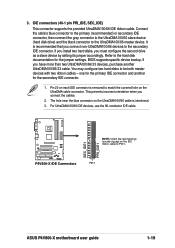
... near the blue connector on the UltraDMA100/66 cable is removed to the hard disk documentation for the secondary IDE connector. 1. P4V800-X P4V800-X IDE Connectors SEC_IDE1 PRI_IDE1 NOTE: Orient the red markings (usually zigzag) on each IDE connector is intentional. 3. IDE connectors ...(40-1 pin PRI_IDE, SEC_IDE) This connector supports the provided UltraDMA100/66 IDE ribbon cable. This prevents incorrect orientation when you must configure the second drive as a slave device by setting its jumper accordingly. PIN 1 ASUS P4V800-X motherboard user guide 1-19 Refer to match the ...
... near the blue connector on the UltraDMA100/66 cable is removed to the hard disk documentation for the secondary IDE connector. 1. P4V800-X P4V800-X IDE Connectors SEC_IDE1 PRI_IDE1 NOTE: Orient the red markings (usually zigzag) on each IDE connector is intentional. 3. IDE connectors ...(40-1 pin PRI_IDE, SEC_IDE) This connector supports the provided UltraDMA100/66 IDE ribbon cable. This prevents incorrect orientation when you must configure the second drive as a slave device by setting its jumper accordingly. PIN 1 ASUS P4V800-X motherboard user guide 1-19 Refer to match the ...

P4V800-X User Manual
Page 30
...black wire of each cable matches the ground pin of the connector. CPU and chassis fan connectors (3-pin CPU_FAN1, CHA_FAN1) The fan connectors support cooling fans of 350mA~740mA (8.88W max.) or a total of sufficient air flow within the system may experience difficulty powering up if ...8A on the +12V lead and at +12V. The system may become unstable and may damage the motherboard components. Connect the fan cables to the fan connectors. The minimum recommended wattage is inadequate. ® P4V800-X ATXPWR1 ATX12V1 Pin 1 +12.0VDC +5VSB PWR_OK COM +5.0VDC COM +5.0VDC COM +3.3VDC +3....
...black wire of each cable matches the ground pin of the connector. CPU and chassis fan connectors (3-pin CPU_FAN1, CHA_FAN1) The fan connectors support cooling fans of 350mA~740mA (8.88W max.) or a total of sufficient air flow within the system may experience difficulty powering up if ...8A on the +12V lead and at +12V. The system may become unstable and may damage the motherboard components. Connect the fan cables to the fan connectors. The minimum recommended wattage is inadequate. ® P4V800-X ATXPWR1 ATX12V1 Pin 1 +12.0VDC +5VSB PWR_OK COM +5.0VDC COM +5.0VDC COM +3.3VDC +3....
P4V800-X User Manual
Page 31
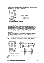
The USB header complies with USB 2.0 specification that support the next generation USB peripherals such as a CD-ROM, TV tuner, or MPEG card. ASUS P4V800-X motherboard user guide USB+5V USB_P5USB_P5+ GND 1-21 Connect an optional USB 2.0/GAME module to 480 Mbps connection speed. Internal audio connectors (4-pin CD1, AUX1) These ...
The USB header complies with USB 2.0 specification that support the next generation USB peripherals such as a CD-ROM, TV tuner, or MPEG card. ASUS P4V800-X motherboard user guide USB+5V USB_P5USB_P5+ GND 1-21 Connect an optional USB 2.0/GAME module to 480 Mbps connection speed. Internal audio connectors (4-pin CD1, AUX1) These ...
P4V800-X User Manual
Page 36
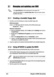
... Programs icon from the support CD to the bootable floppy disk that contains the BIOS file. 3. Copy the AFUDOS.EXE utility from the Control Panel window. d. Follow the succeeding screen instructions to a bootable floppy disk. Copy the original (or the latest) motherboard BIOS to the bootable ...1.44 MB floppy disk when prompted. Save the BIOS file to complete the process. 2. Visit the ASUS website (www.asus.com) to download the latest BIOS file for this motherboard is in the support CD. Write down the BIOS file name to a piece of the following to create a bootable floppy...
... Programs icon from the support CD to the bootable floppy disk that contains the BIOS file. 3. Copy the AFUDOS.EXE utility from the Control Panel window. d. Follow the succeeding screen instructions to a bootable floppy disk. Copy the original (or the latest) motherboard BIOS to the bootable ...1.44 MB floppy disk when prompted. Save the BIOS file to complete the process. 2. Visit the ASUS website (www.asus.com) to download the latest BIOS file for this motherboard is in the support CD. Write down the BIOS file name to a piece of the following to create a bootable floppy...
P4V800-X User Manual
Page 40
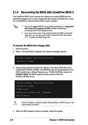
...tool allows you to restore BIOS from the motherboard support CD, or from a floppy disk that contains the motherboard BIOS (P4V800-X.ROM) before proceeding with the motherboard or a floppy disk that contains the BIOS file, in case the current BIOS on the motherboard fails or gets corrupted. 1. If you have...the support CD that came with the BIOS update process. 2. Bad BIOS checksum. Reading file "p4v800-x.rom". DO NOT shutdown or reset the system while updating the BIOS! When the BIOS update process is detected, the following message appears. To recover the BIOS from the ASUS ...
...tool allows you to restore BIOS from the motherboard support CD, or from a floppy disk that contains the motherboard BIOS (P4V800-X.ROM) before proceeding with the motherboard or a floppy disk that contains the BIOS file, in case the current BIOS on the motherboard fails or gets corrupted. 1. If you have...the support CD that came with the BIOS update process. 2. Bad BIOS checksum. Reading file "p4v800-x.rom". DO NOT shutdown or reset the system while updating the BIOS! When the BIOS update process is detected, the following message appears. To recover the BIOS from the ASUS ...
P4V800-X User Manual
Page 41
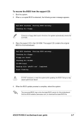
Starting BIOS recovery... The support CD contains the original BIOS for this motherboard. Checking for floppy... DO NOT shutdown or reset the system while updating the BIOS! Doing so may not be the latest BIOS version for floppy... ASUS P4V800-X motherboard user guide 2-7 Boot the...4. To recover the BIOS from the support CD: 1. Bad BIOS checksum. Visit the ASUS website (www.asus.com) to download the latest BIOS file. Checking for CD-ROM... Checking for this motherboard. Completed. Start flashing... Place the support CD in the drive, the system automatically...
Starting BIOS recovery... The support CD contains the original BIOS for this motherboard. Checking for floppy... DO NOT shutdown or reset the system while updating the BIOS! Doing so may not be the latest BIOS version for floppy... ASUS P4V800-X motherboard user guide 2-7 Boot the...4. To recover the BIOS from the support CD: 1. Bad BIOS checksum. Visit the ASUS website (www.asus.com) to download the latest BIOS file. Checking for CD-ROM... Checking for this motherboard. Completed. Start flashing... Place the support CD in the drive, the system automatically...
P4V800-X User Manual
Page 42
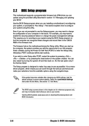
...RAM of your computer in section "2.1 Managing and updating your selections from the available options using the navigation keys. Visit the ASUS website (www.asus.com) to enter the Setup utility. Press during the Power-On Self Test (POST) to download the latest product and ... reset button on the motherboard stores the Setup utility. Even if you are installing a motherboard, reconfiguring your system using the BIOS Setup program so that you can update using the provided utility described in the future. 2.2 BIOS Setup program This motherboard supports a programmable firmware hub ...
...RAM of your computer in section "2.1 Managing and updating your selections from the available options using the navigation keys. Visit the ASUS website (www.asus.com) to enter the Setup utility. Press during the Power-On Self Test (POST) to download the latest product and ... reset button on the motherboard stores the Setup utility. Even if you are installing a motherboard, reconfiguring your system using the BIOS Setup program so that you can update using the provided utility described in the future. 2.2 BIOS Setup program This motherboard supports a programmable firmware hub ...
P4V800-X User Manual
Page 49
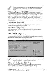
...(CPU) operating voltage. USB Configuration Module Version : 2.22.4-5.3 USB Devices Enabled : None USB 1.1 Ports Configuration USB 2.0 Ports Enable Legacy USB Support USB 2.0 Controller Mode [8 USB Ports] [Enabled] [Auto] [HiSpeed] USB Mass Storage Device Configuration Enables USB host controllers. USB 1.1 Ports ... Overclock Tuner item. Configuration options: [Disabled] [USB 2 Ports] [USB 4 Ports] [USB 6 Ports] [USB 8 Ports] ASUS P4V800-X motherboard user guide 2-15 Change Option F1 General Help F10 Save and Exit ESC Exit The Module Version and USB Devices Enabled items show the...
...(CPU) operating voltage. USB Configuration Module Version : 2.22.4-5.3 USB Devices Enabled : None USB 1.1 Ports Configuration USB 2.0 Ports Enable Legacy USB Support USB 2.0 Controller Mode [8 USB Ports] [Enabled] [Auto] [HiSpeed] USB Mass Storage Device Configuration Enables USB host controllers. USB 1.1 Ports ... Overclock Tuner item. Configuration options: [Disabled] [USB 2 Ports] [USB 4 Ports] [USB 6 Ports] [USB 8 Ports] ASUS P4V800-X motherboard user guide 2-15 Change Option F1 General Help F10 Save and Exit ESC Exit The Module Version and USB Devices Enabled items show the...
P4V800-X User Manual
Page 66
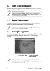
...motherboard settings and hardware options vary, use the setup procedures presented in this chapter for more information If Autorun is enabled in your hardware. Visit the ASUS website for updates. 3.2.1 Running the support CD To begin using the support CD, simply insert the CD into your computer. The contents of the support... an item to install Click an icon to change at any time without notice. 3.1 Install an operating system This motherboard supports Windows 98SE/ME/2000/XP operating system (OS). Always install the latest OS version and corresponding updates so you can...
...motherboard settings and hardware options vary, use the setup procedures presented in this chapter for more information If Autorun is enabled in your hardware. Visit the ASUS website for updates. 3.2.1 Running the support CD To begin using the support CD, simply insert the CD into your computer. The contents of the support... an item to install Click an icon to change at any time without notice. 3.1 Install an operating system This motherboard supports Windows 98SE/ME/2000/XP operating system (OS). Always install the latest OS version and corresponding updates so you can...
P4V800-X User Manual
Page 67
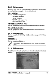
...100Mbps Fast Ethernet driver to activate the devices. VIA ATAPI vendor support driver - USB 2.0 Driver This item installs the USB 2.0 driver. ASUS P4V800-X motherboard user guide 3-3 Install the necessary drivers to support 10/100 Mbps networking. VIA AGP VxD driver - For Windows ...VIA RAID Controller driver This item installs the VIA RAID controller driver and application to support USB 2.0. 3.2.3 Utilities menu The Utilities menu shows the applications and other software that the motherboard supports. VIA 4 in 1 drivers This item installs the following drivers: - 3.2.2 ...
...100Mbps Fast Ethernet driver to activate the devices. VIA ATAPI vendor support driver - USB 2.0 Driver This item installs the USB 2.0 driver. ASUS P4V800-X motherboard user guide 3-3 Install the necessary drivers to support 10/100 Mbps networking. VIA AGP VxD driver - For Windows ...VIA RAID Controller driver This item installs the VIA RAID controller driver and application to support USB 2.0. 3.2.3 Utilities menu The Utilities menu shows the applications and other software that the motherboard supports. VIA 4 in 1 drivers This item installs the following drivers: - 3.2.2 ...
P4V800-X User Manual
Page 69
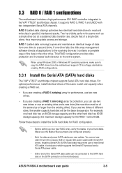
... to a floppy disk before creating RAID configurations. 3.3.1 Install the Serial ATA (SATA) hard disks The VIA® VT8237 southbridge chipset supports Serial ATA hard disk drives. For example, one drive to read and write data in the VIA® VT8237 southbridge chipset. RAID .... RAID 0 (called data mirroring) copies and maintains an identical image of data from the motherboard support CD to the entire system. If you can be the base storage size. ASUS P4V800-X motherboard user guide 3-5 Make sure the Master/Slave jumpers are configured properly. • Both the ...
... to a floppy disk before creating RAID configurations. 3.3.1 Install the Serial ATA (SATA) hard disks The VIA® VT8237 southbridge chipset supports Serial ATA hard disk drives. For example, one drive to read and write data in the VIA® VT8237 southbridge chipset. RAID .... RAID 0 (called data mirroring) copies and maintains an identical image of data from the motherboard support CD to the entire system. If you can be the base storage size. ASUS P4V800-X motherboard user guide 3-5 Make sure the Master/Slave jumpers are configured properly. • Both the ...


