Motherboard DIY Troubleshooting Guide
Page 35
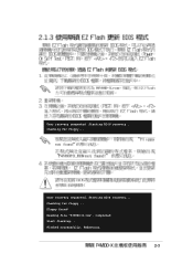
Starting BIOS recovery... Reading file "P4V800-X.rom". Starting BIOS recovery... Checking for floppy... Completed. User recovery requested. Rebooting. 2-3 Floppy found! Flashed successfully. Start flashing... User recovery requested. Checking for floppy...
Starting BIOS recovery... Reading file "P4V800-X.rom". Starting BIOS recovery... Checking for floppy... Completed. User recovery requested. Rebooting. 2-3 Floppy found! Flashed successfully. Start flashing... User recovery requested. Checking for floppy...
Motherboard DIY Troubleshooting Guide
Page 36
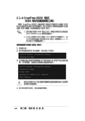
Floppy found! Reading file "P4V800-X.rom". Starting BIOS recovery... Completed. Bad BIOS checksum. Start flashing... 2-4 Checking for floppy... Bad BIOS checksum. Checking for floppy... Starting BIOS recovery...
Floppy found! Reading file "P4V800-X.rom". Starting BIOS recovery... Completed. Bad BIOS checksum. Start flashing... 2-4 Checking for floppy... Bad BIOS checksum. Checking for floppy... Starting BIOS recovery...
Motherboard DIY Troubleshooting Guide
Page 37
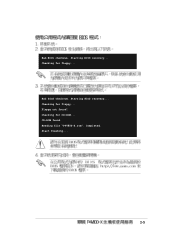
Checking for CD-ROM... Floppy not found . Starting BIOS recovery... Bad BIOS checksum. Bad BIOS checksum. Checking for floppy... CD-ROM found ! Start flashing... 2-5 Checking for floppy... Reading file "P4V800-X.rom". Completed. Starting BIOS recovery...
Checking for CD-ROM... Floppy not found . Starting BIOS recovery... Bad BIOS checksum. Bad BIOS checksum. Checking for floppy... CD-ROM found ! Start flashing... 2-5 Checking for floppy... Reading file "P4V800-X.rom". Completed. Starting BIOS recovery...
Motherboard DIY Troubleshooting Guide
Page 43
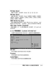
AMI BIOS Version : 08.00.09 Build Date : 07/07/03 Processor Type Speed Count : Intel(R) Pentium(R) 4 CPU 1500MHz : 1500 MHz : 1 System Memory Size : 256MB Select Screen Select Item +- Change Option F1 General Help F10 Save and Exit ESC Exit 2-11
AMI BIOS Version : 08.00.09 Build Date : 07/07/03 Processor Type Speed Count : Intel(R) Pentium(R) 4 CPU 1500MHz : 1500 MHz : 1 System Memory Size : 256MB Select Screen Select Item +- Change Option F1 General Help F10 Save and Exit ESC Exit 2-11
Motherboard DIY Troubleshooting Guide
Page 53
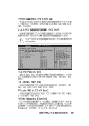
...] [64] [Yes] [Disabled] [Enabled] IRQ3 IRQ4 IRQ5 IRQ7 IRQ9 IRQ10 IRQ11 IRQ14 IRQ15 [Available] [Available] [Available] [Available] [Available] [Available] [Available] [Available] [Available] NO: Lets the bIOS configure all the devices in the system.
...] [64] [Yes] [Disabled] [Enabled] IRQ3 IRQ4 IRQ5 IRQ7 IRQ9 IRQ10 IRQ11 IRQ14 IRQ15 [Available] [Available] [Available] [Available] [Available] [Available] [Available] [Available] [Available] NO: Lets the bIOS configure all the devices in the system.
Motherboard DIY Troubleshooting Guide
Page 60
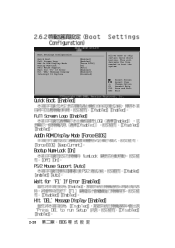
This will decrease the time needed to skip certain tests while booting. Change Option F1 General Help F10 Save and Exit ESC Exit 2-28 Boot Settings Configuration Quick Boot Full Screen Logo Add On ROM Display Mode Bootup Num-Lock PS/2 Mouse Support Wait for 'F1' If Error Hit 'DEL' Message Display Interrupt 19 Capture [Enabled] [Enabled] [Force BIOS] [On] [Auto] [Enabled] [Enabled]\ [Disabled] Allows BIOS to boot the system. Select Screen Select Item +-
This will decrease the time needed to skip certain tests while booting. Change Option F1 General Help F10 Save and Exit ESC Exit 2-28 Boot Settings Configuration Quick Boot Full Screen Logo Add On ROM Display Mode Bootup Num-Lock PS/2 Mouse Support Wait for 'F1' If Error Hit 'DEL' Message Display Interrupt 19 Capture [Enabled] [Enabled] [Force BIOS] [On] [Auto] [Enabled] [Enabled]\ [Disabled] Allows BIOS to boot the system. Select Screen Select Item +-
Motherboard DIY Troubleshooting Guide
Page 69
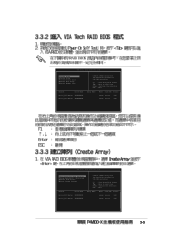
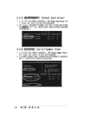
RAID BIOS Ver 1.XX Create Array Delete Array Create/Delete Spare Select Boot Array Serial Number View Channel Drive Name Serial_Ch0 Master XXXXXXXXXX Serial_Ch1 Master XXXXXXXXXX Create a ... next item Enter: Confirme the selection ESC : Exit Array Name Mode Size(GB) Status xxxxx xxx.xx Hdd xxxxx xxx.xx Hdd VIA Tech. RAID BIOS Ver 1.xx Auto Setup For Data Security Array Mode RAID 1 (Mirroring) Select Disk Drives Start Create Process Create a RAID array with the hard disk attached...
RAID BIOS Ver 1.XX Create Array Delete Array Create/Delete Spare Select Boot Array Serial Number View Channel Drive Name Serial_Ch0 Master XXXXXXXXXX Serial_Ch1 Master XXXXXXXXXX Create a ... next item Enter: Confirme the selection ESC : Exit Array Name Mode Size(GB) Status xxxxx xxx.xx Hdd xxxxx xxx.xx Hdd VIA Tech. RAID BIOS Ver 1.xx Auto Setup For Data Security Array Mode RAID 1 (Mirroring) Select Disk Drives Start Create Process Create a RAID array with the hard disk attached...
Motherboard DIY Troubleshooting Guide
Page 72
RAID BIOS Ver 1.xx Create Array Delete Array Create/Delete Spare Select Boot Array Serial Number View Channel Drive Name Serial_Ch0 Master XXXXXXXXXX Serial_Ch1 Master XXXXXXXXXX Create a ...
RAID BIOS Ver 1.xx Create Array Delete Array Create/Delete Spare Select Boot Array Serial Number View Channel Drive Name Serial_Ch0 Master XXXXXXXXXX Serial_Ch1 Master XXXXXXXXXX Create a ...
P4V800-X User Manual
Page 3
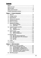
Features Contents Notices v Safety information vi About this guide vii ASUS contact information viii P4V800-X specifications summary ix Chapter 1: Product introduction 1.1 Welcome 1-2 1.2 Package contents 1-2 1.3 Special features 1-2 1.4 Motherboard components 1-4 ...1-18 Chapter 2: BIOS information 2.1 Managing and updating your BIOS 2-2 2.1.1 Creating a bootable floppy disk 2-2 2.1.2 Using AFUDOS to update the BIOS 2-2 2.1.3 Using AFUDOS to copy BIOS from PC 2-4 2.1.4 Using ASUS EZ Flash to update the BIOS 2-5 2.1.5 Using ASUS CrashFree BIOS 2 2-6 2.2 BIOS Setup program 2-8 iii
Features Contents Notices v Safety information vi About this guide vii ASUS contact information viii P4V800-X specifications summary ix Chapter 1: Product introduction 1.1 Welcome 1-2 1.2 Package contents 1-2 1.3 Special features 1-2 1.4 Motherboard components 1-4 ...1-18 Chapter 2: BIOS information 2.1 Managing and updating your BIOS 2-2 2.1.1 Creating a bootable floppy disk 2-2 2.1.2 Using AFUDOS to update the BIOS 2-2 2.1.3 Using AFUDOS to copy BIOS from PC 2-4 2.1.4 Using ASUS EZ Flash to update the BIOS 2-5 2.1.5 Using ASUS CrashFree BIOS 2 2-6 2.2 BIOS Setup program 2-8 iii
P4V800-X User Manual
Page 4
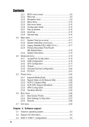
Safeguards Contents 2.2.1 2.2.2 2.2.3 2.2.4 2.2.5 2.2.6 2.2.7 2.2.8 2.2.9 BIOS menu screen 2-9 Menu bar 2-9 Navigation keys 2-9 Menu items 2-10 Sub-menu items 2-10 Configuration fields 2-10 Pop-up window 2-10 Scroll bar 2-10 General help 2-...
Safeguards Contents 2.2.1 2.2.2 2.2.3 2.2.4 2.2.5 2.2.6 2.2.7 2.2.8 2.2.9 BIOS menu screen 2-9 Menu bar 2-9 Navigation keys 2-9 Menu items 2-10 Sub-menu items 2-10 Configuration fields 2-10 Pop-up window 2-10 Scroll bar 2-10 General help 2-...
P4V800-X User Manual
Page 9
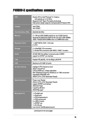
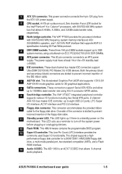
P4V800-X specifications summary CPU Chipset Front Side Bus (FSB) Memory Expansion slots Storage Audio LAN USB AI Overclocking Special features Back panel I/O Socket 478 for Intel&#... CPU and Memory voltage adjustable SFS (Stepless Frequency Selection) at 1 MHz increment Adjustable FSB/DDR ratio ASUS C.P.R. (CPU Parameter Recall) Power Loss Restart ASUS C.P.R. (CPU Parameter Recall) support S/PDIF out interface ASUS EZ Flash CrashFree BIOS 2 ASUS MyLogo2 1 x Parallel port 1 x Serial port 1 x PS/2 keyboard port 1 x PS/2 mouse port 4 x USB 2.0 ports 1 x S/PDIF out 1 x RJ-45 port...
P4V800-X specifications summary CPU Chipset Front Side Bus (FSB) Memory Expansion slots Storage Audio LAN USB AI Overclocking Special features Back panel I/O Socket 478 for Intel&#... CPU and Memory voltage adjustable SFS (Stepless Frequency Selection) at 1 MHz increment Adjustable FSB/DDR ratio ASUS C.P.R. (CPU Parameter Recall) Power Loss Restart ASUS C.P.R. (CPU Parameter Recall) support S/PDIF out interface ASUS EZ Flash CrashFree BIOS 2 ASUS MyLogo2 1 x Parallel port 1 x Serial port 1 x PS/2 keyboard port 1 x PS/2 mouse port 4 x USB 2.0 ports 1 x S/PDIF out 1 x RJ-45 port...

P4V800-X User Manual
Page 10
P4V800-X specifications summary Internal I/O BIOS features Industry standard Manageability Power Requirement Support CD contents Form Factor 2 x USB 2.0 connector for 4 additional USB ports CPU/Chassis fan connectors 20-pin/4-pin ATX 12V power connectors CD/AUX connectors Game/MIDI connector 10-1 pin front panel connector 4Mb Flash ROM, AMI BIOS, ACPI, PnP, DMI2.0, ASUS... EZ Flash, ASUS MyLogo2 PCI 2.2, USB 2.0/1.1 DMI 2.0, WOL/WOR by PME, chassis intrusion ATX power supply ...
P4V800-X specifications summary Internal I/O BIOS features Industry standard Manageability Power Requirement Support CD contents Form Factor 2 x USB 2.0 connector for 4 additional USB ports CPU/Chassis fan connectors 20-pin/4-pin ATX 12V power connectors CD/AUX connectors Game/MIDI connector 10-1 pin front panel connector 4Mb Flash ROM, AMI BIOS, ACPI, PnP, DMI2.0, ASUS... EZ Flash, ASUS MyLogo2 PCI 2.2, USB 2.0/1.1 DMI 2.0, WOL/WOR by PME, chassis intrusion ATX power supply ...
P4V800-X User Manual
Page 13
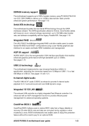
...or recovery CD when BIOS code and data are corrupted during upgrade or when invaded by a virus. See pages 1-6 and 1-21. 6-channel digital audio The ADI 1980 AC'97 audio CODEC is a highly integrated Fast Ethernet controller. ASUS P4V800-X motherboard user guide 1-3 ASUS motherboards now enable ...rate, and software compatibility with an ACPI management function to provide efficient power management for advanced operating systems. CrashFree BIOS 2 CrashFree BIOS 2 allows users to restore BIOS data from 12 Mbps on USB 1.1 to a fast 480 Mbps on USB 2.0. Serial ATA technology The motherboard ...
...or recovery CD when BIOS code and data are corrupted during upgrade or when invaded by a virus. See pages 1-6 and 1-21. 6-channel digital audio The ADI 1980 AC'97 audio CODEC is a highly integrated Fast Ethernet controller. ASUS P4V800-X motherboard user guide 1-3 ASUS motherboards now enable ...rate, and software compatibility with an ACPI management function to provide efficient power management for advanced operating systems. CrashFree BIOS 2 CrashFree BIOS 2 allows users to restore BIOS data from 12 Mbps on USB 1.1 to a fast 480 Mbps on USB 2.0. Serial ATA technology The motherboard ...
P4V800-X User Manual
Page 15
... of the floppy disk cable. 11 Standby power LED. This LED acts as a reminder to an ATX power supply. This 4Mb firmware contains the programmable BIOS program. 13 Super I /O functionality. This power connector connects the 4-pin 12V plug from the ATX 12V power supply. 2 CPU socket. The VIA® PT800 provides... dual-channel bus master IDE connectors support Ultra DMA133/100/66, PIO Modes 3 & 4 IDE devices. One side of the IDE ribbon cable. 7 AGP 8X slot. ASUS P4V800-X motherboard user guide 1-5
... of the floppy disk cable. 11 Standby power LED. This LED acts as a reminder to an ATX power supply. This 4Mb firmware contains the programmable BIOS program. 13 Super I /O functionality. This power connector connects the 4-pin 12V plug from the ATX 12V power supply. 2 CPU socket. The VIA® PT800 provides... dual-channel bus master IDE connectors support Ultra DMA133/100/66, PIO Modes 3 & 4 IDE devices. One side of the IDE ribbon cable. 7 AGP 8X slot. ASUS P4V800-X motherboard user guide 1-5
P4V800-X User Manual
Page 24
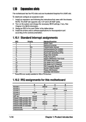
...2 - - Onboard USB controller HC2 - shared - - Onboard LAN shared - - - Turn on the system and change the necessary BIOS settings, if any. Install the drivers and/or software applications for the expansion card according to the card documentation. 1.10.1 Standard interrupt assignments...9 Primary IDE Channel 15* 10 Secondary IDE Channel * These IRQs are usually available for ISA or PCI devices. 1.10.2 IRQ assignments for BIOS information. 3. PCI slot 5 - Onboard USB controller HC3 - Onboard USB 2.0 controller - - Onboard USB controller HC1 shared - - -...
...2 - - Onboard USB controller HC2 - shared - - Onboard LAN shared - - - Turn on the system and change the necessary BIOS settings, if any. Install the drivers and/or software applications for the expansion card according to the card documentation. 1.10.1 Standard interrupt assignments...9 Primary IDE Channel 15* 10 Secondary IDE Channel * These IRQs are usually available for ISA or PCI devices. 1.10.2 IRQ assignments for BIOS information. 3. PCI slot 5 - Onboard USB controller HC3 - Onboard USB 2.0 controller - - Onboard USB controller HC1 shared - - -...
P4V800-X User Manual
Page 26
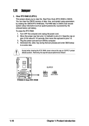
...the CMOS memory of date, time, and system setup parameters by the onboard button cell battery. Removing the cap will cause system boot failure! P4V800-X P4V800-X Clear RTC RAM CLRTC1 12 Normal (Default) 23 Clear CMOS 1-16 Chapter 1: Product introduction Keep the cap on CLRTC1 jumper default position....data. 1.11 Jumper 1. Turn OFF the computer and unplug the power cord. 2. Hold down the key during the boot process and enter BIOS setup to clear the Real Time Clock (RTC) RAM in CMOS, that include system setup information such as system passwords, is powered by erasing...
...the CMOS memory of date, time, and system setup parameters by the onboard button cell battery. Removing the cap will cause system boot failure! P4V800-X P4V800-X Clear RTC RAM CLRTC1 12 Normal (Default) 23 Clear CMOS 1-16 Chapter 1: Product introduction Keep the cap on CLRTC1 jumper default position....data. 1.11 Jumper 1. Turn OFF the computer and unplug the power cord. 2. Hold down the key during the boot process and enter BIOS setup to clear the Real Time Clock (RTC) RAM in CMOS, that include system setup information such as system passwords, is powered by erasing...
P4V800-X User Manual
Page 29
If you install two hard disks, you have more than two UltraDMA100/66/33 devices, purchase another for the jumper settings. BIOS supports specific device bootup. Pin 20 on the UltraDMA cable connector. one for the primary IDE connector and another UltraDMA100/66/33 cable....connector to the UltraDMA100/66 slave device (hard disk drive) and the black connector to be both master devices with two ribbon cables - PIN 1 ASUS P4V800-X motherboard user guide 1-19 If you must configure the second drive as a slave device by setting its jumper accordingly. It is removed to the...
If you install two hard disks, you have more than two UltraDMA100/66/33 devices, purchase another for the jumper settings. BIOS supports specific device bootup. Pin 20 on the UltraDMA cable connector. one for the primary IDE connector and another UltraDMA100/66/33 cable....connector to the UltraDMA100/66 slave device (hard disk drive) and the black connector to be both master devices with two ribbon cables - PIN 1 ASUS P4V800-X motherboard user guide 1-19 If you must configure the second drive as a slave device by setting its jumper accordingly. It is removed to the...
P4V800-X User Manual
Page 34
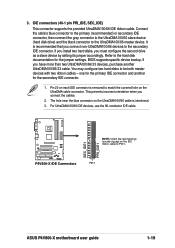
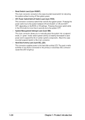
... a switch that controls the system power. Pressing the power switch turns the system between ON and SLEEP, or ON and SOFT OFF, depending on the BIOS or OS settings. Attach the casemounted suspend switch to this LED to light up. 1-24 Chapter 1: Product introduction
... a switch that controls the system power. Pressing the power switch turns the system between ON and SLEEP, or ON and SOFT OFF, depending on the BIOS or OS settings. Attach the casemounted suspend switch to this LED to light up. 1-24 Chapter 1: Product introduction
P4V800-X User Manual
Page 35
Detailed descriptions of the BIOS parameters are also provided. BIOS information Chapter 2 This chapter tells how to change system settings through the BIOS Setup menus.
Detailed descriptions of the BIOS parameters are also provided. BIOS information Chapter 2 This chapter tells how to change system settings through the BIOS Setup menus.
P4V800-X User Manual
Page 36
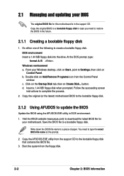
...2. Double-click on Add/Remove Programs icon from the floppy disk. 2-2 Chapter 2: BIOS information button. c. Insert a 1.44 MB floppy disk when prompted. Visit the ASUS website (www.asus.com) to download the latest BIOS file for this motherboard is in the support CD. Copy the AFUDOS.EXE utility from ...the support CD to a bootable floppy disk. Do either one of paper. Save the BIOS file to the bootable ...
...2. Double-click on Add/Remove Programs icon from the floppy disk. 2-2 Chapter 2: BIOS information button. c. Insert a 1.44 MB floppy disk when prompted. Visit the ASUS website (www.asus.com) to download the latest BIOS file for this motherboard is in the support CD. Copy the AFUDOS.EXE utility from ...the support CD to a bootable floppy disk. Do either one of paper. Save the BIOS file to the bootable ...


