User Manual
Page 4
HARDWARE SETUP 14 3.1 P4T-F Motherboard Layout 14 3.2 Layout Contents 15 3.3 Hardware Setup Procedure 16 3.4 Motherboard Settings 17 3.5 System Memory 23 3.5.1 CPU Installation 25 3.5 Central Processing Unit (CPU 25 3.5.2 CPU Heatsink Retention Module Installation 26 3.6 Expansion Cards 29 ...56 4.4 Advanced Menu 58 4.4.1 Chip Configuration 61 4.4.2 I/O Device Configuration 63 4.4.3 PCI Configuration 65 4.4.4 Shadow Configuration 67 4.5 Power Menu 68 4 ASUS P4T-F User's Manual INTRODUCTION 7 1.1 How This Manual Is Organized 7 1.2 Item Checklist 7 2. FEATURES 8 2.1 The...
HARDWARE SETUP 14 3.1 P4T-F Motherboard Layout 14 3.2 Layout Contents 15 3.3 Hardware Setup Procedure 16 3.4 Motherboard Settings 17 3.5 System Memory 23 3.5.1 CPU Installation 25 3.5 Central Processing Unit (CPU 25 3.5.2 CPU Heatsink Retention Module Installation 26 3.6 Expansion Cards 29 ...56 4.4 Advanced Menu 58 4.4.1 Chip Configuration 61 4.4.2 I/O Device Configuration 63 4.4.3 PCI Configuration 65 4.4.4 Shadow Configuration 67 4.5 Power Menu 68 4 ASUS P4T-F User's Manual INTRODUCTION 7 1.1 How This Manual Is Organized 7 1.2 Item Checklist 7 2. FEATURES 8 2.1 The...

User Manual
Page 8
... switches are necessary to 1.8 GHz and higher. • Intel 850 Chipset: Features the Intel® 850 chipset (82850 Tehama Memory Controller Hub, I /O Controller Hub 2 (82801 ICH2) features support for exceptiona peripheral connectivity options. 8 ASUS P4T-F User's Manual 2. Supports UltraDMA/100, UltraDMA/66, UltraDMA/33, PIO Modes 3 & 4 and Bus Master IDE DMA Mode 2, and...
... switches are necessary to 1.8 GHz and higher. • Intel 850 Chipset: Features the Intel® 850 chipset (82850 Tehama Memory Controller Hub, I /O Controller Hub 2 (82801 ICH2) features support for exceptiona peripheral connectivity options. 8 ASUS P4T-F User's Manual 2. Supports UltraDMA/100, UltraDMA/66, UltraDMA/33, PIO Modes 3 & 4 and Bus Master IDE DMA Mode 2, and...
User Manual
Page 9
... voltages, temperatures, and fan status through the onboard hardware and the bundled ASUS PC Probe or Intel LDCM software. • Legacy Free: Provides five 32-bit PCI (PCI 2.2 compliant) with this 6 tooth connector. ASUS P4T-F User's Manual 9 All PCI slots can also be directed from PCI... master bus to the memory and processor. • Onboard LED: Signals AC power is okay. • Desktop Management Interface (DMI...
... voltages, temperatures, and fan status through the onboard hardware and the bundled ASUS PC Probe or Intel LDCM software. • Legacy Free: Provides five 32-bit PCI (PCI 2.2 compliant) with this 6 tooth connector. ASUS P4T-F User's Manual 9 All PCI slots can also be directed from PCI... master bus to the memory and processor. • Onboard LED: Signals AC power is okay. • Desktop Management Interface (DMI...
User Manual
Page 10
...UltraDMA/33 (IDE DMA Mode 2), PIO Modes 3 & 4, and supports Enhanced IDE devices, such as required by PC 99. 10 ASUS P4T-F User's Manual 2. FEATURES Specifications 2. ACPI provides more Energy Saving Features for Windows 95/NT and later. The new PC 99 requirements ... of 0.8GB/s, MCH dual channel Rambus DRAMs can be enabled.) • RDRAM Optimized Performance: This motherboard supports Rambus Dynamic Random Access Memory (RDRAM). FEATURES 2.1.3 Performance Features • High-Speed Data Transfer Interface: Onboard IDE Bus Master controller with two connectors that you do...
...UltraDMA/33 (IDE DMA Mode 2), PIO Modes 3 & 4, and supports Enhanced IDE devices, such as required by PC 99. 10 ASUS P4T-F User's Manual 2. FEATURES Specifications 2. ACPI provides more Energy Saving Features for Windows 95/NT and later. The new PC 99 requirements ... of 0.8GB/s, MCH dual channel Rambus DRAMs can be enabled.) • RDRAM Optimized Performance: This motherboard supports Rambus Dynamic Random Access Memory (RDRAM). FEATURES 2.1.3 Performance Features • High-Speed Data Transfer Interface: Onboard IDE Bus Master controller with two connectors that you do...
User Manual
Page 11
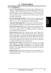
... (ie.: Suspend or Sleep) button or as Windows 98/ Millenium, and Windows NT/2000, require much more memory and hard drive space to enable Pentium 4 processors auto throttling function. Voltage specifications are set for more information) button. The onboard ...will warn the user before the system resources are monitored to ensure stable current to be powered ON using your keyboard or mouse click. ASUS P4T-F User's Manual 11 FEATURES Intelligence 2. FEATURES 2.1.4 Intelligence • Auto CPU Throttling Function: Incorporated into this motherboard supports processor thermal ...
... (ie.: Suspend or Sleep) button or as Windows 98/ Millenium, and Windows NT/2000, require much more memory and hard drive space to enable Pentium 4 processors auto throttling function. Voltage specifications are set for more information) button. The onboard ...will warn the user before the system resources are monitored to ensure stable current to be powered ON using your keyboard or mouse click. ASUS P4T-F User's Manual 11 FEATURES Intelligence 2. FEATURES 2.1.4 Intelligence • Auto CPU Throttling Function: Incorporated into this motherboard supports processor thermal ...
User Manual
Page 12
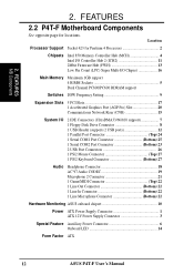
...for locations. FEATURES 2.2 P4T-F Motherboard Components See opposite page for Pentium 4 Processors 2 Chipsets Intel 850 Memory Controller Hub (MCH 4 Intel I/O Controller Hub 2 (ICH2 11 2Mbit Firmware Hub (FWH 13 Low Pin Count (LPC) Super Multi-I/O Chipset 16 Main Memory Maximum 1GB support 4 RIMM...Top) 22 1 Line Out Connector Bottom) 22 1 Line In Connector Bottom) 22 1 Line Microphone Connector Bottom) 22 Hardware Monitoring ASUS onboard chipset 10 Power ATX Power Supply Connector 1 ATX 12V Power Supply Connector 3 Special Feature Auxillary Power Connector 6 Onboard LED ...
...for locations. FEATURES 2.2 P4T-F Motherboard Components See opposite page for Pentium 4 Processors 2 Chipsets Intel 850 Memory Controller Hub (MCH 4 Intel I/O Controller Hub 2 (ICH2 11 2Mbit Firmware Hub (FWH 13 Low Pin Count (LPC) Super Multi-I/O Chipset 16 Main Memory Maximum 1GB support 4 RIMM...Top) 22 1 Line Out Connector Bottom) 22 1 Line In Connector Bottom) 22 1 Line Microphone Connector Bottom) 22 Hardware Monitoring ASUS onboard chipset 10 Power ATX Power Supply Connector 1 ATX 12V Power Supply Connector 3 Special Feature Auxillary Power Connector 6 Onboard LED ...
User Manual
Page 14
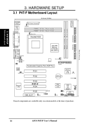
...module) RIMMA2 (16/18 bit, 184-pin module) PARALLEL PORT COM2 GAME_AUDIO Line Out Line In MODEM Mic In AUX CD1 Intel 850 Memory Controller Hub (MCH) ATX12V CPU_FAN MIC2 FLOPPY Accelerated Graphics Port (AGP Pro) Audio Codec HEADPHONE PCI1 PCI2 CR2032 3V Lithium Cell CMOS Power... Intel I/O Controller Hub (ICH2) CLRTC HDDLED Super I/O PCI3 P4T-F PCI4 PCI5 LED CNR_SLOT IR ADN 2Mbit Firmware Hub J3J3+ USB2 ASUS ASIC with Hardware Monitor PCI_FAN JEN DIP Switches OC3 CHASSIS PANEL Grayed components are available only on certain ...
...module) RIMMA2 (16/18 bit, 184-pin module) PARALLEL PORT COM2 GAME_AUDIO Line Out Line In MODEM Mic In AUX CD1 Intel 850 Memory Controller Hub (MCH) ATX12V CPU_FAN MIC2 FLOPPY Accelerated Graphics Port (AGP Pro) Audio Codec HEADPHONE PCI1 PCI2 CR2032 3V Lithium Cell CMOS Power... Intel I/O Controller Hub (ICH2) CLRTC HDDLED Super I/O PCI3 P4T-F PCI4 PCI5 LED CNR_SLOT IR ADN 2Mbit Firmware Hub J3J3+ USB2 ASUS ASIC with Hardware Monitor PCI_FAN JEN DIP Switches OC3 CHASSIS PANEL Grayed components are available only on certain ...
User Manual
Page 15
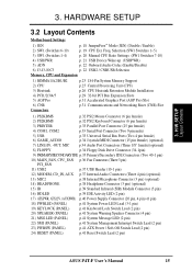
...-up (USBPWR) 5) ADN p. 22 Onboard Audio Codec (Enable/Disable) 6) J3-J3-/OC3 p. 22 USB2 / CNRUSB Selection Memory, CPU and Expansion 1) RIMMA1/A2/B1/B2 2) CPU 3) Heatsink 4) PCI1/2/3/4/5 5) AGP Pro 6) CNR Connectors p.23 184-Pin System Memory Support p.25 Central Processing Unit (CPU) p.26 CPU Heatsink Retention Module Installation p.29 32-bit PCI... System Management Interrupt Switch Lead (2 pin) 23) PWRSW (PANEL) p.41 ATX Power / Soft-Off Switch Lead (2 pin) 24) RESET (PANEL) p.41 Reset Switch Lead (2 pin) ASUS P4T-F User's Manual 15
...-up (USBPWR) 5) ADN p. 22 Onboard Audio Codec (Enable/Disable) 6) J3-J3-/OC3 p. 22 USB2 / CNRUSB Selection Memory, CPU and Expansion 1) RIMMA1/A2/B1/B2 2) CPU 3) Heatsink 4) PCI1/2/3/4/5 5) AGP Pro 6) CNR Connectors p.23 184-Pin System Memory Support p.25 Central Processing Unit (CPU) p.26 CPU Heatsink Retention Module Installation p.29 32-bit PCI... System Management Interrupt Switch Lead (2 pin) 23) PWRSW (PANEL) p.41 ATX Power / Soft-Off Switch Lead (2 pin) 24) RESET (PANEL) p.41 Reset Switch Lead (2 pin) ASUS P4T-F User's Manual 15
User Manual
Page 16
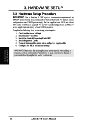
...motherboard, peripherals, and/or components. 3. HARDWARE SETUP 3.3 Hardware Setup Procedure IMPORTANT: Due to your power supply when adding or removing system components. Install memory modules 3. Install Expansion Cards 5. Failure to do so may cause severe damage to Pentium 4 CPU's power consumption requirement, an ATX12V power supply is ...For heavily-loaded configurations, an ATX12V power supply that can supply at least 8.5A on the +12V lead is required. H/W SETUP Getting Started 16 ASUS P4T-F User's Manual Connect ribbon cables, panel wires, and power supply cables 6.
...motherboard, peripherals, and/or components. 3. HARDWARE SETUP 3.3 Hardware Setup Procedure IMPORTANT: Due to your power supply when adding or removing system components. Install memory modules 3. Install Expansion Cards 5. Failure to do so may cause severe damage to Pentium 4 CPU's power consumption requirement, an ATX12V power supply is ...For heavily-loaded configurations, an ATX12V power supply that can supply at least 8.5A on the +12V lead is required. H/W SETUP Getting Started 16 ASUS P4T-F User's Manual Connect ribbon cables, panel wires, and power supply cables 6.

User Manual
Page 23
..., 128Mbit, and 256Mbit Direct RDRAM technologies. The memory configuration of a Rambus interface. 3. b. 128MB RDRAM RIMMB2 C-RIMM RIMMB1 128MB RDRAM C-RIMM RIMMA2 RIMMA1 c. 128MB RDRAM RIMMB2 128MB RDRAM RIMMB1 128MB RDRAM 128MB RDRAM RIMMA2 RIMMA1 ASUS P4T-F User's Manual 23 C-RIMMs (Continuity RIMM) ...must be identical (see below). 2. C-RIMM 128MB RDRAM C-RIMM 128MB RDRAM RIMMB2 RIMMB1 RIMMA2 RIMMA1 NOTE: When using only two memory modules, it is recommended that you...
..., 128Mbit, and 256Mbit Direct RDRAM technologies. The memory configuration of a Rambus interface. 3. b. 128MB RDRAM RIMMB2 C-RIMM RIMMB1 128MB RDRAM C-RIMM RIMMA2 RIMMA1 c. 128MB RDRAM RIMMB2 128MB RDRAM RIMMB1 128MB RDRAM 128MB RDRAM RIMMA2 RIMMA1 ASUS P4T-F User's Manual 23 C-RIMMs (Continuity RIMM) ...must be identical (see below). 2. C-RIMM 128MB RDRAM C-RIMM 128MB RDRAM RIMMB2 RIMMB1 RIMMA2 RIMMA1 NOTE: When using only two memory modules, it is recommended that you...
User Manual
Page 24
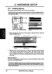
... two mounting notches on the memory module until it snaps into place. MOUNTING NOTCH RDRAM (with Heat Spreader P4T-F 184-Pin RIMM Sockets ...C-RIMM 1. ule in only one orientation. To reduce the risk of the RIMM sockets. Handle the module only by the edges. H/W SETUP System Memory EJECTOR RIBS (inside the RIMM sockets. Removing Memory To release a memory... P4T-F RIMM with heat spreader) NOTCH KEYS CONNECTORS 3. 3. HARDWARE SETUP 3.5.1 Installing Memory The memory module (RIMM) will fit in place. IMPORTANT: Do not touch the memory ...
... two mounting notches on the memory module until it snaps into place. MOUNTING NOTCH RDRAM (with Heat Spreader P4T-F 184-Pin RIMM Sockets ...C-RIMM 1. ule in only one orientation. To reduce the risk of the RIMM sockets. Handle the module only by the edges. H/W SETUP System Memory EJECTOR RIBS (inside the RIMM sockets. Removing Memory To release a memory... P4T-F RIMM with heat spreader) NOTCH KEYS CONNECTORS 3. 3. HARDWARE SETUP 3.5.1 Installing Memory The memory module (RIMM) will fit in place. IMPORTANT: Do not touch the memory ...
User Manual
Page 31
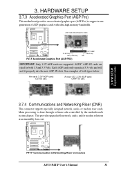
...memory bandwidth. A new 1.5 / 3.3V AGP card: OKAY to support a new generation of both 1.5 and 3.3 Volts. This provides upgradeable network, audio, and/or modem solutions at 3.3 volts and will not fit properly into the new AGP 4X slots. H/W SETUP Expansion Cards P4T-F P4T-F Communication & Networking Riser Connectors ASUS P4T...-F User's Manual 31 AGP Card without Retention Notch P4T-F 20-pin bay Rib (inside slot) P4T-F Accelerated Graphics Port (AGP PRO) TOP VIEW 28-pin...
...memory bandwidth. A new 1.5 / 3.3V AGP card: OKAY to support a new generation of both 1.5 and 3.3 Volts. This provides upgradeable network, audio, and/or modem solutions at 3.3 volts and will not fit properly into the new AGP 4X slots. H/W SETUP Expansion Cards P4T-F P4T-F Communication & Networking Riser Connectors ASUS P4T...-F User's Manual 31 AGP Card without Retention Notch P4T-F 20-pin bay Rib (inside slot) P4T-F Accelerated Graphics Port (AGP PRO) TOP VIEW 28-pin...
User Manual
Page 43
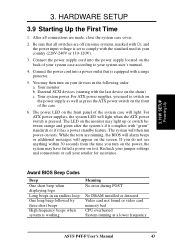
...tests are made, close the system case cover. 2. Connect the power supply cord into a power outlet that all connections are running at a lower frequency ASUS P4T-F User's Manual 43 For ATX power supplies, you turn on the front of your system case according to your devices in some systems, marked with...light when the ATX power switch is working Meaning No error during POST No DRAM installed or detected Video card not found or video card memory bad CPU overheated System running , the BIOS will alarm beeps or additional messages will appear on the front panel of the system case ...
...tests are made, close the system case cover. 2. Connect the power supply cord into a power outlet that all connections are running at a lower frequency ASUS P4T-F User's Manual 43 For ATX power supplies, you turn on the front of your system case according to your devices in some systems, marked with...light when the ATX power switch is working Meaning No error during POST No DRAM installed or detected Video card not found or video card memory bad CPU overheated System running , the BIOS will alarm beeps or additional messages will appear on the front panel of the system case ...
User Manual
Page 48
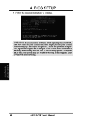
Just repeat the process, and if the problem still persists, update the original BIOS file you encounter problems while updating the new BIOS, DO NOT turn off your system since this happens, your system may not be able to continue. BIOS SETUP Updating BIOS 48 ASUS P4T-F User's Manual WARNING! If the Flash Memory Writer utility was not able to disk above. 4. Follow the onscreen instructions to boot up . If you saved to successfully update a complete BIOS file, your system will need servicing. 4. If this might prevent your system from booting up . BIOS SETUP 8.
Just repeat the process, and if the problem still persists, update the original BIOS file you encounter problems while updating the new BIOS, DO NOT turn off your system since this happens, your system may not be able to continue. BIOS SETUP Updating BIOS 48 ASUS P4T-F User's Manual WARNING! If the Flash Memory Writer utility was not able to disk above. 4. Follow the onscreen instructions to boot up . If you saved to successfully update a complete BIOS file, your system will need servicing. 4. If this might prevent your system from booting up . BIOS SETUP 8.
User Manual
Page 57
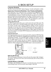
...your computer; (2)Uncap the blue jumper cap from default [1-2]; (3)Place the jumper cap onto pins [2-3] to short the RTC CMOS registry and erase its memory; (4)Uncap the jumpers and return the cap to the operational default position [1-2]; (5)Turn ON your computer; (6) Hold down during bootup and enter BIOS ...enabled, the Supervisor password is now set the passwords. You can clear the password by erasing the CMOS Real Time Clock (RTC) RAM. ASUS P4T-F User's Manual 57 The password is required for entering the BIOS Setup program and having full access to the BIOS Setup menus. To clear ...
...your computer; (2)Uncap the blue jumper cap from default [1-2]; (3)Place the jumper cap onto pins [2-3] to short the RTC CMOS registry and erase its memory; (4)Uncap the jumpers and return the cap to the operational default position [1-2]; (5)Turn ON your computer; (6) Hold down during bootup and enter BIOS ...enabled, the Supervisor password is now set the passwords. You can clear the password by erasing the CMOS Real Time Clock (RTC) RAM. ASUS P4T-F User's Manual 57 The password is required for entering the BIOS Setup program and having full access to the BIOS Setup menus. To clear ...
User Manual
Page 59
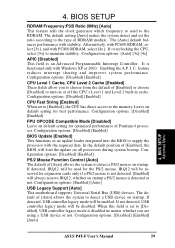
... Interrupt Controller. Configuration options: [Disabled] [Enabled] BIOS Update [Enabled] This functions as an update loader integrated into the BIOS to the memory. If detected, IRQ12 will load the update on startup. If detected, USB controller legacy mode will be used for best performance. The [Auto...:FSB Ratio (MHz) [Auto] This feature tells the clock generator which frequency to send to turn on startup. BIOS SETUP Advanced Menu ASUS P4T-F User's Manual 59 If not detected, USB controller legacy mode will be reserved for expansion cards only if a PS/2 mouse is disabled...
... Interrupt Controller. Configuration options: [Disabled] [Enabled] BIOS Update [Enabled] This functions as an update loader integrated into the BIOS to the memory. If detected, IRQ12 will load the update on startup. If detected, USB controller legacy mode will be used for best performance. The [Auto...:FSB Ratio (MHz) [Auto] This feature tells the clock generator which frequency to send to turn on startup. BIOS SETUP Advanced Menu ASUS P4T-F User's Manual 59 If not detected, USB controller legacy mode will be reserved for expansion cards only if a PS/2 mouse is disabled...
User Manual
Page 60
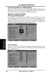
...100MHz and a fail-safe CPU internal frequency (8x100MHz). The system will then automatically take you need to set this on [Disabled]. BIOS SETUP OS/2 Onboard Memory > 64M [Disabled] When using OS/2 operating systems with a popup menu of greater than 64MB, you to the Advanced menu with installed DRAM of all... system and restart. otherwise, leave this option to improper frequency settings, power OFF your system will start up running and enter BIOS setup. 60 ASUS P4T-F User's Manual BIOS SETUP JumperFree Notes System Hangup If your system crashes or hangs due to [Enabled];
...100MHz and a fail-safe CPU internal frequency (8x100MHz). The system will then automatically take you need to set this on [Disabled]. BIOS SETUP OS/2 Onboard Memory > 64M [Disabled] When using OS/2 operating systems with a popup menu of greater than 64MB, you to the Advanced menu with installed DRAM of all... system and restart. otherwise, leave this option to improper frequency settings, power OFF your system will start up running and enter BIOS setup. 60 ASUS P4T-F User's Manual BIOS SETUP JumperFree Notes System Hangup If your system crashes or hangs due to [Enabled];
User Manual
Page 61
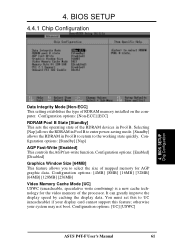
...greatly improve the display speed by caching the display data. Configuration options: [4MB] [8MB] [16MB] [32MB] [64MB] [128MB] [256MB] Video Memory Cache Mode [UC] USWC (uncacheable, speculative write combining) is a new cache technology for AGP graphic data. Configuration options: [Enabled] [Disabled] Graphics ...Window Size [64MB] This feature allows you to select the size of mapped memory for the video memory of RDRAM memory installed on the computer. BIOS SETUP Chip Configuration Data Integrity Mode [Non-ECC] This setting establishes the type ...
...greatly improve the display speed by caching the display data. Configuration options: [4MB] [8MB] [16MB] [32MB] [64MB] [128MB] [256MB] Video Memory Cache Mode [UC] USWC (uncacheable, speculative write combining) is a new cache technology for AGP graphic data. Configuration options: [Enabled] [Disabled] Graphics ...Window Size [64MB] This feature allows you to select the size of mapped memory for the video memory of RDRAM memory installed on the computer. BIOS SETUP Chip Configuration Data Integrity Mode [Non-ECC] This setting establishes the type ...

User Manual
Page 62
... options: [Disabled] [Enabled] PCI 2.1 Support [Enabled] This function allows you to reserve an address space for ISA expansion cards that memory space unavailable to a particular setting will make that require it. 4. Configuration options: [Both] [Primary] [Secondary] [Disabled] 4. Setting... the system. Expansion cards can select to 16MB. BIOS SETUP Chip Configuration 62 ASUS P4T-F User's Manual Configuration options: [Disabled] [Enabled] Onboard PCI IDE Enable [Both] You can only access memory up to enable the primary IDE channel, secondary IDE channel, both, or disable...
... options: [Disabled] [Enabled] PCI 2.1 Support [Enabled] This function allows you to reserve an address space for ISA expansion cards that memory space unavailable to a particular setting will make that require it. 4. Configuration options: [Both] [Primary] [Secondary] [Disabled] 4. Setting... the system. Expansion cards can select to 16MB. BIOS SETUP Chip Configuration 62 ASUS P4T-F User's Manual Configuration options: [Disabled] [Enabled] Onboard PCI IDE Enable [Both] You can only access memory up to enable the primary IDE channel, secondary IDE channel, both, or disable...
User Manual
Page 67
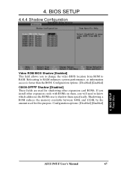
... BIOS location from ROM to RAM enhances system performance, as information access is faster than the ROM. Configuration options: [Disabled] [Enabled] 4. BIOS SETUP Power Menu ASUS P4T-F User's Manual 67 BIOS SETUP 4.4.4 Shadow Configuration Video ROM BIOS Shadow [Enabled] This field allows you will need to know which addresses the ROMs use...
... BIOS location from ROM to RAM enhances system performance, as information access is faster than the ROM. Configuration options: [Disabled] [Enabled] 4. BIOS SETUP Power Menu ASUS P4T-F User's Manual 67 BIOS SETUP 4.4.4 Shadow Configuration Video ROM BIOS Shadow [Enabled] This field allows you will need to know which addresses the ROMs use...


