Motherboard DIY Troubleshooting Guide
Page 1
® P4T-CM Intel® 850 Micro-ATX Motherboard USER'S MANUAL ASUS P4T-CM User's Manual 1
® P4T-CM Intel® 850 Micro-ATX Motherboard USER'S MANUAL ASUS P4T-CM User's Manual 1
Motherboard DIY Troubleshooting Guide
Page 2
All Rights Reserved. Product Name: ASUS P4T-CM Manual Revision: 1.00 E795 Release Date: July 2001 2 ASUS P4T-CM User's Manual Product warranty or service will not be reproduced, transmitted, transcribed, stored in a retrieval system, or translated into any ... Manual revisions are released for identification or explanation and to the owners' benefit, without the express written permission of ASUSTeK COMPUTER INC. ("ASUS"). ASUS ASSUMES NO RESPONSIBILITY OR LIABILITY FOR ANY ERRORS OR INACCURACIES THAT MAY APPEAR IN THIS MANUAL, INCLUDING THE PRODUCTS AND SOFTWARE DESCRIBED IN IT...
All Rights Reserved. Product Name: ASUS P4T-CM Manual Revision: 1.00 E795 Release Date: July 2001 2 ASUS P4T-CM User's Manual Product warranty or service will not be reproduced, transmitted, transcribed, stored in a retrieval system, or translated into any ... Manual revisions are released for identification or explanation and to the owners' benefit, without the express written permission of ASUSTeK COMPUTER INC. ("ASUS"). ASUS ASSUMES NO RESPONSIBILITY OR LIABILITY FOR ANY ERRORS OR INACCURACIES THAT MAY APPEAR IN THIS MANUAL, INCLUDING THE PRODUCTS AND SOFTWARE DESCRIBED IN IT...
Motherboard DIY Troubleshooting Guide
Page 3
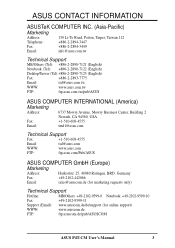
...) Notebook (Tel): +886-2-2890-7122 (English) Desktop/Server (Tel):+886-2-2890-7123 (English) Fax: +886-2-2893-7775 Email: tsd@asus.com.tw WWW: www.asus.com.tw FTP: ftp.asus.com.tw/pub/ASUS ASUS COMPUTER INTERNATIONAL (America) Marketing Address: 6737 Mowry Avenue, Mowry Business Center, Building 2 Newark, CA 94560, USA Fax: +1-510-608-4555... Fax: +49-2102-9599-11 Support (Email): www.asuscom.de/de/support (for online support) WWW: www.asuscom.de FTP: ftp.asuscom.de/pub/ASUSCOM ASUS P4T-CM User's Manual 3
...) Notebook (Tel): +886-2-2890-7122 (English) Desktop/Server (Tel):+886-2-2890-7123 (English) Fax: +886-2-2893-7775 Email: tsd@asus.com.tw WWW: www.asus.com.tw FTP: ftp.asus.com.tw/pub/ASUS ASUS COMPUTER INTERNATIONAL (America) Marketing Address: 6737 Mowry Avenue, Mowry Business Center, Building 2 Newark, CA 94560, USA Fax: +1-510-608-4555... Fax: +49-2102-9599-11 Support (Email): www.asuscom.de/de/support (for online support) WWW: www.asuscom.de FTP: ftp.asuscom.de/pub/ASUSCOM ASUS P4T-CM User's Manual 3
Motherboard DIY Troubleshooting Guide
Page 4
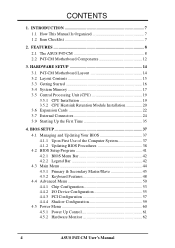
... 53 4.4.2 I/O Device Configuration 55 4.4.3 PCI Configuration 57 4.4.4 Shadow Configuration 59 4.5 Power Menu 60 4.5.1 Power Up Control 61 4.5.2 Hardware Monitor 62 4 ASUS P4T-CM User's Manual FEATURES 8 2.1 The ASUS P4T-CM 8 2.2 P4T-CM Motherboard Components 12 3. HARDWARE SETUP 14 3.1 P4T-CM Motherboard Layout 14 3.2 Layout Contents 15 3.3 Getting Started 16 3.4 System Memory 17 3.5 Central Processing Unit (CPU 19 3.5.1 CPU Installation 19...
... 53 4.4.2 I/O Device Configuration 55 4.4.3 PCI Configuration 57 4.4.4 Shadow Configuration 59 4.5 Power Menu 60 4.5.1 Power Up Control 61 4.5.2 Hardware Monitor 62 4 ASUS P4T-CM User's Manual FEATURES 8 2.1 The ASUS P4T-CM 8 2.2 P4T-CM Motherboard Components 12 3. HARDWARE SETUP 14 3.1 P4T-CM Motherboard Layout 14 3.2 Layout Contents 15 3.3 Getting Started 16 3.4 System Memory 17 3.5 Central Processing Unit (CPU 19 3.5.1 CPU Installation 19...
Motherboard DIY Troubleshooting Guide
Page 5
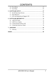
CONTENTS 4.6 Boot Menu 63 4.7 Exit Menu 65 5. SOFTWARE SETUP 67 5.1 Install Operating System 67 5.2 Start Windows 67 5.3 P4T-CM Motherboard Support CD 68 6. SOFTWARE REFERENCE 71 6.1 ASUS PC Probe 71 6.2 ASUS Live Update 76 6.4 CyberLink PowerPlayer SE 77 6.5 CyberLink VideoLive Mail 78 7. APPENDIX 81 7.1 Glossary 81 INDEX 85 ASUS P4T-CM User's Manual 5
CONTENTS 4.6 Boot Menu 63 4.7 Exit Menu 65 5. SOFTWARE SETUP 67 5.1 Install Operating System 67 5.2 Start Windows 67 5.3 P4T-CM Motherboard Support CD 68 6. SOFTWARE REFERENCE 71 6.1 ASUS PC Probe 71 6.2 ASUS Live Update 76 6.4 CyberLink PowerPlayer SE 77 6.5 CyberLink VideoLive Mail 78 7. APPENDIX 81 7.1 Glossary 81 INDEX 85 ASUS P4T-CM User's Manual 5
Motherboard DIY Troubleshooting Guide
Page 6
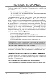
WARNING! Cet appareil numérique de la classe B est conforme à la norme NMB-003 du Canada. 6 ASUS P4T-CM User's Manual Any changes or modifications to this equipment does cause harmful interference to radio communications. This Class B digital apparatus complies with FCC Rules Part ...
WARNING! Cet appareil numérique de la classe B est conforme à la norme NMB-003 du Canada. 6 ASUS P4T-CM User's Manual Any changes or modifications to this equipment does cause harmful interference to radio communications. This Class B digital apparatus complies with FCC Rules Part ...

Motherboard DIY Troubleshooting Guide
Page 7
... drivers and utilities (1) This Motherboard User's Manual (1) CPU Retention Module (1) CD Audio Optional Items ASUS IrDA-compliant infrared module ASUS PCI-L101 Wake-On-LAN 10/ 1000 ethernet card ASUS P4T-CM User's Manual 7 1. SOFTWARE REFERENCE 7. INTRODUCTION Manual / Checklist 1. Package Contents (1) ASUS Motherboard (1) 40-pin 80-conductor ribbon cable for internal UltraDMA33/ 66/100 IDE drives...
... drivers and utilities (1) This Motherboard User's Manual (1) CPU Retention Module (1) CD Audio Optional Items ASUS IrDA-compliant infrared module ASUS PCI-L101 Wake-On-LAN 10/ 1000 ethernet card ASUS P4T-CM User's Manual 7 1. SOFTWARE REFERENCE 7. INTRODUCTION Manual / Checklist 1. Package Contents (1) ASUS Motherboard (1) 40-pin 80-conductor ribbon cable for internal UltraDMA33/ 66/100 IDE drives...
Motherboard DIY Troubleshooting Guide
Page 8
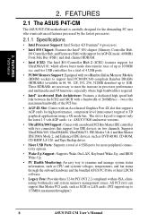
... IDE DMA Mode 2, and Enhanced IDE devices, such as SCSI or LAN cards. (PCI supports up to 133MB/s maximum throughput.) 8 ASUS P4T-CM User's Manual and two USB controllers for high performance, component level interconnect targeted at 3D graphical applications using a 4X mode bus. All PCI...allows burst mode data transfer rates of 4 USB ports for AGP 4X mode; 400MHz Front Side Bus (FSB); 2. FEATURES 2.1 The ASUS P4T-CM The ASUS P4T-CM motherboard is required. • Intel® Accelerated Hub Architecture: Features a dedicated high speed hub link between the ICH2 and MCH with...
... IDE DMA Mode 2, and Enhanced IDE devices, such as SCSI or LAN cards. (PCI supports up to 133MB/s maximum throughput.) 8 ASUS P4T-CM User's Manual and two USB controllers for high performance, component level interconnect targeted at 3D graphical applications using a 4X mode bus. All PCI...allows burst mode data transfer rates of 4 USB ports for AGP 4X mode; 400MHz Front Side Bus (FSB); 2. FEATURES 2.1 The ASUS P4T-CM The ASUS P4T-CM motherboard is required. • Intel® Accelerated Hub Architecture: Features a dedicated high speed hub link between the ICH2 and MCH with...

Motherboard DIY Troubleshooting Guide
Page 9
2. FEATURES Optional Components 2. Up to -use interface which provides more control and protection over the motherboard. ASUS P4T-CM User's Manual 9 Provides Vcore and CPU/ RDRAM frequency adjustments, boot block write protection, and HD/SCSI/MO/ ZIP/CD/Floppy boot selection. • IrDA: Supports ...
2. FEATURES Optional Components 2. Up to -use interface which provides more control and protection over the motherboard. ASUS P4T-CM User's Manual 9 Provides Vcore and CPU/ RDRAM frequency adjustments, boot block write protection, and HD/SCSI/MO/ ZIP/CD/Floppy boot selection. • IrDA: Supports ...

Motherboard DIY Troubleshooting Guide
Page 10
...66, DMA/33, and DMA and with a peak bandwidth of the motherboard meet the stringent requirements for systems and components are based on all ASUS smart series motherboards. Color-coded connectors and descriptive icons make identification easy as DVD-ROM, CD-ROM, CD-R/RW, LS-120, and Tape...Supports UltraDMA/100/66, UltraDMA/33 (IDE DMA Mode 2), PIO Modes 3 & 4, and supports Enhanced IDE devices, such as required by PC 99. 10 ASUS P4T-CM User's Manual To realize the benefits of 0.8GB/s, MCH dual channel Rambus DRAMs can be used. • Suspend and Go: Suspend-to-RAM (STR) ...
...66, DMA/33, and DMA and with a peak bandwidth of the motherboard meet the stringent requirements for systems and components are based on all ASUS smart series motherboards. Color-coded connectors and descriptive icons make identification easy as DVD-ROM, CD-ROM, CD-R/RW, LS-120, and Tape...Supports UltraDMA/100/66, UltraDMA/33 (IDE DMA Mode 2), PIO Modes 3 & 4, and supports Enhanced IDE devices, such as required by PC 99. 10 ASUS P4T-CM User's Manual To realize the benefits of 0.8GB/s, MCH dual channel Rambus DRAMs can be used. • Suspend and Go: Suspend-to-RAM (STR) ...
Motherboard DIY Troubleshooting Guide
Page 11
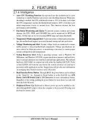
... Soft-Off mode. • Peripheral Power Up: Keyboard or Mouse power up to enable Pentium 4 processors auto throttling function. ASUS P4T-CM User's Manual 11 All the fans are more critical for future processors, so monitoring is a new technology to prevent possible application..., and CHASSIS fans can be enabled or disabled through BIOS setup to allow the computer to critical motherboard components. The onboard hardware ASUS ASIC in 3.8 Connectors for RPM and failure. FEATURES Intelligence 2. FEATURES 2.1.4 Intelligence • Auto CPU Throttling Function: Incorporated into ...
... Soft-Off mode. • Peripheral Power Up: Keyboard or Mouse power up to enable Pentium 4 processors auto throttling function. ASUS P4T-CM User's Manual 11 All the fans are more critical for future processors, so monitoring is a new technology to prevent possible application..., and CHASSIS fans can be enabled or disabled through BIOS setup to allow the computer to critical motherboard components. The onboard hardware ASUS ASIC in 3.8 Connectors for RPM and failure. FEATURES Intelligence 2. FEATURES 2.1.4 Intelligence • Auto CPU Throttling Function: Incorporated into ...
Motherboard DIY Troubleshooting Guide
Page 12
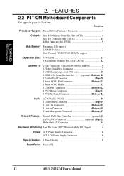
Location Processor Support Socket 423 for locations. 2. FEATURES 2.2 P4T-CM Motherboard Components See opposite page for Pentium 4 Processors 1 Chipsets Intel 850 Memory Controller Hub (MCH 2 Intel I/O Controller Hub 2 (ICH2 11 4Mbit Firmware Hub (FWH 9 Main ... Low Pin Count (LPC) Winbond Multi-I/O Chipset 4 Power ATX Power Supply Connector 6 ATX 12V Power Supply Connector 6 Special Feature 1 iPanel Header 8 Form Factor MicroATX 12 ASUS P4T-CM User's Manual FEATURES MB Components 2.
Location Processor Support Socket 423 for locations. 2. FEATURES 2.2 P4T-CM Motherboard Components See opposite page for Pentium 4 Processors 1 Chipsets Intel 850 Memory Controller Hub (MCH 2 Intel I/O Controller Hub 2 (ICH2 11 4Mbit Firmware Hub (FWH 9 Main ... Low Pin Count (LPC) Winbond Multi-I/O Chipset 4 Power ATX Power Supply Connector 6 ATX 12V Power Supply Connector 6 Special Feature 1 iPanel Header 8 Form Factor MicroATX 12 ASUS P4T-CM User's Manual FEATURES MB Components 2.
Motherboard DIY Troubleshooting Guide
Page 14
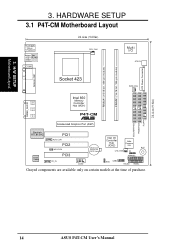
SECONDARY IDE PRIMARY IDE FLOPPY 24.4cm (9.6in) 14 ASUS P4T-CM User's Manual 3. HARDWARE SETUP 3.1 P4T-CM Motherboard Layout PS/2KBMS T: Mouse B: Keyboard Bottom: Top: USB1 RJ-45 USB2 COM1 24.4cm (9.60in) CPU_FAN Multi I/O ATX12V ATX Power Connector RIMMA1 (... module) RIMMB1 (16/18 bit, 184-pin module) PARALLEL PORT Socket 423 PWR_FAN GAME_AUDIO Intel 850 Memory Line Out Controller Hub (MCH) Line In Mic P4T-CM In ® Accelerated Graphics Port (AGP) 1 1 1 Realtek RTL8139C Audio Codec PCI1 AUX_CON PCI2 WOLCON PCI3 CD_IN CR2032 3V Lithium Cell CMOS Power COM2 ...
SECONDARY IDE PRIMARY IDE FLOPPY 24.4cm (9.6in) 14 ASUS P4T-CM User's Manual 3. HARDWARE SETUP 3.1 P4T-CM Motherboard Layout PS/2KBMS T: Mouse B: Keyboard Bottom: Top: USB1 RJ-45 USB2 COM1 24.4cm (9.60in) CPU_FAN Multi I/O ATX12V ATX Power Connector RIMMA1 (... module) RIMMB1 (16/18 bit, 184-pin module) PARALLEL PORT Socket 423 PWR_FAN GAME_AUDIO Intel 850 Memory Line Out Controller Hub (MCH) Line In Mic P4T-CM In ® Accelerated Graphics Port (AGP) 1 1 1 Realtek RTL8139C Audio Codec PCI1 AUX_CON PCI2 WOLCON PCI3 CD_IN CR2032 3V Lithium Cell CMOS Power COM2 ...
Motherboard DIY Troubleshooting Guide
Page 15
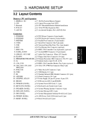
... System Management Interrupt Switch Lead (2 pin) 26) PWRSW (PANEL) p.34 ATX Power / Soft-Off Switch Lead (2 pin) 27) RESET (PANEL) p.34 Reset Switch Lead (2 pin) ASUS P4T-CM User's Manual 15
... System Management Interrupt Switch Lead (2 pin) 26) PWRSW (PANEL) p.34 ATX Power / Soft-Off Switch Lead (2 pin) 27) RESET (PANEL) p.34 Reset Switch Lead (2 pin) ASUS P4T-CM User's Manual 15

Motherboard DIY Troubleshooting Guide
Page 16
...-loaded configurations, an ATX12V power supply that can supply at least 8.5A on the bag that you unplug your motherboard, peripherals, and/or components. 16 ASUS P4T-CM User's Manual Use a grounded wrist strap before you do so may cause severe damage to a metal object, such as the power supply case. 3. For typical...
...-loaded configurations, an ATX12V power supply that can supply at least 8.5A on the bag that you unplug your motherboard, peripherals, and/or components. 16 ASUS P4T-CM User's Manual Use a grounded wrist strap before you do so may cause severe damage to a metal object, such as the power supply case. 3. For typical...
Motherboard DIY Troubleshooting Guide
Page 17
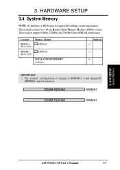
.... 128MB RDRAM RIMMB1 128MB RDRAM RIMMA1 3. Location Memory Module RIMMA1 (Rows 0&1) RDRAM RIMMB1 (Rows 2&3) RDRAM TOTAL SYSTEM MEMORY (1GB Max) Subtotal x 1 x 1 = IMPORTANT 1. H/W SETUP System Memory ASUS P4T-CM User's Manual 17 3. These sockets support 64Mbit, 128Mbit, and 256Mbit Direct RDRAM technologies. HARDWARE SETUP 3.4 System Memory NOTE: No hardware or BIOS setup is required...
.... 128MB RDRAM RIMMB1 128MB RDRAM RIMMA1 3. Location Memory Module RIMMA1 (Rows 0&1) RDRAM RIMMB1 (Rows 2&3) RDRAM TOTAL SYSTEM MEMORY (1GB Max) Subtotal x 1 x 1 = IMPORTANT 1. H/W SETUP System Memory ASUS P4T-CM User's Manual 17 3. These sockets support 64Mbit, 128Mbit, and 256Mbit Direct RDRAM technologies. HARDWARE SETUP 3.4 System Memory NOTE: No hardware or BIOS setup is required...
Motherboard DIY Troubleshooting Guide
Page 18
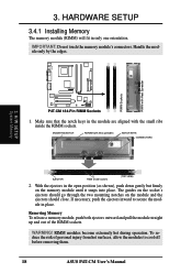
...-Pin RIMM Sockets 1. IMPORTANT: Do not touch the memory module's connectors. If necessary, push the ejectors inward to cool off before removing them. 18 ASUS P4T-CM User's Manual RIMM Sockets RIMM with heat spreader) NOTCH KEYS CONNECTORS 3. H/W SETUP System Memory EJECTOR RIBS (inside the RIMM sockets. WARNING! The guides on the ...
...-Pin RIMM Sockets 1. IMPORTANT: Do not touch the memory module's connectors. If necessary, push the ejectors inward to cool off before removing them. 18 ASUS P4T-CM User's Manual RIMM Sockets RIMM with heat spreader) NOTCH KEYS CONNECTORS 3. H/W SETUP System Memory EJECTOR RIBS (inside the RIMM sockets. WARNING! The guides on the ...
Motherboard DIY Troubleshooting Guide
Page 19
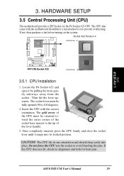
...Once completely inserted, press the CPU firmly and close the socket lever until it by pulling the lever gently sideways away from the socket. ASUS P4T-CM User's Manual 19 If the CPU does not fit, check its locked position. HARDWARE SETUP 3.5 Central Processing Unit (CPU) The motherboard ...that came with the correct orientation. If not, then purchase a fan before turning on the system. Socket 423 Pentium 4 Gold Arrow P4T-CM ® P4T-CM Socket 423 Gold Arrow 3.5.1 CPU Installation 1. Locate the P4 Socket 423 and open it snaps into the socket to prevent overheating. The ...
...Once completely inserted, press the CPU firmly and close the socket lever until it by pulling the lever gently sideways away from the socket. ASUS P4T-CM User's Manual 19 If the CPU does not fit, check its locked position. HARDWARE SETUP 3.5 Central Processing Unit (CPU) The motherboard ...that came with the correct orientation. If not, then purchase a fan before turning on the system. Socket 423 Pentium 4 Gold Arrow P4T-CM ® P4T-CM Socket 423 Gold Arrow 3.5.1 CPU Installation 1. Locate the P4 Socket 423 and open it snaps into the socket to prevent overheating. The ...
Motherboard DIY Troubleshooting Guide
Page 20
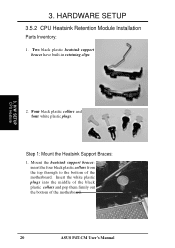
Step 1: Mount the Heatsink Support Braces: 1. Mount the heatsink support braces: insert the four black plastic collars from the top through to the bottom of the motherboard. 20 ASUS P4T-CM User's Manual 3. Insert the white plastic plugs into the middle of the black plastic collars and pop them firmly out the bottom of the motherboard. HARDWARE SETUP 3.5.2 CPU Heatsink Retention Module Installation Parts Inventory: 1. Two black plastic heatsink support braces have built-in retaining clips. 3. Four black plastic collars and four white plastic plugs. H/W SETUP CPU Heatsink 2.
Step 1: Mount the Heatsink Support Braces: 1. Mount the heatsink support braces: insert the four black plastic collars from the top through to the bottom of the motherboard. 20 ASUS P4T-CM User's Manual 3. Insert the white plastic plugs into the middle of the black plastic collars and pop them firmly out the bottom of the motherboard. HARDWARE SETUP 3.5.2 CPU Heatsink Retention Module Installation Parts Inventory: 1. Two black plastic heatsink support braces have built-in retaining clips. 3. Four black plastic collars and four white plastic plugs. H/W SETUP CPU Heatsink 2.
Motherboard DIY Troubleshooting Guide
Page 21
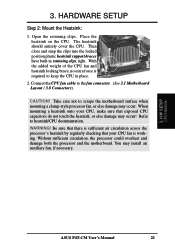
... Step 2: Mount the Heatsink: 1. Then close and snap the clips into the locked position plastic heatsink support braces have built-in place. 2. H/W SETUP CPU Heatsink ASUS P4T-CM User's Manual 21 Connect the CPU fan cable to heatsink/CPU documentation. Be sure that there is sufficient air circulation across the processor's heatsink by...
... Step 2: Mount the Heatsink: 1. Then close and snap the clips into the locked position plastic heatsink support braces have built-in place. 2. H/W SETUP CPU Heatsink ASUS P4T-CM User's Manual 21 Connect the CPU fan cable to heatsink/CPU documentation. Be sure that there is sufficient air circulation across the processor's heatsink by...


