Motherboard DIY Troubleshooting Guide
Page 10
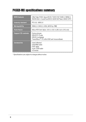
DMI 2.0, WOL/WOR by PME Micro-ATX form factor: 9.6 in x 9.6 in (24.5 cm x 24.5 cm) Device drivers ASUS PC Probe ASUS LiveUpdate Trend Micro™ PC-cillin 2002 anti-virus software User's Manual UltraDMA cable FDD cable 9-pin COM cable I/O shield * Specifications are subject to change without notice. x P4SGX-MX specifications summary BIOS features Industry standard Manageability Form Factor Support CD contents Accessories 2Mb Flash ROM, Award BIOS, TCAV, PnP, DMI2.0, WfM2.0, SM BIOS2.3, CrashFree BIOS, ASUS EZ Flash, ASUS CP.R PCI 2.2, USB 2.0 WfM 2.0.
DMI 2.0, WOL/WOR by PME Micro-ATX form factor: 9.6 in x 9.6 in (24.5 cm x 24.5 cm) Device drivers ASUS PC Probe ASUS LiveUpdate Trend Micro™ PC-cillin 2002 anti-virus software User's Manual UltraDMA cable FDD cable 9-pin COM cable I/O shield * Specifications are subject to change without notice. x P4SGX-MX specifications summary BIOS features Industry standard Manageability Form Factor Support CD contents Accessories 2Mb Flash ROM, Award BIOS, TCAV, PnP, DMI2.0, WfM2.0, SM BIOS2.3, CrashFree BIOS, ASUS EZ Flash, ASUS CP.R PCI 2.2, USB 2.0 WfM 2.0.
Motherboard DIY Troubleshooting Guide
Page 12
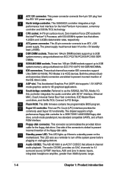
.../66/100 IDE cable Ribbon cable for a 3.5-inch floppy drive I/O shield Bag of extra jumper caps User Guide 9-pin COM cable If any of ASUS quality motherboards! Thank you start installing the motherboard, and hardware devices on it another standout in 478-pin package coupled with the PC2700/2100/1600 DDR DIMMs or the PC133/PC100 SDRAM DIMMs, high-resolution graphics via an AGP 4X slot, USB 2.0, and 6-channel audio features, the P4SGX-MX is...
.../66/100 IDE cable Ribbon cable for a 3.5-inch floppy drive I/O shield Bag of extra jumper caps User Guide 9-pin COM cable If any of ASUS quality motherboards! Thank you start installing the motherboard, and hardware devices on it another standout in 478-pin package coupled with the PC2700/2100/1600 DDR DIMMs or the PC133/PC100 SDRAM DIMMs, high-resolution graphics via an AGP 4X slot, USB 2.0, and 6-channel audio features, the P4SGX-MX is...
Motherboard DIY Troubleshooting Guide
Page 14
...-pin DIMM sockets support up to PCI Bridge. 10 Flash ROM. This Accelerated Graphics Port (AGP) slot supports 1.5V AGP4X mode graphics cards for a 360K/720K/1.44M/2.88M floppy disk drive, a multi-mode parallel port, two standard compatible UARTs, and a Flash ROM interface. 12 Floppy disk connector. Referred to as a reminder to prevent incorrect insertion of the IDE ribbon cable. 8 AGP slot. This Low Pin Count (LPC) interface provides the commonly used Super I /O controller. This power connector connects the 4-pin 12V plug from the ATX 12V power supply...
...-pin DIMM sockets support up to PCI Bridge. 10 Flash ROM. This Accelerated Graphics Port (AGP) slot supports 1.5V AGP4X mode graphics cards for a 360K/720K/1.44M/2.88M floppy disk drive, a multi-mode parallel port, two standard compatible UARTs, and a Flash ROM interface. 12 Floppy disk connector. Referred to as a reminder to prevent incorrect insertion of the IDE ribbon cable. 8 AGP slot. This Low Pin Count (LPC) interface provides the commonly used Super I /O controller. This power connector connects the 4-pin 12V plug from the ATX 12V power supply...
Motherboard DIY Troubleshooting Guide
Page 15
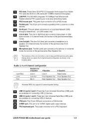
... Front Speaker Out Rear Speaker Out Windows 98SE only supports 4 channel speaker setting. 23 USB 2.0 ports 3 and 4. This port is for connecting USB 2.0 devices. 25 VGA port. This port allows connection to a VGA monitor. 26 S/PDIF port. This Line In (light blue) jack connects a tape player or other devices. 19 RJ-45 port. 15 PCI slots. These two 4-pin Universal Serial Bus (USB) ports are available for S/PDIF digital audio output devices. 27 PS/2 keyboard port. This 15-pin VGA port connects to a Local Area Network (LAN) through a network hub. (on LAN models only...
... Front Speaker Out Rear Speaker Out Windows 98SE only supports 4 channel speaker setting. 23 USB 2.0 ports 3 and 4. This port is for connecting USB 2.0 devices. 25 VGA port. This port allows connection to a VGA monitor. 26 S/PDIF port. This Line In (light blue) jack connects a tape player or other devices. 19 RJ-45 port. 15 PCI slots. These two 4-pin Universal Serial Bus (USB) ports are available for S/PDIF digital audio output devices. 27 PS/2 keyboard port. This 15-pin VGA port connects to a Local Area Network (LAN) through a network hub. (on LAN models only...
Motherboard DIY Troubleshooting Guide
Page 23
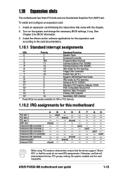
... PCI devices. 1.10.2 IRQ assignments for BIOS information. 3. Onboard VGA shared - - - - used Onboard USB controller 2 - - - - - PCI slot 3 - - - shared - Onboard audio - - AGP slot shared - - - - ASUS P4SGX-MX motherboard user guide 1-13 GH used - - Turn on shared slots, ensure that the drivers support "Share IRQ" or that came with the chassis. 2. 1.10 Expansion slots The motherboard has three PCI slots and one Accelerated Graphics Port (AGP) slot. To install and configure an expansion card: 1. shared - - Onboard USB controller 3 - - - - - Onboard USB...
... PCI devices. 1.10.2 IRQ assignments for BIOS information. 3. Onboard VGA shared - - - - used Onboard USB controller 2 - - - - - PCI slot 3 - - - shared - Onboard audio - - AGP slot shared - - - - ASUS P4SGX-MX motherboard user guide 1-13 GH used - - Turn on shared slots, ensure that the drivers support "Share IRQ" or that came with the chassis. 2. 1.10 Expansion slots The motherboard has three PCI slots and one Accelerated Graphics Port (AGP) slot. To install and configure an expansion card: 1. shared - - Onboard USB controller 3 - - - - - Onboard USB...
Motherboard DIY Troubleshooting Guide
Page 25
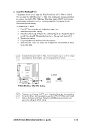
... system passwords, is powered by erasing the CMOS RTC RAM data. You can automatically reset parameter settings to default values. Clear RTC RAM (CLRTC1) This jumper allows you to re-enter data. Replace the battery. 5. Plug the power cord and turn ON the computer. 6. Except when clearing the RTC RAM, never remove the cap on pins 2-3 for about 5~10 seconds, then move the cap back to overclocking, use the C.P.R. (CPU Parameter Recall) feature. ASUS P4SGX-MX motherboard user guide...
... system passwords, is powered by erasing the CMOS RTC RAM data. You can automatically reset parameter settings to default values. Clear RTC RAM (CLRTC1) This jumper allows you to re-enter data. Replace the battery. 5. Plug the power cord and turn ON the computer. 6. Except when clearing the RTC RAM, never remove the cap on pins 2-3 for about 5~10 seconds, then move the cap back to overclocking, use the C.P.R. (CPU Parameter Recall) feature. ASUS P4SGX-MX motherboard user guide...

Motherboard DIY Troubleshooting Guide
Page 26
...configure two hard disks to be both master devices with pin 5 plug). Pin 20 on each IDE connector is removed to prevent incorrect insertion when using ribbon cables with two ribbon cables - Floppy disk drive connector (34-1 pin FLOPPY1) This connector supports the provided floppy drive ribbon cable. P4SGX-MX Floppy Disk Drive Connector 2. 1.12 Connectors This section describes and illustrates the internal connectors on the floppy ribbon cable to PIN 1. If you must configure the second drive as a slave device by setting its jumper accordingly. If you install two hard disks...
...configure two hard disks to be both master devices with pin 5 plug). Pin 20 on each IDE connector is removed to prevent incorrect insertion when using ribbon cables with two ribbon cables - Floppy disk drive connector (34-1 pin FLOPPY1) This connector supports the provided floppy drive ribbon cable. P4SGX-MX Floppy Disk Drive Connector 2. 1.12 Connectors This section describes and illustrates the internal connectors on the floppy ribbon cable to PIN 1. If you must configure the second drive as a slave device by setting its jumper accordingly. If you install two hard disks...

Motherboard DIY Troubleshooting Guide
Page 31
...the system power. • Hard Disk Activity Lead (2-pin IDE_LED) This connector supplies power to the system power LED. System panel connector (20-pin PANEL1) This connector accommodates several system front panel functions. The LED lights up . Attach the casemounted suspend switch to this LED to the primary or secondary IDE connector cause this 2-pin connector. • ATX Power Switch / Soft-Off Switch Lead (2-pin PWRBTN) This connector connects a switch that controls the system power. ASUS P4SGX-MX motherboard user guide 1-21 Pressing the power switch while in sleep mode...
...the system power. • Hard Disk Activity Lead (2-pin IDE_LED) This connector supplies power to the system power LED. System panel connector (20-pin PANEL1) This connector accommodates several system front panel functions. The LED lights up . Attach the casemounted suspend switch to this LED to the primary or secondary IDE connector cause this 2-pin connector. • ATX Power Switch / Soft-Off Switch Lead (2-pin PWRBTN) This connector connects a switch that controls the system power. ASUS P4SGX-MX motherboard user guide 1-21 Pressing the power switch while in sleep mode...

Motherboard DIY Troubleshooting Guide
Page 34
... COMPUTER INC. [Onboard BIOS Information] BIOS Version : ASUS P4SGX-MX ACPI BIOS Revision 1002 BIOS Model : P4SGX-MX BIOS Built Date : 12/09/02 Please Enter File Name for reference only. Download the latest BIOS file from the ASUS website (see on page viii). Write down the BIOS file name on a piece of booting from A:\, Press [ESC] to step 5 without having to go through the long process of paper. 2.1 Managing and updating your screen may not...
... COMPUTER INC. [Onboard BIOS Information] BIOS Version : ASUS P4SGX-MX ACPI BIOS Revision 1002 BIOS Model : P4SGX-MX BIOS Built Date : 12/09/02 Please Enter File Name for reference only. Download the latest BIOS file from the ASUS website (see on page viii). Write down the BIOS file name on a piece of booting from A:\, Press [ESC] to step 5 without having to go through the long process of paper. 2.1 Managing and updating your screen may not...

Motherboard DIY Troubleshooting Guide
Page 40
... screen has a menu bar with the opportunity to the advanced features. 2.2 BIOS Setup program This motherboard supports a programmable Flash ROM that the computer can recognize these changes and record them in the CMOS RAM of the Flash ROM. Even if you with the following selections: MAIN ADVANCED POWER BOOT EXIT Use this program. When you start up the computer, the system provides you are installing a motherboard, reconfiguring your system using the BIOS Setup...
... screen has a menu bar with the opportunity to the advanced features. 2.2 BIOS Setup program This motherboard supports a programmable Flash ROM that the computer can recognize these changes and record them in the CMOS RAM of the Flash ROM. Even if you with the following selections: MAIN ADVANCED POWER BOOT EXIT Use this program. When you start up the computer, the system provides you are installing a motherboard, reconfiguring your system using the BIOS Setup...

Motherboard DIY Troubleshooting Guide
Page 43
... password is powered by the onboard button cell battery. The BIOS Setup program allows you to [Disabled]. The RAM data containing the password information is set to set to the BIOS during the boot process. ASUS P4SGX-MX motherboard user guide 2-11 Configuration options: [Disabled] [Enabled] Supervisor Password [Disabled] / User Password [Disabled] These fields allow you to support older Japanese floppy drives. The password is required to specify two different passwords: a Supervisor password and a User password. The passwords control access to [Enabled]. Configuration...
... password is powered by the onboard button cell battery. The BIOS Setup program allows you to [Disabled]. The RAM data containing the password information is set to set to the BIOS during the boot process. ASUS P4SGX-MX motherboard user guide 2-11 Configuration options: [Disabled] [Enabled] Supervisor Password [Disabled] / User Password [Disabled] These fields allow you to support older Japanese floppy drives. The password is required to specify two different passwords: a Supervisor password and a User password. The passwords control access to [Enabled]. Configuration...

Motherboard DIY Troubleshooting Guide
Page 45
.... To make changes to this field. Make sure to set the Type field to [User Type HDD] and the Translation Method field to [Manual]. for the hard disk drive that you entered. When the Main menu appears, the hard disk drive field displays the size for IDE magneto optical disk drives [Other ATAPI Device] - This is necessary for the Type field are removing a drive and not replacing it, select [None]. After entering the IDE hard disk drive information into BIOS, use a disk utility, such as...
.... To make changes to this field. Make sure to set the Type field to [User Type HDD] and the Translation Method field to [Manual]. for the hard disk drive that you entered. When the Main menu appears, the hard disk drive field displays the size for IDE magneto optical disk drives [Other ATAPI Device] - This is necessary for the Type field are removing a drive and not replacing it, select [None]. After entering the IDE hard disk drive information into BIOS, use a disk utility, such as...

Motherboard DIY Troubleshooting Guide
Page 46
... by the BIOS based on the drive information you to enable or disable the S.M.A.R.T. (Self-Monitoring, Analysis and Reporting Technology) system that utilizes internal hard disk drive monitoring technology. Configuration options: [Disabled] [Enabled] PIO Mode [4] This option lets you set it manually. Configuration options: [0] [1] [2] [3] [4] Ultra DMA Mode [Disabled] Ultra DMA capability allows improved transfer speeds and data integrity for the drive. To make changes to this field, set the Type field to [User Type HDD]. To make changes to this field, set the Type field to...
... by the BIOS based on the drive information you to enable or disable the S.M.A.R.T. (Self-Monitoring, Analysis and Reporting Technology) system that utilizes internal hard disk drive monitoring technology. Configuration options: [Disabled] [Enabled] PIO Mode [4] This option lets you set it manually. Configuration options: [0] [1] [2] [3] [4] Ultra DMA Mode [Disabled] Ultra DMA capability allows improved transfer speeds and data integrity for the drive. To make changes to this field, set the Type field to [User Type HDD]. To make changes to this field, set the Type field to...

Motherboard DIY Troubleshooting Guide
Page 48
... you set to [Disabled], the USB controller legacy mode is detected at startup. If not detected, the USB controller legacy mode is set this field to [Enabled], the BIOS loads the update on or off the CPU Level 2 built-in the popup menu vary according to the default setting [Disabled]. Configuration options: [Disabled] [Enabled] [Auto] OS/2 Onboard Memory > 64M [Disabled] When using a USB device. Configuration options: [Enabled] [Auto] USB Legacy Support [Auto] This motherboard supports Universal Serial Bus (USB) devices. When you to choose from the default [Enabled] or...
... you set to [Disabled], the USB controller legacy mode is detected at startup. If not detected, the USB controller legacy mode is set this field to [Enabled], the BIOS loads the update on or off the CPU Level 2 built-in the popup menu vary according to the default setting [Disabled]. Configuration options: [Disabled] [Enabled] [Auto] OS/2 Onboard Memory > 64M [Disabled] When using a USB device. Configuration options: [Enabled] [Auto] USB Legacy Support [Auto] This motherboard supports Universal Serial Bus (USB) devices. When you to choose from the default [Enabled] or...
Motherboard DIY Troubleshooting Guide
Page 50
... motherboard feature to [1X Mode], the AGP interface only provides a peak data throughput of 266MB/s even if you are using an AGP 4X card. Configuration options: [Disabled] [Enabled] Onboard PCI IDE [Both] This field allows you to enable either the primary IDE channel or secondary IDE channel, or both channels to [Disabled]. Configuration options: [Both] [Primary] [Secondary] [Disabled] IDE Bus Master Support [Enabled] This item controls the IDE Bus Master support for AGP graphic data. Configuration options: [4M] [8M] [16M] [32M] [64M] Video Memory...
... motherboard feature to [1X Mode], the AGP interface only provides a peak data throughput of 266MB/s even if you are using an AGP 4X card. Configuration options: [Disabled] [Enabled] Onboard PCI IDE [Both] This field allows you to enable either the primary IDE channel or secondary IDE channel, or both channels to [Disabled]. Configuration options: [Both] [Primary] [Secondary] [Disabled] IDE Bus Master Support [Enabled] This item controls the IDE Bus Master support for AGP graphic data. Configuration options: [4M] [8M] [16M] [32M] [64M] Video Memory...
Motherboard DIY Troubleshooting Guide
Page 52
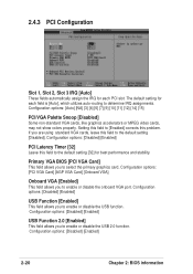
... graphics card. The default setting for each PCI slot. Primary VGA BIOS [PCI VGA Card] This field allows you to enable or disable the USB function. Configuration options: [Disabled] [Enabled] USB Function 2.0 [Enabled] This field allows you are using standard VGA cards, leave this problem. 2.4.3 PCI Configuration Slot 1, Slot 2, Slot 3 IRQ [Auto] These fields automatically assign the IRQ for each field is [Auto], which utilizes auto-routing to determine IRQ assignments. If you to enable or disable the onboard VGA port. Configuration options: [PCI VGA Card] [AGP VGA Card] [Onboard VGA...
... graphics card. The default setting for each PCI slot. Primary VGA BIOS [PCI VGA Card] This field allows you to enable or disable the USB function. Configuration options: [Disabled] [Enabled] USB Function 2.0 [Enabled] This field allows you are using standard VGA cards, leave this problem. 2.4.3 PCI Configuration Slot 1, Slot 2, Slot 3 IRQ [Auto] These fields automatically assign the IRQ for each field is [Auto], which utilizes auto-routing to determine IRQ assignments. If you to enable or disable the onboard VGA port. Configuration options: [PCI VGA Card] [AGP VGA Card] [Onboard VGA...
Motherboard DIY Troubleshooting Guide
Page 53
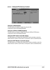
...options: [Disabled] [Auto] ASUS P4SGX-MX motherboard user guide 2-21 Configuration options: [Disabled] [Auto] Onboard AC97 Modem Controller [Auto] This field allows you to disable the onboard AC97 audio controller or set to the default [Auto] for optimum performance. Configuration options: [Disabled] [Enabled] Onboard AC97 Audio Controller [Auto] This field allows you to disable the onboard AC97 modem controller or set to the default [Auto] for optimum performance. Configuration options: [Disabled] [Enabled] Onboard LAN Boot ROM [Disabled] This field allows you enable or disable...
...options: [Disabled] [Auto] ASUS P4SGX-MX motherboard user guide 2-21 Configuration options: [Disabled] [Auto] Onboard AC97 Modem Controller [Auto] This field allows you to disable the onboard AC97 audio controller or set to the default [Auto] for optimum performance. Configuration options: [Disabled] [Enabled] Onboard AC97 Audio Controller [Auto] This field allows you to disable the onboard AC97 modem controller or set to the default [Auto] for optimum performance. Configuration options: [Disabled] [Enabled] Onboard LAN Boot ROM [Disabled] This field allows you enable or disable...

Motherboard DIY Troubleshooting Guide
Page 59
... you to determine whether the drive has 40 or 80 tracks. It also holds the complete record of how the system was booted. Configuration options: [PIC] [APIC] ASUS P4SGX-MX motherboard user guide 2-27 Reset Configuration Data [No] The Extended System Configuration Data (ESCD) contain information about nonPnP devices. Configuration options: [Disabled] [Enabled] Quick Power On Self Test [Enabled] This field speeds up the Power-On-Self Test (POST) routine by skipping retesting...
... you to determine whether the drive has 40 or 80 tracks. It also holds the complete record of how the system was booted. Configuration options: [PIC] [APIC] ASUS P4SGX-MX motherboard user guide 2-27 Reset Configuration Data [No] The Extended System Configuration Data (ESCD) contain information about nonPnP devices. Configuration options: [Disabled] [Enabled] Quick Power On Self Test [Enabled] This field speeds up the Power-On-Self Test (POST) routine by skipping retesting...

Motherboard DIY Troubleshooting Guide
Page 62
... The support CD that came with the motherboard contains useful software and several utility drivers that enhance the motherboard features. Visit the ASUS website for general reference only. The contents of your CD-ROM drive. Because motherboard settings and hardware options vary, use the setup procedures presented in the support CD to display the menu. 3-2 Chapter 3: Software support Refer to change at any time without notice. 3.1 Install an operating system This motherboard supports Windows 98SE...
... The support CD that came with the motherboard contains useful software and several utility drivers that enhance the motherboard features. Visit the ASUS website for general reference only. The contents of your CD-ROM drive. Because motherboard settings and hardware options vary, use the setup procedures presented in the support CD to display the menu. 3-2 Chapter 3: Software support Refer to change at any time without notice. 3.1 Install an operating system This motherboard supports Windows 98SE...

Motherboard DIY Troubleshooting Guide
Page 63
... first screen to install it. SiS AGP Driver Click this item to display the SoundMAX Control Panel. SiS PCI LAN Driver Click this motherboard. Simply click on the SoundMAX Digital Integrated Audio icon to install the 650/651 driver for your AGP card. ASUS PC Probe This smart utility monitors the fan speed, CPU temperature, and system voltages, and alerts you on the lower right corner of the second screen. 5.2.3 Software and drivers description The menu lists the drivers...
... first screen to install it. SiS AGP Driver Click this item to display the SoundMAX Control Panel. SiS PCI LAN Driver Click this motherboard. Simply click on the SoundMAX Digital Integrated Audio icon to install the 650/651 driver for your AGP card. ASUS PC Probe This smart utility monitors the fan speed, CPU temperature, and system voltages, and alerts you on the lower right corner of the second screen. 5.2.3 Software and drivers description The menu lists the drivers...


