User Guide
Page 5
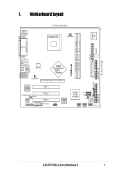
Motherboard layout PS/2 T: Mouse B: Keyboard COM1 24.5cm (9.64in) Socket 478 CPU_FAN1 Super I/O FLOPPY1 BUZZER P4SD-LA DDR DIMM1 (64/72 bit, 184-pin module) DDR DIMM2 (64/72 bit, 184-pin module) PARALLEL PORT VGA Bottom: USB1 USB2 Top: 1394 Bottom: .../F PCI 2 Audio Codec PCI 3 CD_IN AUX SPEAKER OUT FRONT HP-OUT 1394 TI43AB22A 1394 PHY 01 23 BATTERY1 Intel ICH5 Chipset P31 P30 J19 4Mb BIOS USB2 USB1 HPANEL ATX Power Connector 24.5cm (9.64in) SECONDARY IDE PRIMARY IDE ASUS P4SD-LA motherboard 1 1.
Motherboard layout PS/2 T: Mouse B: Keyboard COM1 24.5cm (9.64in) Socket 478 CPU_FAN1 Super I/O FLOPPY1 BUZZER P4SD-LA DDR DIMM1 (64/72 bit, 184-pin module) DDR DIMM2 (64/72 bit, 184-pin module) PARALLEL PORT VGA Bottom: USB1 USB2 Top: 1394 Bottom: .../F PCI 2 Audio Codec PCI 3 CD_IN AUX SPEAKER OUT FRONT HP-OUT 1394 TI43AB22A 1394 PHY 01 23 BATTERY1 Intel ICH5 Chipset P31 P30 J19 4Mb BIOS USB2 USB1 HPANEL ATX Power Connector 24.5cm (9.64in) SECONDARY IDE PRIMARY IDE ASUS P4SD-LA motherboard 1 1.
User Guide
Page 9
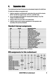
... came with the chassis. See Chapter 2 for this motherboard A B C D E F GH PCI slot 1 - - - - - Install the drivers and/or software applications for ISA or PCI devices. IRQ assignments for BIOS information. 3. PCI slot 3 shared AGP slot shared ... the system and change the necessary BIOS settings, if any. Assign an IRQ to the card documentation. PCI slot 2 - - - - - - used - - - - - - shared - - - - 4. NOTE: The AGP slot supports only +0.8V and +1.5V AGP cards. 2. ASUS P4SD-LA motherboard 5 Expansion slots The motherboard has three PCI slots and one ...
... came with the chassis. See Chapter 2 for this motherboard A B C D E F GH PCI slot 1 - - - - - Install the drivers and/or software applications for ISA or PCI devices. IRQ assignments for BIOS information. 3. PCI slot 3 shared AGP slot shared ... the system and change the necessary BIOS settings, if any. Assign an IRQ to the card documentation. PCI slot 2 - - - - - - used - - - - - - shared - - - - 4. NOTE: The AGP slot supports only +0.8V and +1.5V AGP cards. 2. ASUS P4SD-LA motherboard 5 Expansion slots The motherboard has three PCI slots and one ...
User Guide
Page 11
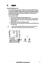
...-enter data. Keep the cap on jumper J19 default position. To erase the RTC RAM: 1. Hold down the key during the boot process and enter BIOS setup to clear the Real Time Clock (RTC) RAM in CMOS, that include system setup information such as system passwords, is powered by erasing the... RAM data. Turn OFF the computer and unplug the power cord. 2. 5. The RAM data in CMOS. Move the jumper cap from pins 2-3 (Normal) to pins 2-3. 3. P4SD-LA P4SD-LA Clear RTC RAM J19 3 2 1 Clear CMOS 3 2 1 Normal (Default) ASUS P4SD-LA motherboard 7
...-enter data. Keep the cap on jumper J19 default position. To erase the RTC RAM: 1. Hold down the key during the boot process and enter BIOS setup to clear the Real Time Clock (RTC) RAM in CMOS, that include system setup information such as system passwords, is powered by erasing the... RAM data. Turn OFF the computer and unplug the power cord. 2. 5. The RAM data in CMOS. Move the jumper cap from pins 2-3 (Normal) to pins 2-3. 3. P4SD-LA P4SD-LA Clear RTC RAM J19 3 2 1 Clear CMOS 3 2 1 Normal (Default) ASUS P4SD-LA motherboard 7
User Guide
Page 13
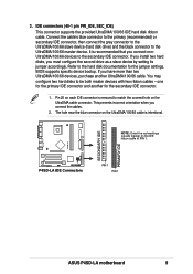
... cable to the secondary IDE connector. one for the primary IDE connector and another UltraDMA/100/66 cable. P4SD-LA SECONDARY IDE PRIMARY IDE P4SD-LA IDE Connectors PIN 1 PIN 1 ASUS P4SD-LA motherboard 9 You may configure two hard disks to match the covered hole on the UltraDMA/100/66 cable is .../100/66 slave device (hard disk drive) and the black connector to the hard disk documentation for the secondary IDE connector. 1. BIOS supports specific device bootup. 3. IDE connectors (40-1 pin PRI_IDE, SEC_IDE) This connector supports the provided UltraDMA/100/66 IDE hard disk ribbon ...
... cable to the secondary IDE connector. one for the primary IDE connector and another UltraDMA/100/66 cable. P4SD-LA SECONDARY IDE PRIMARY IDE P4SD-LA IDE Connectors PIN 1 PIN 1 ASUS P4SD-LA motherboard 9 You may configure two hard disks to match the covered hole on the UltraDMA/100/66 cable is .../100/66 slave device (hard disk drive) and the black connector to the hard disk documentation for the secondary IDE connector. 1. BIOS supports specific device bootup. 3. IDE connectors (40-1 pin PRI_IDE, SEC_IDE) This connector supports the provided UltraDMA/100/66 IDE hard disk ribbon ...
User Guide
Page 18
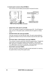
... LED Lead (3-1 pin PLED) This 3-1 pin connector connects to the case-mounted reset switch for rebooting the system without turning off the system power. 14 ASUS P4SD-LA motherboard The read or write activities of the device connected to the any of IDE connectors cause the IDE LED to light up when you turn... on the BIOS or OS settings. Pressing the power switch while in sleep mode. • Hard Disk Activity LED Lead (2-pin HDLED) This 2-pin connector is for more...
... LED Lead (3-1 pin PLED) This 3-1 pin connector connects to the case-mounted reset switch for rebooting the system without turning off the system power. 14 ASUS P4SD-LA motherboard The read or write activities of the device connected to the any of IDE connectors cause the IDE LED to light up when you turn... on the BIOS or OS settings. Pressing the power switch while in sleep mode. • Hard Disk Activity LED Lead (2-pin HDLED) This 2-pin connector is for more...


