Motherboard DIY Troubleshooting Guide
Page 1
® P4S8X Motherboard
® P4S8X Motherboard
P4S8X User Manual
Page 1
Motherboard ® P4S8X User Manual
Motherboard ® P4S8X User Manual
P4S8X User Manual
Page 3
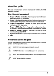
...iii Features About this guide is organized • Chapter 1: Product introduction. Describes the power up sequence with information on the motherboard support CD ROM. • Appendix and Glossary. CAUTION! Information that you MUST follow to change system settings using onboard ...Chapter 4: BIOS setup. Information to prevent damage to yourself. How this guide This user manual contains complete information for installing the ASUS P4S8X motherboard. A summary of product features and special attributes of the BIOS parameters are supplied. • Chapter 5: Software support. WARNING!...
...iii Features About this guide is organized • Chapter 1: Product introduction. Describes the power up sequence with information on the motherboard support CD ROM. • Appendix and Glossary. CAUTION! Information that you MUST follow to change system settings using onboard ...Chapter 4: BIOS setup. Information to prevent damage to yourself. How this guide This user manual contains complete information for installing the ASUS P4S8X motherboard. A summary of product features and special attributes of the BIOS parameters are supplied. • Chapter 5: Software support. WARNING!...
P4S8X User Manual
Page 4
... iii Conventions used in this guide iii Safety information vi FCC/CDC statements vii ASUS contact information viii Chapter 1: Product introduction 1 Welcome 1 1.1 Package contents 1 1.2 Core Specifications 2 1.3 Special Features 3 1.4 Motherboard Components 4 1.4.1 Component Locations 5 1.5 Value-added Solutions 6 Chapter 2: Hardware information 7 2.1 Motherboard installation 7 2.2 Motherboard layout 8 2.3 Before you proceed 10 2.4 Central Processing Unit (CPU 11 2.5 System memory 17...
... iii Conventions used in this guide iii Safety information vi FCC/CDC statements vii ASUS contact information viii Chapter 1: Product introduction 1 Welcome 1 1.1 Package contents 1 1.2 Core Specifications 2 1.3 Special Features 3 1.4 Motherboard Components 4 1.4.1 Component Locations 5 1.5 Value-added Solutions 6 Chapter 2: Hardware information 7 2.1 Motherboard installation 7 2.2 Motherboard layout 8 2.3 Before you proceed 10 2.4 Central Processing Unit (CPU 11 2.5 System memory 17...
P4S8X User Manual
Page 5
... Chapter 5: Software support 81 5.1 Install an operating system 81 5.2 Support CD information 81 5.3 P4S8X Motherboard Support CD 82 5.4 Using the Promise Chip for RAID 0 or 1 84 5.5 Manual Installation of IDE/RAID Drivers 92 5.6 ASUS PC Probe 94 5.7 ASUS Live Update 99 5.8 ASUS MyLogo 100 5.9 3Deep Color Tuner 102 5.10 Winbond Voice Editor 104 5.11 Winbond...
... Chapter 5: Software support 81 5.1 Install an operating system 81 5.2 Support CD information 81 5.3 P4S8X Motherboard Support CD 82 5.4 Using the Promise Chip for RAID 0 or 1 84 5.5 Manual Installation of IDE/RAID Drivers 92 5.6 ASUS PC Probe 94 5.7 ASUS Live Update 99 5.8 ASUS MyLogo 100 5.9 3Deep Color Tuner 102 5.10 Winbond Voice Editor 104 5.11 Winbond...
P4S8X User Manual
Page 6
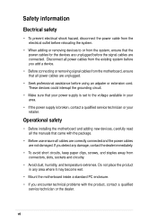
...or extension cord. Disconnect all power cables from the existing system before you add a device. • Before connecting or removing signal cables from the motherboard, ensure that came with the product, contact a qualified service technician or the dealer. Operational safety • Before installing the... motherboard and adding new devices, carefully read all the manuals that all cables are correctly connected and the power cables are not damaged. vi ...
...or extension cord. Disconnect all power cables from the existing system before you add a device. • Before connecting or removing signal cables from the motherboard, ensure that came with the product, contact a qualified service technician or the dealer. Operational safety • Before installing the... motherboard and adding new devices, carefully read all the manuals that all cables are correctly connected and the power cables are not damaged. vi ...

P4S8X User Manual
Page 10
ASUS P4S8X motherboard
ASUS P4S8X motherboard
P4S8X User Manual
Page 11
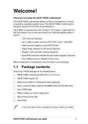
...easy system upgrade (Optional) ~ Four USB ports plus a headers for two more Before installing the motherboard, check the items in your package: 1.1 Package contents Check your retailer. The P4S8X incorporates the Intel® Pentium® 4 Processor coupled with the SiS 648 chipset to set ...pin conductor ribbon cable for UltraDMA/33/66/100/133 IDE drives 9 pin COM2 cable Ribbon cable for buying the ASUS® P4S8X motherboard! ASUS P4S8X motherboard user guide 1 The ASUS P4S8X motherboard delivers a host of new features to 3GB of system memory of the above items is the prime choice for ...
...easy system upgrade (Optional) ~ Four USB ports plus a headers for two more Before installing the motherboard, check the items in your package: 1.1 Package contents Check your retailer. The P4S8X incorporates the Intel® Pentium® 4 Processor coupled with the SiS 648 chipset to set ...pin conductor ribbon cable for UltraDMA/33/66/100/133 IDE drives 9 pin COM2 cable Ribbon cable for buying the ASUS® P4S8X motherboard! ASUS P4S8X motherboard user guide 1 The ASUS P4S8X motherboard delivers a host of new features to 3GB of system memory of the above items is the prime choice for ...
P4S8X User Manual
Page 12
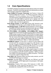
...8XSlot, four USB ports, one COM port, one parallel port with two connectors that support four IDE devices on two channels. This ASUS motherboard represents the latest advances to the Infrared Module for burst mode data transfer rates up to 3GB of I/O functions. Multi-I /O ... performance by executing two actions per clock cycle, supplying data transfer rates up to the highest standards. 1.2 Core Specifications The P4S8X motherboard is designed and assembled according to 133MB/ sec, and USB controller with the highest bandwidth and lowest latency currently available. UltraDMA133...
...8XSlot, four USB ports, one COM port, one parallel port with two connectors that support four IDE devices on two channels. This ASUS motherboard represents the latest advances to the Infrared Module for burst mode data transfer rates up to 3GB of I/O functions. Multi-I /O ... performance by executing two actions per clock cycle, supplying data transfer rates up to the highest standards. 1.2 Core Specifications The P4S8X motherboard is designed and assembled according to 133MB/ sec, and USB controller with the highest bandwidth and lowest latency currently available. UltraDMA133...
P4S8X User Manual
Page 13
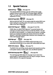
...speaker, messages inform you can easily update the system BIOS even before loading the operating system. ASUS MyLogo™ (See page 100.) This new feature present in the P4S8X motherboard helps you to personalize and add style to use a DOS-based utility or boot from ...patented ASUS technology uses the existing power supply instead of having to provide friendly voice messages and alerts during the Power-On Self-Test (POST). ASUS Multi-language BIOS (See page 59.) The multi-language BIOS offers the language of your system with customizable boot logos. ASUS P4S8X motherboard user...
...speaker, messages inform you can easily update the system BIOS even before loading the operating system. ASUS MyLogo™ (See page 100.) This new feature present in the P4S8X motherboard helps you to personalize and add style to use a DOS-based utility or boot from ...patented ASUS technology uses the existing power supply instead of having to provide friendly voice messages and alerts during the Power-On Self-Test (POST). ASUS Multi-language BIOS (See page 59.) The multi-language BIOS offers the language of your system with customizable boot logos. ASUS P4S8X motherboard user...
P4S8X User Manual
Page 14
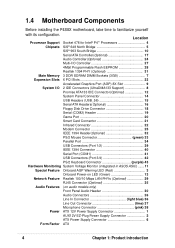
... Connector 40 Serial Port (COM1 41 USB Connectors (Port 3/4 42 PS/2 Keyboard Connector purple) 43 Hardware Monitoring System Voltage Monitor (integrated in ASUS ASIC) ....... 11 Special Feature Onboard AGP Warning LED (Red 3 Onboard Power-on LED (Green 13 Network Feature Realtek 100/10 Mbps LAN PHYs...12V Power Supply Connector 1 AUX12V EZ-Plug Power Supply Connector 2 ATX Power Supply Connector 6 Form Factor ATX 4 Chapter 1: Product introduction 1.4 Motherboard Components Before installing the P4S8X motherboard, take time to familiarize yourself with its configuration.
... Connector 40 Serial Port (COM1 41 USB Connectors (Port 3/4 42 PS/2 Keyboard Connector purple) 43 Hardware Monitoring System Voltage Monitor (integrated in ASUS ASIC) ....... 11 Special Feature Onboard AGP Warning LED (Red 3 Onboard Power-on LED (Green 13 Network Feature Realtek 100/10 Mbps LAN PHYs...12V Power Supply Connector 1 AUX12V EZ-Plug Power Supply Connector 2 ATX Power Supply Connector 6 Form Factor ATX 4 Chapter 1: Product introduction 1.4 Motherboard Components Before installing the P4S8X motherboard, take time to familiarize yourself with its configuration.
P4S8X User Manual
Page 16
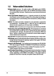
...Push the power button for operating systems that support OS Direct Power Management (OSPM). If the power button is monitored by the ASUS ASIC through the CPU's internal thermal diode to support 10BASE-T/100BASE-TX Fast Ethernet networking. 1.5 Value-added Solutions Software Audio(Optional...with 1.1 USB, the new 2.0 USB protocol delivers transfer speeds up to 40 times faster at 480Mb/s. Onboard LAN (Optional): The motherboard incorporates the RTL8201BL PHY chip to prevent overheating and damage. Temperature, Fan and Voltage Monitoring: CPU temperature is pressed for more Energy ...
...Push the power button for operating systems that support OS Direct Power Management (OSPM). If the power button is monitored by the ASUS ASIC through the CPU's internal thermal diode to support 10BASE-T/100BASE-TX Fast Ethernet networking. 1.5 Value-added Solutions Software Audio(Optional...with 1.1 USB, the new 2.0 USB protocol delivers transfer speeds up to 40 times faster at 480Mb/s. Onboard LAN (Optional): The motherboard incorporates the RTL8201BL PHY chip to prevent overheating and damage. Temperature, Fan and Voltage Monitoring: CPU temperature is pressed for more Energy ...

P4S8X User Manual
Page 18
ASUS P4S8X motherboard
ASUS P4S8X motherboard
P4S8X User Manual
Page 19
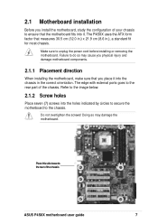
...12.0 in.) x 21.9 cm (8.6 in the correct orientation. Do not overtighten the screws! The P4S8X uses the ATX form factor that the motherboard fits into it into the holes indicated by circles to secure the motherboard to the chassis. Refer to the image below. 2.1.2 Screw holes Place seven (7) screws into the .... Place this side towards the rear of the chassis. The edge with external ports goes to the rear part of the chassis ASUS P4S8X motherboard user guide 7 2.1 Motherboard installation Before you place it . Failure to unplug the power cord before installing or removing the...
...12.0 in.) x 21.9 cm (8.6 in the correct orientation. Do not overtighten the screws! The P4S8X uses the ATX form factor that the motherboard fits into it into the holes indicated by circles to secure the motherboard to the chassis. Refer to the image below. 2.1.2 Screw holes Place seven (7) screws into the .... Place this side towards the rear of the chassis. The edge with external ports goes to the rear part of the chassis ASUS P4S8X motherboard user guide 7 2.1 Motherboard installation Before you place it . Failure to unplug the power cord before installing or removing the...
P4S8X User Manual
Page 20
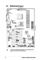
...:Mic In FP_LO_SWL IEEE1394_2 REALTEK AGP_WARN SiS648 HOST/ Memory Controller REALTEK Accelerated Graphics Port AGP 01 23 45 FP_AUDIO FP_LO_SWR 4MB ISA PCI1 P4S8X PCI2 SMART I/O AUX MODEM CD C-Media 6CH Codec SPDIF PCI3 PCI4 ® PCI5 IR_CON SMARTCON GAME PCI6 COM2 FLOPPY SiS963 MuTLOL... SPEECH USBPWR_56 CHA_FAN SB_PWR USB_56 IDE_LED PANEL The audio and LAN features are grayed out in the above motherboard layout. PROMISE PDC20376 Controller ASUS ASIC with Hardware Monitor CHASSIS SMB PRI_ATA133 8 Chapter 2: Hardware information These components are optional.
...:Mic In FP_LO_SWL IEEE1394_2 REALTEK AGP_WARN SiS648 HOST/ Memory Controller REALTEK Accelerated Graphics Port AGP 01 23 45 FP_AUDIO FP_LO_SWR 4MB ISA PCI1 P4S8X PCI2 SMART I/O AUX MODEM CD C-Media 6CH Codec SPDIF PCI3 PCI4 ® PCI5 IR_CON SMARTCON GAME PCI6 COM2 FLOPPY SiS963 MuTLOL... SPEECH USBPWR_56 CHA_FAN SB_PWR USB_56 IDE_LED PANEL The audio and LAN features are grayed out in the above motherboard layout. PROMISE PDC20376 Controller ASUS ASIC with Hardware Monitor CHASSIS SMB PRI_ATA133 8 Chapter 2: Hardware information These components are optional.
P4S8X User Manual
Page 21
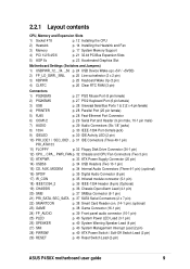
... p. 14 Installing the Heatsink and Fan 3) Memory p. 17 System Memory Support 4) PCI 1/2/3/4/5/6 p. 21 32-bit PCI Bus Expansion Slots 5) AGP 8x p. 23 Accelerated Graphics Slot Motherboard Settings (Switches and Jumpers) 1) USBPWR_12, _34, _56 p. 24 USB Device Wake-up (+5V / +5VSB) 2) FP_LO_SWR,_SWL p. 25 Line out selector (2 x 2 pin) 3) KBPWR p. 25 Keyboard Wake...) SMI p. 40 System Management Interrupt Lead (2 pin) 28) PWRSW p. 40 ATX Power Switch / Soft-Off Switch Lead (2 pin) 29) RESET p. 40 Reset Switch Lead (2-pin) ASUS P4S8X motherboard user guide 9
... p. 14 Installing the Heatsink and Fan 3) Memory p. 17 System Memory Support 4) PCI 1/2/3/4/5/6 p. 21 32-bit PCI Bus Expansion Slots 5) AGP 8x p. 23 Accelerated Graphics Slot Motherboard Settings (Switches and Jumpers) 1) USBPWR_12, _34, _56 p. 24 USB Device Wake-up (+5V / +5VSB) 2) FP_LO_SWR,_SWL p. 25 Line out selector (2 x 2 pin) 3) KBPWR p. 25 Keyboard Wake...) SMI p. 40 System Management Interrupt Lead (2 pin) 28) PWRSW p. 40 ATX Power Switch / Soft-Off Switch Lead (2 pin) 29) RESET p. 40 Reset Switch Lead (2-pin) ASUS P4S8X motherboard user guide 9
P4S8X User Manual
Page 22
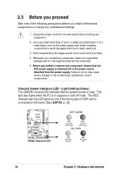
2.3 Before you proceed Take note of AGP card is connected to the board: (See AGP 8X, p. 23) P4S8X ® P4S8X Onboard LED AGP_WARN ON Incorrect AGP Card OFF Correct AGP Card SB_PWR ON Standby Power OFF Powered Off 10 Chapter 2: Hardware information... the wrong type of the following precautions before you uninstall any component, ensure that the ATX power supply is switched off mode. Whenever you install motherboard components or change any component. 2. Onboard System Indicators (LED - Light Emitting Diodes) The GREEN onboard LED indicates that came with the component. 5. Use...
2.3 Before you proceed Take note of AGP card is connected to the board: (See AGP 8X, p. 23) P4S8X ® P4S8X Onboard LED AGP_WARN ON Incorrect AGP Card OFF Correct AGP Card SB_PWR ON Standby Power OFF Powered Off 10 Chapter 2: Hardware information... the wrong type of the following precautions before you uninstall any component, ensure that the ATX power supply is switched off mode. Whenever you install motherboard components or change any component. 2. Onboard System Indicators (LED - Light Emitting Diodes) The GREEN onboard LED indicates that came with the component. 5. Use...
P4S8X User Manual
Page 23
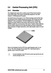
... for the Intel® Pentium® 4 478/Northwood Processor. Incorrect installation of 3.2 and 4.2GB/s. 2.4 Central Processing Unit (CPU) 2.4.1 Overview The motherboard comes with a surface mount 478-pin Zero Insertion Force (ZIF) socket. The Intel NetBurst micro-architecture features the hyper-pipelined technology, rapid execution engine, ..., and a data transfer rates of the CPU into the socket may bend the pins and severely damage the CPU! ASUS P4S8X motherboard user guide 11 This mark indicates the processor Pin 1 that the CPU has a gold triangular mark on one corner.
... for the Intel® Pentium® 4 478/Northwood Processor. Incorrect installation of 3.2 and 4.2GB/s. 2.4 Central Processing Unit (CPU) 2.4.1 Overview The motherboard comes with a surface mount 478-pin Zero Insertion Force (ZIF) socket. The Intel NetBurst micro-architecture features the hyper-pipelined technology, rapid execution engine, ..., and a data transfer rates of the CPU into the socket may bend the pins and severely damage the CPU! ASUS P4S8X motherboard user guide 11 This mark indicates the processor Pin 1 that the CPU has a gold triangular mark on one corner.
P4S8X User Manual
Page 24
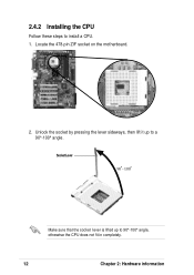
Locate the 478-pin ZIF socket on the motherboard. 2. Unlock the socket by pressing the lever sideways, then lift it up to a 90°-100° angle. Socket Lever 90 - 100 Make sure that the socket lever is lifted up to 90°-100° angle, otherwise the CPU does not fit in completely. 12 Chapter 2: Hardware information 2.4.2 Installing the CPU Follow these steps to install a CPU. 1.
Locate the 478-pin ZIF socket on the motherboard. 2. Unlock the socket by pressing the lever sideways, then lift it up to a 90°-100° angle. Socket Lever 90 - 100 Make sure that the socket lever is lifted up to 90°-100° angle, otherwise the CPU does not fit in completely. 12 Chapter 2: Hardware information 2.4.2 Installing the CPU Follow these steps to install a CPU. 1.
P4S8X User Manual
Page 25
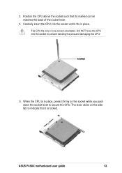
Gold Mark 5. ASUS P4S8X motherboard user guide 13 The CPU fits only in place. DO NOT force the CPU into the socket until it firmly on the side tab to prevent bending the pins and damaging the CPU! The lever clicks on the socket while you push down the socket lever to secure the CPU. Position the CPU above the socket such that it is in place, press it fits in one correct orientation. Carefully insert the CPU into the socket to indicate that its marked corner matches the base of the socket lever. 4. When the CPU is locked. 3.
Gold Mark 5. ASUS P4S8X motherboard user guide 13 The CPU fits only in place. DO NOT force the CPU into the socket until it firmly on the side tab to prevent bending the pins and damaging the CPU! The lever clicks on the socket while you push down the socket lever to secure the CPU. Position the CPU above the socket such that it is in place, press it fits in one correct orientation. Carefully insert the CPU into the socket to indicate that its marked corner matches the base of the socket lever. 4. When the CPU is locked. 3.


