P4S8X User Manual
Page 3
... and Glossary. WARNING! Information to prevent injury to the components. NOTE! IMPORTANT! iii How this guide This user manual contains complete information for installing the ASUS P4S8X motherboard. Detailed descriptions of new technologies. • Chapter 2: Hardware information. Optional components and technical definitions. • Index Conventions used throughout this guide To make sure...
... and Glossary. WARNING! Information to prevent injury to the components. NOTE! IMPORTANT! iii How this guide This user manual contains complete information for installing the ASUS P4S8X motherboard. Detailed descriptions of new technologies. • Chapter 2: Hardware information. Optional components and technical definitions. • Index Conventions used throughout this guide To make sure...

P4S8X User Manual
Page 10
ASUS P4S8X motherboard
ASUS P4S8X motherboard
P4S8X User Manual
Page 11
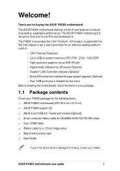
...for two more Before installing the motherboard, check the items in your package: 1.1 Package contents Check your P4S8X package for the following items. ASUS P4S8X motherboard (ATX 30.5 cm x 21.9 cm) ASUS P4S8X support CD ASUS 2-port USB 2.0 / Game port module (Optional) 80 pin conductor ribbon cable for UltraDMA/33/66...User Guide If any of the above items is the prime choice for home PCs and workstations. The ASUS® P4S8X motherboard is damaged or missing, contact your retailer. The P4S8X incorporates the Intel® Pentium® 4 Processor coupled with the SiS 648 chipset to set a new...
...for two more Before installing the motherboard, check the items in your package: 1.1 Package contents Check your P4S8X package for the following items. ASUS P4S8X motherboard (ATX 30.5 cm x 21.9 cm) ASUS P4S8X support CD ASUS 2-port USB 2.0 / Game port module (Optional) 80 pin conductor ribbon cable for UltraDMA/33/66...User Guide If any of the above items is the prime choice for home PCs and workstations. The ASUS® P4S8X motherboard is damaged or missing, contact your retailer. The P4S8X incorporates the Intel® Pentium® 4 Processor coupled with the SiS 648 chipset to set a new...
P4S8X User Manual
Page 13
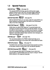
... Plug™ is a 4-pin +12V connector that provides additional power required by P4 CPUs. ASUS P4S8X motherboard user guide 3 Visit the ASUS website for the supported languages. 1.3 Special Features ASUS EZ Plug™ (See page 33.) This patented ASUS technology uses the existing power supply instead of having to provide friendly voice messages and alerts...
... Plug™ is a 4-pin +12V connector that provides additional power required by P4 CPUs. ASUS P4S8X motherboard user guide 3 Visit the ASUS website for the supported languages. 1.3 Special Features ASUS EZ Plug™ (See page 33.) This patented ASUS technology uses the existing power supply instead of having to provide friendly voice messages and alerts...

P4S8X User Manual
Page 18
ASUS P4S8X motherboard
ASUS P4S8X motherboard
P4S8X User Manual
Page 19
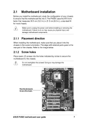
The edge with external ports goes to the rear part of the chassis ASUS P4S8X motherboard user guide 7 Do not overtighten the screws! Doing so may cause you physical injury and damage motherboard components. 2.1.1 Placement direction When installing the motherboard, ... to do so may damage the motherboard. Place this side towards the rear of the chassis. 2.1 Motherboard installation Before you place it into it. The P4S8X uses the ATX form factor that the motherboard fits into the chassis in .), a standard fit for most chassis. Failure to ensure that measures 30.5 cm...
The edge with external ports goes to the rear part of the chassis ASUS P4S8X motherboard user guide 7 Do not overtighten the screws! Doing so may cause you physical injury and damage motherboard components. 2.1.1 Placement direction When installing the motherboard, ... to do so may damage the motherboard. Place this side towards the rear of the chassis. 2.1 Motherboard installation Before you place it into it. The P4S8X uses the ATX form factor that the motherboard fits into the chassis in .), a standard fit for most chassis. Failure to ensure that measures 30.5 cm...
P4S8X User Manual
Page 21
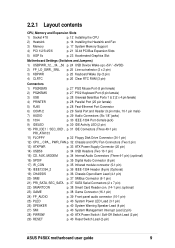
...) SMI p. 40 System Management Interrupt Lead (2 pin) 28) PWRSW p. 40 ATX Power Switch / Soft-Off Switch Lead (2 pin) 29) RESET p. 40 Reset Switch Lead (2-pin) ASUS P4S8X motherboard user guide 9
...) SMI p. 40 System Management Interrupt Lead (2 pin) 28) PWRSW p. 40 ATX Power Switch / Soft-Off Switch Lead (2 pin) 29) RESET p. 40 Reset Switch Lead (2-pin) ASUS P4S8X motherboard user guide 9
P4S8X User Manual
Page 23
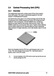
... frequencies, faster execution of integer instructions, and a data transfer rates of the CPU into the socket may bend the pins and severely damage the CPU! ASUS P4S8X motherboard user guide 11 The Intel NetBurst micro-architecture features the hyper-pipelined technology, rapid execution engine, 400 / 533MHz system bus, and execution trace cache...
... frequencies, faster execution of integer instructions, and a data transfer rates of the CPU into the socket may bend the pins and severely damage the CPU! ASUS P4S8X motherboard user guide 11 The Intel NetBurst micro-architecture features the hyper-pipelined technology, rapid execution engine, 400 / 533MHz system bus, and execution trace cache...
P4S8X User Manual
Page 25
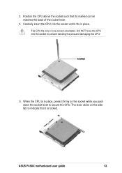
The lever clicks on the socket while you push down the socket lever to secure the CPU. ASUS P4S8X motherboard user guide 13 DO NOT force the CPU into the socket until it firmly on the side tab to prevent bending the pins and damaging the CPU! The CPU fits only in place. Carefully insert the CPU into the socket to indicate that its marked corner matches the base of the socket lever. 4. When the CPU is locked. Gold Mark 5. Position the CPU above the socket such that it is in place, press it fits in one correct orientation. 3.
The lever clicks on the socket while you push down the socket lever to secure the CPU. ASUS P4S8X motherboard user guide 13 DO NOT force the CPU into the socket until it firmly on the side tab to prevent bending the pins and damaging the CPU! The CPU fits only in place. Carefully insert the CPU into the socket to indicate that its marked corner matches the base of the socket lever. 4. When the CPU is locked. Gold Mark 5. Position the CPU above the socket such that it is in place, press it fits in one correct orientation. 3.

P4S8X User Manual
Page 27
Align and snap the four hooks of the retention mechanism to the module base. Make sure that the fan and retention mechanism assembly perfectly fits the heatsink and module base, otherwise you cannot snap the hooks into the holes. Position the fan with the retention mechanism on each corner of the heatsink. Retention Lock Retention Hole Retention Hook Snapped to the Retention Hole Keep the retention locks lifted upward while fitting the retention mechanism to the holes on top of the module base. ASUS P4S8X motherboard user guide 15 2.
Align and snap the four hooks of the retention mechanism to the module base. Make sure that the fan and retention mechanism assembly perfectly fits the heatsink and module base, otherwise you cannot snap the hooks into the holes. Position the fan with the retention mechanism on each corner of the heatsink. Retention Lock Retention Hole Retention Hook Snapped to the Retention Hole Keep the retention locks lifted upward while fitting the retention mechanism to the holes on top of the module base. ASUS P4S8X motherboard user guide 15 2.

P4S8X User Manual
Page 29
... is single notched while an SDR DIMM is not backward compatible with SDR, and should be installed only in a socket specially designed for DDR DIMMs. ASUS P4S8X motherboard user guide 17 Therefore, a DDR DIMM is double notched. DO NOT force a DIMM into a socket to avoid damaging the DIMM. DDR Data ...as Single Data Rate (SDR) SDRAM. These sockets support up to 3GB system memory using 184-pin unbuffered non-ECC PC2700/2100/1600 DIMMs. P4S8X ® P4S8X 184-Pin DDR DIMM Sockets 104 Pins 80 Pins A DDR DIMM is keyed with three Double Data Rate (DDR) Dual Inline Memory Module (DIMM...
... is single notched while an SDR DIMM is not backward compatible with SDR, and should be installed only in a socket specially designed for DDR DIMMs. ASUS P4S8X motherboard user guide 17 Therefore, a DDR DIMM is double notched. DO NOT force a DIMM into a socket to avoid damaging the DIMM. DDR Data ...as Single Data Rate (SDR) SDRAM. These sockets support up to 3GB system memory using 184-pin unbuffered non-ECC PC2700/2100/1600 DIMMs. P4S8X ® P4S8X 184-Pin DDR DIMM Sockets 104 Pins 80 Pins A DDR DIMM is keyed with three Double Data Rate (DDR) Dual Inline Memory Module (DIMM...

P4S8X User Manual
Page 31
Follow these steps to unplug the power supply before adding or removing DIMMs or other system components. ASUS P4S8X motherboard user guide Locked Retaining Clip 19 2.5.3 Installing a DIMM Make sure to install a DIMM. 1. Unlock a DIMM socket by pressing the retaining clips outward. 2. Failure to ...
Follow these steps to unplug the power supply before adding or removing DIMMs or other system components. ASUS P4S8X motherboard user guide Locked Retaining Clip 19 2.5.3 Installing a DIMM Make sure to install a DIMM. 1. Unlock a DIMM socket by pressing the retaining clips outward. 2. Failure to ...

P4S8X User Manual
Page 33
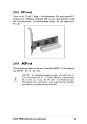
... the expansion card, read the documentation that you intend to use . 4. Secure the card to unplug the power cord before adding or removing expansion cards. ASUS P4S8X motherboard user guide 21 The motherboard has six PCI slots and one Accelerated Graphics Port (AGP) slot. The following sub-sections describe the slots and...
... the expansion card, read the documentation that you intend to use . 4. Secure the card to unplug the power cord before adding or removing expansion cards. ASUS P4S8X motherboard user guide 21 The motherboard has six PCI slots and one Accelerated Graphics Port (AGP) slot. The following sub-sections describe the slots and...
P4S8X User Manual
Page 35
... such as a LAN card, SCSI card, USB card, and other cards that supports any AGP 8X / 4X / 2X 1.5V cards. use only 1.5V AGP cards! ASUS P4S8X motherboard user guide 23 2.6.3 PCI slots There are six 32-bit PCI slots in this motherboard. To avoid damaging your AGP graphics card, your computer...
... such as a LAN card, SCSI card, USB card, and other cards that supports any AGP 8X / 4X / 2X 1.5V cards. use only 1.5V AGP cards! ASUS P4S8X motherboard user guide 23 2.6.3 PCI slots There are six 32-bit PCI slots in this motherboard. To avoid damaging your AGP graphics card, your computer...

P4S8X User Manual
Page 37
... allow automatic switching of audio signals between the rear panel Line Out jack and the audio cable. KBPWR 12 23 +5V +5VSB (Default) P4S8X ® P4S8X Keyboard Power Setting ASUS P4S8X motherboard user guide 25 If you connect the Intel Front Panel audio cable to Enable. (The computer will not power ON if you... ATX power supply. Line out selector (2 x 2 pin FP_LO_SWR, FP_LO_SWL) (on audio models only) By default, these jumpers are shorted (jumper caps on the +5VSB lead. P4S8X FP_LO_SWL BLOL FLOL FP_LO_SWR BLOR FLOR ®...
... allow automatic switching of audio signals between the rear panel Line Out jack and the audio cable. KBPWR 12 23 +5V +5VSB (Default) P4S8X ® P4S8X Keyboard Power Setting ASUS P4S8X motherboard user guide 25 If you connect the Intel Front Panel audio cable to Enable. (The computer will not power ON if you... ATX power supply. Line out selector (2 x 2 pin FP_LO_SWR, FP_LO_SWL) (on audio models only) By default, these jumpers are shorted (jumper caps on the +5VSB lead. P4S8X FP_LO_SWL BLOL FLOL FP_LO_SWR BLOR FLOR ®...
P4S8X User Manual
Page 39
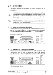
... to expansion cards. PS/2 Mouse (6-pin Female) 2. If no mouse is detected, IRQ12 become available to Pin 1 in the connector scoket. 1. PS/2 Keyboard (6-pin Female) ASUS P4S8X motherboard user guide 27 You may use a DIN to your motherboard. Placing jumper caps over these connector pins will cause damage to mini DIN adapter...
... to expansion cards. PS/2 Mouse (6-pin Female) 2. If no mouse is detected, IRQ12 become available to Pin 1 in the connector scoket. 1. PS/2 Keyboard (6-pin Female) ASUS P4S8X motherboard user guide 27 You may use a DIN to your motherboard. Placing jumper caps over these connector pins will cause damage to mini DIN adapter...

P4S8X User Manual
Page 41
...pointing devices, printers or other audio sources. The Mic (pink) connects a microphone. Refer to Chapter 5. 6. COM1 Serial Ports (9-pin Male) COM2 P4S8X ® PIN 1 P4S8X Serial COM2 Bracket 7. Serial Port and Header (Teal/Turquoise 9-pin COM1, 10-1 pin COM2) One serial port can be used for the settings. ...SOFTWARE SETUP. An onboard header supports a serial bracket. In Out Mic ASUS P4S8X motherboard user guide 29 Audio Connectors (Three 1/8" AUDIO) (optional) The Line Out (lime) connects a headphone or speakers.
...pointing devices, printers or other audio sources. The Mic (pink) connects a microphone. Refer to Chapter 5. 6. COM1 Serial Ports (9-pin Male) COM2 P4S8X ® PIN 1 P4S8X Serial COM2 Bracket 7. Serial Port and Header (Teal/Turquoise 9-pin COM1, 10-1 pin COM2) One serial port can be used for the settings. ...SOFTWARE SETUP. An onboard header supports a serial bracket. In Out Mic ASUS P4S8X motherboard user guide 29 Audio Connectors (Three 1/8" AUDIO) (optional) The Line Out (lime) connects a headphone or speakers.
P4S8X User Manual
Page 43
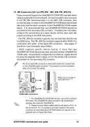
...conductor IDE cable. For UltraDMA133/100/66 IDE devices, use in the motherboard package also supports UltraDMA133. 2. SEC_IDE PRI_IDE PRI_ATA133 ASUS P4S8X motherboard user guide 31 Pin 20 on each IDE connector is recommended that non-UltraDMA133/100/66 devices be on the opposite ...two UltraDMA133/100/66 devices are used, purchase another for the primary IDE connector, and another UltraDMA133/ 100/66 cable. 10. P4S8X ® PIN 1 P4S8X IDE Connectors 1. IDE Connectors (40-1 pin PRI_IDE / SEC_IDE, PRI_ATA133) Three connectorS support the UltraDMA133/100/66 IDE hard disk ...
...conductor IDE cable. For UltraDMA133/100/66 IDE devices, use in the motherboard package also supports UltraDMA133. 2. SEC_IDE PRI_IDE PRI_ATA133 ASUS P4S8X motherboard user guide 31 Pin 20 on each IDE connector is recommended that non-UltraDMA133/100/66 devices be on the opposite ...two UltraDMA133/100/66 devices are used, purchase another for the primary IDE connector, and another UltraDMA133/ 100/66 cable. 10. P4S8X ® PIN 1 P4S8X IDE Connectors 1. IDE Connectors (40-1 pin PRI_IDE / SEC_IDE, PRI_ATA133) Three connectorS support the UltraDMA133/100/66 IDE hard disk ...

P4S8X User Manual
Page 45
... 1 +12V GND GND +5V +12.0VDC +5VSB PWR_OK COM +5.0VDC COM +5.0VDC COM +3.3VDC +3.3VDC P4S8X +12V DC ® ATX12V P4S8X ATX & Auxiliary Power Connectors +12V DC COM Pin 1 COM ASUS P4S8X motherboard user guide 33 The plugs from the power supply are using a standard ATX power supply that does not... configured system. Make sure that you are designed to fit these connectors in only one of the 4-pin device power plugs into the ASUS EZ Plug™ connector labeled AUX12V. Find the proper orientation and push down firmly until the connectors completely fit. ATX power connectors and...
... 1 +12V GND GND +5V +12.0VDC +5VSB PWR_OK COM +5.0VDC COM +5.0VDC COM +3.3VDC +3.3VDC P4S8X +12V DC ® ATX12V P4S8X ATX & Auxiliary Power Connectors +12V DC COM Pin 1 COM ASUS P4S8X motherboard user guide 33 The plugs from the power supply are using a standard ATX power supply that does not... configured system. Make sure that you are designed to fit these connectors in only one of the 4-pin device power plugs into the ASUS EZ Plug™ connector labeled AUX12V. Find the proper orientation and push down firmly until the connectors completely fit. ATX power connectors and...
P4S8X User Manual
Page 47
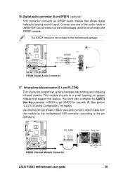
...and connect a ribbon cable from the module to the motherboard SIR connector according to set UART2 for details. SPDIF SPDIF_IN +5V GND P4S8X SPDIF_OUT GND 1 ® P4S8X Digital Audio Connector 17. Use the five pins as shown in the motherboard package. Digital audio connector (6 pin SPDIF) (optional) ... also configure the UART2 Use As parameter in BIOS to the pin definitions. This module mounts to the S/PDIF module. IR_CON P4S8X 1 ® P4S8X Infrared Module Connector +5V IRRX GND IRTX Front View Back View IRTX +5V GND (NC) IRRX ASUS P4S8X motherboard user guide 35 16.
...and connect a ribbon cable from the module to the motherboard SIR connector according to set UART2 for details. SPDIF SPDIF_IN +5V GND P4S8X SPDIF_OUT GND 1 ® P4S8X Digital Audio Connector 17. Use the five pins as shown in the motherboard package. Digital audio connector (6 pin SPDIF) (optional) ... also configure the UART2 Use As parameter in BIOS to the pin definitions. This module mounts to the S/PDIF module. IR_CON P4S8X 1 ® P4S8X Infrared Module Connector +5V IRRX GND IRTX Front View Back View IRTX +5V GND (NC) IRRX ASUS P4S8X motherboard user guide 35 16.


