
Motherboard DIY Troubleshooting Guide
Page 1
Motherboard ® P4S133 User Guide
Motherboard ® P4S133 User Guide

Motherboard DIY Troubleshooting Guide
Page 3
...BIOS firmware. Information that you MUST follow to yourself. Tips and helpful information. iii A summary of contents on the motherboard. • Chapter 3: Powering up. How to the components. Optional components and technical definitions. • Index Conventions...jumpers and connectors on the motherboard support CD ROM. • Appendix and Glossary. Features About this guide is organized • Chapter 1: Product introduction. CAUTION! IMPORTANT! How this guide This user manual contains complete information for installing the ASUS P4S133 motherboard. NOTE!
...BIOS firmware. Information that you MUST follow to yourself. Tips and helpful information. iii A summary of contents on the motherboard. • Chapter 3: Powering up. How to the components. Optional components and technical definitions. • Index Conventions...jumpers and connectors on the motherboard support CD ROM. • Appendix and Glossary. Features About this guide is organized • Chapter 1: Product introduction. CAUTION! IMPORTANT! How this guide This user manual contains complete information for installing the ASUS P4S133 motherboard. NOTE!

Motherboard DIY Troubleshooting Guide
Page 4
... Conventions used in this guide iii Safety information vi FCC/CDC statements vii ASUS contact information viii Chapter 1: Product introduction 1 Welcome 1 1.1 Package contents 1 1.2 Core Specifications 2 1.3 Special Features 3 1.4 Motherboard Components 4 1.4.1 Component Locations 5 Chapter 2: Hardware information 7 2.1 Motherboard installation 7 2.1.1 Placement direction 7 2.1.2 Screw holes 7 2.2 Motherboard layout 8 2.3 Before you proceed 9 2.4 Central Processing Unit (CPU 10 2.4.1 Overview 10 2.4.2 Installing the...
... Conventions used in this guide iii Safety information vi FCC/CDC statements vii ASUS contact information viii Chapter 1: Product introduction 1 Welcome 1 1.1 Package contents 1 1.2 Core Specifications 2 1.3 Special Features 3 1.4 Motherboard Components 4 1.4.1 Component Locations 5 Chapter 2: Hardware information 7 2.1 Motherboard installation 7 2.1.1 Placement direction 7 2.1.2 Screw holes 7 2.2 Motherboard layout 8 2.3 Before you proceed 9 2.4 Central Processing Unit (CPU 10 2.4.1 Overview 10 2.4.2 Installing the...

Motherboard DIY Troubleshooting Guide
Page 5
... Up Control 69 4.5.2 Hardware Monitor 71 4.6 Boot Menu 72 4.7 Exit Menu 74 Chapter 5: Software support 77 5.1 Install an operating system 77 5.2 Support CD information 77 5.3 P4S133 Motherboard Support CD 78 5.4 ASUS PC Probe 80 5.5 ASUS Live Update 85 5.6 3Deep Color Tuner 86 5.7 ITE GSM Editor 88 Glossary 93 Index 97 v
... Up Control 69 4.5.2 Hardware Monitor 71 4.6 Boot Menu 72 4.7 Exit Menu 74 Chapter 5: Software support 77 5.1 Install an operating system 77 5.2 Support CD information 77 5.3 P4S133 Motherboard Support CD 78 5.4 ASUS PC Probe 80 5.5 ASUS Live Update 85 5.6 3Deep Color Tuner 86 5.7 ITE GSM Editor 88 Glossary 93 Index 97 v

Motherboard DIY Troubleshooting Guide
Page 6
... a standard PC enclosure. • If you add a device. • Before connecting or removing signal cables from the motherboard, ensure that all cables are correctly connected and the power cables are not damaged. Do not place the product in your retailer. These ...to or from the system, ensure that came with the product, contact a qualified service technician or the dealer. Operational safety • Before installing the motherboard and adding new devices, carefully read all the manuals that the power cables for the devices are unplugged before the signal cables are connected. vi...
... a standard PC enclosure. • If you add a device. • Before connecting or removing signal cables from the motherboard, ensure that all cables are correctly connected and the power cables are not damaged. Do not place the product in your retailer. These ...to or from the system, ensure that came with the product, contact a qualified service technician or the dealer. Operational safety • Before installing the motherboard and adding new devices, carefully read all the manuals that the power cables for the devices are unplugged before the signal cables are connected. vi...

Motherboard DIY Troubleshooting Guide
Page 10
ASUS P4S133 motherboard
ASUS P4S133 motherboard

Motherboard DIY Troubleshooting Guide
Page 11
... your retailer. The ASUS® P4S133 motherboard is damaged or missing, contact your P4S133 package for the following items. ASUS P4S133 motherboard (ATX form factor: 12-in x 8.6-in) ASUS P4S133 support CD ASUS 2-port USB 1.1 module 80-conductor ribbon cable for UltraDMA/33/66/100 IDE drives 40-conductor IDE cable Ribbon cable for buying the ASUS® P4S133 motherboard! ASUS P4S133 motherboard user guide 1 Thank...
... your retailer. The ASUS® P4S133 motherboard is damaged or missing, contact your P4S133 package for the following items. ASUS P4S133 motherboard (ATX form factor: 12-in x 8.6-in) ASUS P4S133 support CD ASUS 2-port USB 1.1 module 80-conductor ribbon cable for UltraDMA/33/66/100 IDE drives 40-conductor IDE cable Ribbon cable for buying the ASUS® P4S133 motherboard! ASUS P4S133 motherboard user guide 1 Thank...
Motherboard DIY Troubleshooting Guide
Page 12
This ASUS motherboard represents the latest advances and offers users the finest componentry available today... North Bridge Chipset: the SiS® 645 supports AGP 4X/2X mode, 400MHz ... frequency. Connections: Parallel, PS/2 mouse, PS/2 keyboard, 2 USB, RJ45, Microphone, Line In Jack, Line Out Jack, Standard ATX power. 2 Chapter 1: Product introduction 1.2 Core Specifications The P4S133 motherboard is designed and assembled according to 100MB/ sec, and USB controller with three root hubs for audio, video, and Internet applications. The Pentium 4 processor utilizes...
This ASUS motherboard represents the latest advances and offers users the finest componentry available today... North Bridge Chipset: the SiS® 645 supports AGP 4X/2X mode, 400MHz ... frequency. Connections: Parallel, PS/2 mouse, PS/2 keyboard, 2 USB, RJ45, Microphone, Line In Jack, Line Out Jack, Standard ATX power. 2 Chapter 1: Product introduction 1.2 Core Specifications The P4S133 motherboard is designed and assembled according to 100MB/ sec, and USB controller with three root hubs for audio, video, and Internet applications. The Pentium 4 processor utilizes...
Motherboard DIY Troubleshooting Guide
Page 13
All system fans are monitored to ensure stable voltage to critical motherboard components. Onboard LAN (Optional): The motherboard incorporates the Realtek PHY RTL8201 chip to support the cutting-edge technology for operating systems that support OS Direct ...and Voltage Monitoring: CPU temperature is onboard to accommodate the Sony/Philips Digital Interface (S/PDIF) Out module, which supports coaxial and fiber interfaces. ASUS P4S133 motherboard user guide 3 Dual Function Power Button: Push the power button for less than 4 seconds, the system enters the soft-off automatically even...
All system fans are monitored to ensure stable voltage to critical motherboard components. Onboard LAN (Optional): The motherboard incorporates the Realtek PHY RTL8201 chip to support the cutting-edge technology for operating systems that support OS Direct ...and Voltage Monitoring: CPU temperature is onboard to accommodate the Sony/Philips Digital Interface (S/PDIF) Out module, which supports coaxial and fiber interfaces. ASUS P4S133 motherboard user guide 3 Dual Function Power Button: Push the power button for less than 4 seconds, the system enters the soft-off automatically even...

Motherboard DIY Troubleshooting Guide
Page 14
... installing the P4S133 motherboard, take time to familiarize yourself with its configuration: understanding the motherboard makes upgrading easy. Sufficient knowledge of specifications prevents accidental damage. Location Processor Support Socket 478 for Intel® P4™... 4X Slot 25 System I/O 1 Floppy Disk Drive Connector 7 2 IDE Connectors (UltraDMA/100 Support 8 Smart Card Connector (Optional 11 1 Infrared Connector 12 1 ASUS iPanel Connector (Optional 13 1 System Panel Connector 14 USB Headers (USB1, USB2 18 Modem Connector 20 1 Parallel Port 28 2 Serial Ports (COM1/COM2 33...
... installing the P4S133 motherboard, take time to familiarize yourself with its configuration: understanding the motherboard makes upgrading easy. Sufficient knowledge of specifications prevents accidental damage. Location Processor Support Socket 478 for Intel® P4™... 4X Slot 25 System I/O 1 Floppy Disk Drive Connector 7 2 IDE Connectors (UltraDMA/100 Support 8 Smart Card Connector (Optional 11 1 Infrared Connector 12 1 ASUS iPanel Connector (Optional 13 1 System Panel Connector 14 USB Headers (USB1, USB2 18 Modem Connector 20 1 Parallel Port 28 2 Serial Ports (COM1/COM2 33...

Motherboard DIY Troubleshooting Guide
Page 18
ASUS P4S133 motherboard
ASUS P4S133 motherboard

Motherboard DIY Troubleshooting Guide
Page 19
... the screws! Doing so may cause you physical injury and damage motherboard components. 2.1.1 Placement direction When installing the motherboard, make sure that you install the motherboard, study the configuration of the chassis ASUS P4S133 motherboard user guide 7 The P4S133 uses the ATX form factor that the motherboard fits into it into the holes indicated by circles to secure...
... the screws! Doing so may cause you physical injury and damage motherboard components. 2.1.1 Placement direction When installing the motherboard, make sure that you install the motherboard, study the configuration of the chassis ASUS P4S133 motherboard user guide 7 The P4S133 uses the ATX form factor that the motherboard fits into it into the holes indicated by circles to secure...

Motherboard DIY Troubleshooting Guide
Page 20
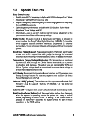
These components are optional. 30.5cm (12.0in) 2.2 Motherboard layout 21.9cm (8.6in) KBPWR1 USBV1 PS/2KBMS T: Mouse B: Keyboard... In LAN PHY Chip SiS645 HOST/ Memory Controller Accelerated Graphics Port AGP CD1 ALIN1 PCI1 IAPANEL1 AUX1 PCI2 P4S133 PC3 ® C-Media CMI8738 6CH Audio Controller BCS1 BCS2 SPDIF1 PCI4 LED1 PCI5 MODEM1 01 23 45... MuTLOL Media I/O JEN1 PWRTMP1 CLRCMOS1 CR2032 3V Lithium Cell CMOS Power Super I/O SMB1 SMARTCON1 IR1 CHASSIS1 ASUS ASIC with Hardware Monitor 2Mbit Firmware Hub CHASFAN1 USB2 USB1 USBV2 USBV3 AFPANEL1 IDELED1 PANEL1 IDE2 IDE1 The...
These components are optional. 30.5cm (12.0in) 2.2 Motherboard layout 21.9cm (8.6in) KBPWR1 USBV1 PS/2KBMS T: Mouse B: Keyboard... In LAN PHY Chip SiS645 HOST/ Memory Controller Accelerated Graphics Port AGP CD1 ALIN1 PCI1 IAPANEL1 AUX1 PCI2 P4S133 PC3 ® C-Media CMI8738 6CH Audio Controller BCS1 BCS2 SPDIF1 PCI4 LED1 PCI5 MODEM1 01 23 45... MuTLOL Media I/O JEN1 PWRTMP1 CLRCMOS1 CR2032 3V Lithium Cell CMOS Power Super I/O SMB1 SMARTCON1 IR1 CHASSIS1 ASUS ASIC with Hardware Monitor 2Mbit Firmware Hub CHASFAN1 USB2 USB1 USBV2 USBV3 AFPANEL1 IDELED1 PANEL1 IDE2 IDE1 The...

Motherboard DIY Troubleshooting Guide
Page 21
...cord from the wall socket before touching any component, place it on them due to static electricity. 3. Failure to do not to the motherboard, peripherals, and/or components. Hold components by the edges and do so may cause severe damage to touch the ICs on a grounded antistatic ...power supply case, before handling components to avoid damaging them . 4. 2.3 Before you proceed Take note of the following precautions before you install motherboard components or change any component, ensure that came with the component. 5. ASUS P4S133 motherboard user guide 9 Before you install or remove any...
...cord from the wall socket before touching any component, place it on them due to static electricity. 3. Failure to do not to the motherboard, peripherals, and/or components. Hold components by the edges and do so may cause severe damage to touch the ICs on a grounded antistatic ...power supply case, before handling components to avoid damaging them . 4. 2.3 Before you proceed Take note of the following precautions before you install motherboard components or change any component, ensure that came with the component. 5. ASUS P4S133 motherboard user guide 9 Before you install or remove any...

Motherboard DIY Troubleshooting Guide
Page 22
... Grid Array 2 (FC-PGA2) package technology, and includes the Intel® NetBurst™ micro-architecture. Incorrect installation of 3.2GB/s. 2.4 Central Processing Unit (CPU) 2.4.1 Overview The motherboard comes with a surface mount 478-pin Zero Insertion Force (ZIF) socket. Together, these attributes improve system performance by allowing higher processor frequencies, faster execution of...
... Grid Array 2 (FC-PGA2) package technology, and includes the Intel® NetBurst™ micro-architecture. Incorrect installation of 3.2GB/s. 2.4 Central Processing Unit (CPU) 2.4.1 Overview The motherboard comes with a surface mount 478-pin Zero Insertion Force (ZIF) socket. Together, these attributes improve system performance by allowing higher processor frequencies, faster execution of...

Motherboard DIY Troubleshooting Guide
Page 23
Unlock the socket by pressing the lever sideways, then lift it up to 90°-100° angle, otherwise the CPU does not fit in completely. Locate the 478-pin ZIF socket on the motherboard. 2. ASUS P4S133 motherboard user guide 11 2.4.2 Installing the CPU Follow these steps to a 90°-100° angle. Socket Lever 90 - 100 Make sure that the socket lever is lifted up to install a CPU. 1.
Unlock the socket by pressing the lever sideways, then lift it up to 90°-100° angle, otherwise the CPU does not fit in completely. Locate the 478-pin ZIF socket on the motherboard. 2. ASUS P4S133 motherboard user guide 11 2.4.2 Installing the CPU Follow these steps to a 90°-100° angle. Socket Lever 90 - 100 Make sure that the socket lever is lifted up to install a CPU. 1.

Motherboard DIY Troubleshooting Guide
Page 25
If the instructions in this section do not have to remove the retention module base when installing the CPU or installing other motherboard components. 2.4.3 Installing the heatsink and fan The Intel® Pentium® 4 478/Northwood Processor requires a specially designed heatsink and...thermal condition and performance. When you use only Intel certified heatsink and fan. You do not match the CPU documentation, follow the latter. ASUS P4S133 motherboard user guide 13 In case you buy a boxed Intel Pentium 4 478/Northwood Processor, the package includes the heatsink, fan, and retention ...
If the instructions in this section do not have to remove the retention module base when installing the CPU or installing other motherboard components. 2.4.3 Installing the heatsink and fan The Intel® Pentium® 4 478/Northwood Processor requires a specially designed heatsink and...thermal condition and performance. When you use only Intel certified heatsink and fan. You do not match the CPU documentation, follow the latter. ASUS P4S133 motherboard user guide 13 In case you buy a boxed Intel Pentium 4 478/Northwood Processor, the package includes the heatsink, fan, and retention ...

Motherboard DIY Troubleshooting Guide
Page 27
3. CPU Fan Connector (CPUFAN1) Don't forget to plug this connector. Hardware monitoring errors may occur if you fail to connect the CPU fan connector! ASUS P4S133 motherboard user guide 15 When secure, the retention locks should point to opposite directions. 2.4.4 Connecting the CPU fan cable When the fan, heatsink, and the retention mechanism are in place, connect the CPU fan cable to the connector on the retention mechanism to secure the heatsink and fan to the module base. Push down the locks on the motherboard labeled CPUFAN1.
3. CPU Fan Connector (CPUFAN1) Don't forget to plug this connector. Hardware monitoring errors may occur if you fail to connect the CPU fan connector! ASUS P4S133 motherboard user guide 15 When secure, the retention locks should point to opposite directions. 2.4.4 Connecting the CPU fan cable When the fan, heatsink, and the retention mechanism are in place, connect the CPU fan cable to the connector on the retention mechanism to secure the heatsink and fan to the module base. Push down the locks on the motherboard labeled CPUFAN1.

Motherboard DIY Troubleshooting Guide
Page 28
... chips) of 16, 32, 64, 128MB, 256, 512 or 1024MB to form a memory size between 16MB and 3GB. stability. • This motherboard does NOT support registered memory. • SDRAM chips are available for best performance vs. double- Memory speed setup is recommended: DIMM3, DIMM2, DIMM1 ... specification. • DO NOT mix SDRAMs with higher pin density than EDO (Extended Data Output) chips. • BIOS shows SDRAM memory on the motherboard. sided come in 16, 32, 64,128, 256, 512MB; Sockets are generally thinner with VC SDRAMs. Location DIMM1 (Rows 0&1) DIMM2 (Rows 2&3)...
... chips) of 16, 32, 64, 128MB, 256, 512 or 1024MB to form a memory size between 16MB and 3GB. stability. • This motherboard does NOT support registered memory. • SDRAM chips are available for best performance vs. double- Memory speed setup is recommended: DIMM3, DIMM2, DIMM1 ... specification. • DO NOT mix SDRAMs with higher pin density than EDO (Extended Data Output) chips. • BIOS shows SDRAM memory on the motherboard. sided come in 16, 32, 64,128, 256, 512MB; Sockets are generally thinner with VC SDRAMs. Location DIMM1 (Rows 0&1) DIMM2 (Rows 2&3)...

Motherboard DIY Troubleshooting Guide
Page 29
You must be 3.3V Unbuffered for this motherboard. ASUS P4S133 motherboard user guide 17 Because the number of the breaks, the module ... type from being inserted into the DIMM slot on each side and therefore have different pin contact on the motherboard. SIMM modules have the same pin contact on either side of pins are longer and have a higher pin...the DIMM module will only fit in the orientation shown. This motherboard supports four clock signals. DIMM modules are different on both sides. 88 Pins P4S133 ® P4S133 168-Pin DIMM Sockets 60 Pins 20 Pins The DIMMs must ...
You must be 3.3V Unbuffered for this motherboard. ASUS P4S133 motherboard user guide 17 Because the number of the breaks, the module ... type from being inserted into the DIMM slot on each side and therefore have different pin contact on the motherboard. SIMM modules have the same pin contact on either side of pins are longer and have a higher pin...the DIMM module will only fit in the orientation shown. This motherboard supports four clock signals. DIMM modules are different on both sides. 88 Pins P4S133 ® P4S133 168-Pin DIMM Sockets 60 Pins 20 Pins The DIMMs must ...


