Motherboard DIY Troubleshooting Guide
Page 3
...ASUS contact information viii P4P800-MX specifications summary ix Chapter 1: Product introduction 1.1 Welcome 1-2 1.2 Package contents 1-2 1.3 Special features 1-2 1.4 Motherboard components 1-4 1.5 Motherboard layout 1-8 1.6 Before you proceed 1-9 1.7.1 Placement direction 1-10 1.7.2 Screw holes 1-10 1.7 Motherboard installation 1-10 1.8 Central Processing Unit (CPU 1-11 1.8.1 Overview 1-11 1.8.2 Installing the CPU...a bootable floppy disk 2-2 2.1.2 Using AFUDOS to update the BIOS 2-2 2.1.3 Using ASUS EZ Flash to update the BIOS 2-3 2.1.4 Recovering the BIOS with CrashFree BIOS 2...
...ASUS contact information viii P4P800-MX specifications summary ix Chapter 1: Product introduction 1.1 Welcome 1-2 1.2 Package contents 1-2 1.3 Special features 1-2 1.4 Motherboard components 1-4 1.5 Motherboard layout 1-8 1.6 Before you proceed 1-9 1.7.1 Placement direction 1-10 1.7.2 Screw holes 1-10 1.7 Motherboard installation 1-10 1.8 Central Processing Unit (CPU 1-11 1.8.1 Overview 1-11 1.8.2 Installing the CPU...a bootable floppy disk 2-2 2.1.2 Using AFUDOS to update the BIOS 2-2 2.1.3 Using ASUS EZ Flash to update the BIOS 2-3 2.1.4 Recovering the BIOS with CrashFree BIOS 2...
Motherboard DIY Troubleshooting Guide
Page 4
... 2.3.4 Language 2-9 2.3.5 Primary/Secondary/Third/Fourth IDE Master/Slave 2-10 2.3.6 IDE Configuration 2-11 2.3.7 System Information 2-12 2.4 Advanced menu 2-13 2.4.1 USB Configuration 2-13 2.4.2 CPU Configuration 2-15 2.4.3 Chipset 2-16 2.4.4 Onboard Devices Configuration 2-18 2.4.5 PCI PnP 2-19 2.5 Power menu 2-21 2.5.1 Suspend Mode 2-21 2.5.2 Repost Video on S3 Resume 2-21... support 3.1 Install an operating system 3-2 3.2 Support CD information 3-2 3.2.1 Running the support CD 3-2 3.2.2 Drivers menu 3-3 3.2.3 Utilities menu 3-3 3.2.4 ASUS Contact Information 3-4 iv
... 2.3.4 Language 2-9 2.3.5 Primary/Secondary/Third/Fourth IDE Master/Slave 2-10 2.3.6 IDE Configuration 2-11 2.3.7 System Information 2-12 2.4 Advanced menu 2-13 2.4.1 USB Configuration 2-13 2.4.2 CPU Configuration 2-15 2.4.3 Chipset 2-16 2.4.4 Onboard Devices Configuration 2-18 2.4.5 PCI PnP 2-19 2.5 Power menu 2-21 2.5.1 Suspend Mode 2-21 2.5.2 Repost Video on S3 Resume 2-21... support 3.1 Install an operating system 3-2 3.2 Support CD information 3-2 3.2.1 Running the support CD 3-2 3.2.2 Drivers menu 3-3 3.2.3 Utilities menu 3-3 3.2.4 ASUS Contact Information 3-4 iv
Motherboard DIY Troubleshooting Guide
Page 9
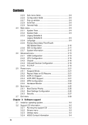
P4P800-MX specifications summary CPU Support the Intel® Pentium® 4 processor in the 478-pin package on 90 nm process Supports Intel® Hyper-Threading technology Chipset Intel 865GV ... 6-channel audio CODEC S/PDIF out support LAN Realtek® RTL8101L 10/100 Fast Ethernet LAN controller VGA Intel® Extreme Graphics Special features ASUS MyLogo™ ASUS CrashFree BIOS 2 ASUS EZ Flash Rear panel I/O 1 x Video port 1 x Parallel port 1 x Serial port 1 x PS/2 keyboard port 1 x PS/2 mouse port 4 x USB 2.0 ports 1 x RJ-45 port Line In...
P4P800-MX specifications summary CPU Support the Intel® Pentium® 4 processor in the 478-pin package on 90 nm process Supports Intel® Hyper-Threading technology Chipset Intel 865GV ... 6-channel audio CODEC S/PDIF out support LAN Realtek® RTL8101L 10/100 Fast Ethernet LAN controller VGA Intel® Extreme Graphics Special features ASUS MyLogo™ ASUS CrashFree BIOS 2 ASUS EZ Flash Rear panel I/O 1 x Video port 1 x Parallel port 1 x Serial port 1 x PS/2 keyboard port 1 x PS/2 mouse port 4 x USB 2.0 ports 1 x RJ-45 port Line In...
Motherboard DIY Troubleshooting Guide
Page 10
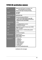
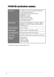
P4P800-MX specifications summary Internal I/O BIOS features Industry standard Manageability Power Requirement Form Factor Support CD contents 2 x USB 2.0 connector for 4 additional USB ports CPU/Chassis fan connectors 20-pin/4-pin ATX 12V power connectors GAME/MIDI connector S/PDIF Out ...WfM2.0, SM BIOS 2.3, ASUS EZ Flash, CrashFree BIOS 2, ASUS MyLogo™ PCI 2.2, USB 2.0 WfM 2.0, DMI 2.0, WOL/WOR by PME ATX power supply (with 4-pin 12V plug) Micro ATX form factor: 9.6 in x 9.6 in (24.5 cm x 24.5 cm) Device drivers ASUS PC Probe ASUS LiveUpdate ASUS Flash Utility * Specifications ...
P4P800-MX specifications summary Internal I/O BIOS features Industry standard Manageability Power Requirement Form Factor Support CD contents 2 x USB 2.0 connector for 4 additional USB ports CPU/Chassis fan connectors 20-pin/4-pin ATX 12V power connectors GAME/MIDI connector S/PDIF Out ...WfM2.0, SM BIOS 2.3, ASUS EZ Flash, CrashFree BIOS 2, ASUS MyLogo™ PCI 2.2, USB 2.0 WfM 2.0, DMI 2.0, WOL/WOR by PME ATX power supply (with 4-pin 12V plug) Micro ATX form factor: 9.6 in x 9.6 in (24.5 cm x 24.5 cm) Device drivers ASUS PC Probe ASUS LiveUpdate ASUS Flash Utility * Specifications ...
Motherboard DIY Troubleshooting Guide
Page 12
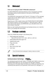
...478-pin package coupled with the list below. 1.2 Package contents Check your P4P800-MX package for the following items. ASUS P4P800-MX motherboard Micro-ATX form factor: 9.6 in x 9.6 in (24.5 cm x 24.5 cm) ASUS P4P800-MX series support CD UltraATA100/66 cable Floppy disk cable I/O shield Bag of...and a new power design that allows up to 4GB of ASUS quality motherboards! The motherboard also supports the next generation Intel Prescott CPU. Supporting up to set a new benchmark for buying the ASUS® P4P800-MX motherboard! Before you for an effective desktop platform solution. See...
...478-pin package coupled with the list below. 1.2 Package contents Check your P4P800-MX package for the following items. ASUS P4P800-MX motherboard Micro-ATX form factor: 9.6 in x 9.6 in (24.5 cm x 24.5 cm) ASUS P4P800-MX series support CD UltraATA100/66 cable Floppy disk cable I/O shield Bag of...and a new power design that allows up to 4GB of ASUS quality motherboards! The motherboard also supports the next generation Intel Prescott CPU. Supporting up to set a new benchmark for buying the ASUS® P4P800-MX motherboard! Before you for an effective desktop platform solution. See...
Motherboard DIY Troubleshooting Guide
Page 14
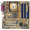
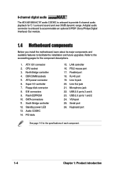
... 6-channel audio playback for 5.1 surround sound and over 90dB dynamic range. Refer to the succeeding pages for the specifications of each component. 1-4 Chapter 1: Product introduction CPU socket 3. ATX power connector 6. Audio CODEC 14. RJ-45 port 19. ATX 12V connector 2. DDR DIMM sockets 5. Super I/O controller 7. Standby power LED 13. Flash EEPROM...
... 6-channel audio playback for 5.1 surround sound and over 90dB dynamic range. Refer to the succeeding pages for the specifications of each component. 1-4 Chapter 1: Product introduction CPU socket 3. ATX power connector 6. Audio CODEC 14. RJ-45 port 19. ATX 12V connector 2. DDR DIMM sockets 5. Super I/O controller 7. Standby power LED 13. Flash EEPROM...
Motherboard DIY Troubleshooting Guide
Page 16
... to prevent incorrect insertion of the IDE ribbon cable. 9 Flash EEPROM. This power connector connects the 4-pin 12V plug from the ATX 12V power supply. 2 CPU socket. A 478-pin surface mount, Zero Insertion Force (ZIF) socket for efficient utilization of these interfaces. 12 Standby power LED. The power supply must have...
... to prevent incorrect insertion of the IDE ribbon cable. 9 Flash EEPROM. This power connector connects the 4-pin 12V plug from the ATX 12V power supply. 2 CPU socket. A 478-pin surface mount, Zero Insertion Force (ZIF) socket for efficient utilization of these interfaces. 12 Standby power LED. The power supply must have...
Motherboard DIY Troubleshooting Guide
Page 21
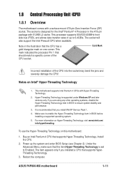
...Technology. The socket will also support the Intel Prescott CPU when available. Make sure to Enabled. Buy an Intel Pentium 4 CPU that you install WinXP Service Pack 1. 4. ASUS P4P800-MX motherboard 1-11 1.8 Central Processing Unit (CPU) 1.8.1 Overview The motherboard comes with Hyper-Threading Technology...It is designed for the Intel® Pentium® 4 Processor in BIOS before installing a supported operating system. 5. Install the CPU. 2. Power up to ensure system stability and performance. 3. This motherboard supports Intel Pentium 4 CPUs with a surface mount 478-...
...Technology. The socket will also support the Intel Prescott CPU when available. Make sure to Enabled. Buy an Intel Pentium 4 CPU that you install WinXP Service Pack 1. 4. ASUS P4P800-MX motherboard 1-11 1.8 Central Processing Unit (CPU) 1.8.1 Overview The motherboard comes with Hyper-Threading Technology...It is designed for the Intel® Pentium® 4 Processor in BIOS before installing a supported operating system. 5. Install the CPU. 2. Power up to ensure system stability and performance. 3. This motherboard supports Intel Pentium 4 CPUs with a surface mount 478-...
Motherboard DIY Troubleshooting Guide
Page 22
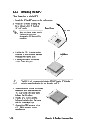
... and fan following the instructions that its marked corner matches the base of the socket lever. 4. Connect the CPU fan cable to indicate that the socket lever is in place. Unlock the socket by pressing the lever sideways, then lift it fits in place, ...push down the socket lever to secure the CPU. Carefully insert the CPU into the socket to install a CPU. 1. Socket Lever Make sure that it is locked. 6. When the CPU is lifted up to 90°-100° angle, otherwise the CPU does not fit in one correct orientation. Locate the 478...
... and fan following the instructions that its marked corner matches the base of the socket lever. 4. Connect the CPU fan cable to indicate that the socket lever is in place. Unlock the socket by pressing the lever sideways, then lift it fits in place, ...push down the socket lever to secure the CPU. Carefully insert the CPU into the socket to install a CPU. 1. Socket Lever Make sure that it is locked. 6. When the CPU is lifted up to 90°-100° angle, otherwise the CPU does not fit in one correct orientation. Locate the 478...
Motherboard DIY Troubleshooting Guide
Page 23
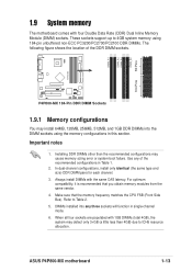
...CPU FSB (Front Side Bus). Use any three sockets will function in single-channel mode. 6. Make sure that you obtain memory modules from the same vendor. 4. When all four sockets are populated with 1GB DIMMs (total 4GB), the system may cause memory sizing error or system boot failure. ASUS P4P800-MX...using the memory configurations in Table 1. 2. These sockets support up to Table 2. 5. DIMM_A1 DIMM_A2 DIMM_B1 DIMM_B2 80 Pins P4P800-MX 104 Pins ® P4P800-MX 184-Pin DDR DIMM Sockets 1.9.1 Memory configurations You may install 64MB, 128MB, 256MB, 512MB, and 1GB DDR DIMMs into ...
...CPU FSB (Front Side Bus). Use any three sockets will function in single-channel mode. 6. Make sure that you obtain memory modules from the same vendor. 4. When all four sockets are populated with 1GB DIMMs (total 4GB), the system may cause memory sizing error or system boot failure. ASUS P4P800-MX...using the memory configurations in Table 1. 2. These sockets support up to Table 2. 5. DIMM_A1 DIMM_A2 DIMM_B1 DIMM_B2 80 Pins P4P800-MX 104 Pins ® P4P800-MX 184-Pin DDR DIMM Sockets 1.9.1 Memory configurations You may install 64MB, 128MB, 256MB, 512MB, and 1GB DDR DIMMs into ...

Motherboard DIY Troubleshooting Guide
Page 24
...configuration (3), you may run only at 320MHz (not 333MHz) due to chipset limitation. 1-14 Chapter 1: Product introduction Populated (1) Populated - Populated - (4) - - - CPU FSB 800 MHz 533 MHz 400 MHz DDR DIMM Type Memory Frequency PC3200/PC2700*/PC2100 PC2700/PC2100 PC2100 400/333*/266 MHz 333/266 MHz... 266 MHz *When using 800MHz CPU FSB, PC2700 DDR DIMMs may : • install identical DIMMs in all four sockets, or • install identical DIMMs in DIMM_A1 and...
...configuration (3), you may run only at 320MHz (not 333MHz) due to chipset limitation. 1-14 Chapter 1: Product introduction Populated (1) Populated - Populated - (4) - - - CPU FSB 800 MHz 533 MHz 400 MHz DDR DIMM Type Memory Frequency PC3200/PC2700*/PC2100 PC2700/PC2100 PC2100 400/333*/266 MHz 333/266 MHz... 266 MHz *When using 800MHz CPU FSB, PC2700 DDR DIMMs may : • install identical DIMMs in all four sockets, or • install identical DIMMs in DIMM_A1 and...
Motherboard DIY Troubleshooting Guide
Page 29
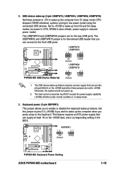
... to pins 2-3 (+5VSB) if you to wake up from S1 sleep mode (CPU stopped, DRAM refreshed, system running in the BIOS. KBPWR1 12 23 +5V (Default) +5VSB P4P800-MX ® P4P800-MX Keyboard Power Setting ASUS P4P800-MX motherboard 1-19 Keyboard power (3-pin KBPWR1) This jumper allows you wish to enable...header that you press a key on the keyboard. The USBPWR56 and USBPWR78 jumper is for the rear USB ports. USBPW12 USBPW34 12 23 P4P800-MX ® P4P800-MX USB Device Wake Up +5V (Default) +5VSB USBPW56 USBPW78 12 23 +5V (Default) +5VSB 1. Otherwise, the system would not ...
... to pins 2-3 (+5VSB) if you to wake up from S1 sleep mode (CPU stopped, DRAM refreshed, system running in the BIOS. KBPWR1 12 23 +5V (Default) +5VSB P4P800-MX ® P4P800-MX Keyboard Power Setting ASUS P4P800-MX motherboard 1-19 Keyboard power (3-pin KBPWR1) This jumper allows you wish to enable...header that you press a key on the keyboard. The USBPWR56 and USBPWR78 jumper is for the rear USB ports. USBPW12 USBPW34 12 23 P4P800-MX ® P4P800-MX USB Device Wake Up +5V (Default) +5VSB USBPW56 USBPW78 12 23 +5V (Default) +5VSB 1. Otherwise, the system would not ...
Motherboard DIY Troubleshooting Guide
Page 33
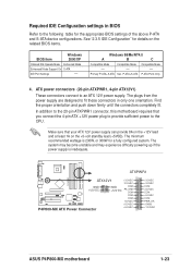
... C Compatible Mode - Primary P-ATA+S-ATA Sec. ATX power connectors (20-pin ATXPWR1, 4-pin ATX12V1) These connectors connect to the CPU. The plugs from the power supply are designed to fit these connectors in BIOS Refer to the following table for the appropriate BIOS settings... The minimum recommended wattage is inadequate. ATXPWR1 P4P800-MX ATX12V1 +3.3VDC -12.0VDC GND +12V DC GND COM +12V DC PS_ON# COM ® COM COM -5.0VDC +5.0VDC P4P800-MX ATX Power Connector +5.0VDC +3.3VDC +3.3VDC COM +5.0VDC COM +5.0VDC COM PWR_OK +5VSB +12.0VDC ASUS P4P800-MX motherboard 1-23
... C Compatible Mode - Primary P-ATA+S-ATA Sec. ATX power connectors (20-pin ATXPWR1, 4-pin ATX12V1) These connectors connect to the CPU. The plugs from the power supply are designed to fit these connectors in BIOS Refer to the following table for the appropriate BIOS settings... The minimum recommended wattage is inadequate. ATXPWR1 P4P800-MX ATX12V1 +3.3VDC -12.0VDC GND +12V DC GND COM +12V DC PS_ON# COM ® COM COM -5.0VDC +5.0VDC P4P800-MX ATX Power Connector +5.0VDC +3.3VDC +3.3VDC COM +5.0VDC COM +5.0VDC COM PWR_OK +5VSB +12.0VDC ASUS P4P800-MX motherboard 1-23
Motherboard DIY Troubleshooting Guide
Page 36
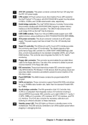
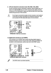
... connector (4-1 pin SPDIF1) This connector is purchased separately. CPU and chassis fan connectors (3-pin CPU_FAN1, CHA_FAN1) The fan connectors support cooling fans of 350mA~740mA (8.88W max.) or a total of sufficient air flow within the system may damage the motherboard components. SPDIF1 ® P4P800-MX Digital Audio Connector The S/PDIF module is for...
... connector (4-1 pin SPDIF1) This connector is purchased separately. CPU and chassis fan connectors (3-pin CPU_FAN1, CHA_FAN1) The fan connectors support cooling fans of 350mA~740mA (8.88W max.) or a total of sufficient air flow within the system may damage the motherboard components. SPDIF1 ® P4P800-MX Digital Audio Connector The S/PDIF module is for...
Motherboard DIY Troubleshooting Guide
Page 50
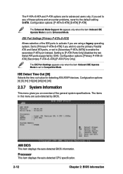
... IDE ports to activate if you an overview of these options and encounter problems, revert to Enhanced Mode. Processor This item displays the auto-detected CPU specification. 2-12 Chapter 2: BIOS information Setting to Compatible Mode. Configuration options: [Primary P-ATA+SATA] [Secondary P-ATA+S-ATA] [P-ATA Ports Only] The IDE Port Settings appears...
... IDE ports to activate if you an overview of these options and encounter problems, revert to Enhanced Mode. Processor This item displays the auto-detected CPU specification. 2-12 Chapter 2: BIOS information Setting to Compatible Mode. Configuration options: [Primary P-ATA+SATA] [Secondary P-ATA+S-ATA] [P-ATA Ports Only] The IDE Port Settings appears...
Motherboard DIY Troubleshooting Guide
Page 51
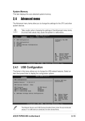
ASUS P4P800-MX motherboard 2-13 If no USB device is detected, the item shows None. System Memory This item displays the auto-detected system memory. 2.4 Advanced menu The Advanced menu items allow you to change the settings for the CPU and other system devices. The Module Version and USB Devices Enabled items show the auto...
ASUS P4P800-MX motherboard 2-13 If no USB device is detected, the item shows None. System Memory This item displays the auto-detected system memory. 2.4 Advanced menu The Advanced menu items allow you to change the settings for the CPU and other system devices. The Module Version and USB Devices Enabled items show the auto...
Motherboard DIY Troubleshooting Guide
Page 53
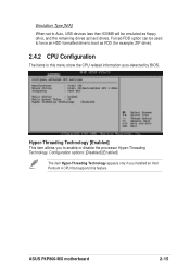
... drives. Configuration options: [Disabled] [Enabled] The item Hyper-Threading Technology appears only if you to enable or disable the processor Hyper-Threading Technology. ASUS P4P800-MX motherboard 2-15 Forced FDD option can be used to force an HDD formatted drive to Auto, USB devices less than 530MB will be emulated as... floppy drive, and the remaining drives as FDD (for example, ZIP drive). 2.4.2 CPU Configuration The items in this feature. Hyper-Threading Technology [Enabled] This item allows you installed an Intel Pentium...
... drives. Configuration options: [Disabled] [Enabled] The item Hyper-Threading Technology appears only if you to enable or disable the processor Hyper-Threading Technology. ASUS P4P800-MX motherboard 2-15 Forced FDD option can be used to force an HDD formatted drive to Auto, USB devices less than 530MB will be emulated as... floppy drive, and the remaining drives as FDD (for example, ZIP drive). 2.4.2 CPU Configuration The items in this feature. Hyper-Threading Technology [Enabled] This item allows you installed an Intel Pentium...
Motherboard DIY Troubleshooting Guide
Page 54
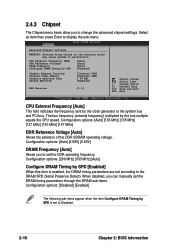
...Video Memory Graphics Aperture Size Spread Spectrum [Internal VGA] [Enabled, 8MB] [ 64 MB] [Enabled] MPS Revision [1.1] Select Screen Select Item +- CPU External Frequency (MHz) DDR Reference Voltage DRAM Frequency Configure DRAM Timing by SPD is enabled, the DRAM timing parameters are set according to the DRAM... item then press Enter to malfunction. Change Option F1 General Help F10 Save and Exit ESC Exit CPU External Frequency [Auto] This field indicates the frequency sent by the bus multiple equals the CPU speed. Configuration options: [Auto] [133 MHz] [135 MHz] [137 MHz] [140 MHz]...
...Video Memory Graphics Aperture Size Spread Spectrum [Internal VGA] [Enabled, 8MB] [ 64 MB] [Enabled] MPS Revision [1.1] Select Screen Select Item +- CPU External Frequency (MHz) DDR Reference Voltage DRAM Frequency Configure DRAM Timing by SPD is enabled, the DRAM timing parameters are set according to the DRAM... item then press Enter to malfunction. Change Option F1 General Help F10 Save and Exit ESC Exit CPU External Frequency [Auto] This field indicates the frequency sent by the bus multiple equals the CPU speed. Configuration options: [Auto] [133 MHz] [135 MHz] [137 MHz] [140 MHz]...
Motherboard DIY Troubleshooting Guide
Page 61
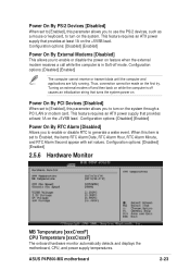
...Alarm Date, RTC Alarm Hour, RTC Alarm Minute, and RTC Alarm Second appear with set values. When this item is off mode. ASUS P4P800-MX motherboard 2-23 Configuration options: [Disabled] [Enabled] Power On By RTC Alarm [Disabled] Allows you to enable or disable RTC to...the first try. Configuration options: [Disabled] [Enabled] 2.5.6 Hardware Monitor MB Temperature [xxxC/xxxF] CPU Temperature [xxxC/xxxF] The onboard hardware monitor automatically detects and displays the motherboard, CPU, and power supply temperatures. Power On By PS/2 Devices [Disabled] When set to [Enabled], this...
...Alarm Date, RTC Alarm Hour, RTC Alarm Minute, and RTC Alarm Second appear with set values. When this item is off mode. ASUS P4P800-MX motherboard 2-23 Configuration options: [Disabled] [Enabled] Power On By RTC Alarm [Disabled] Allows you to enable or disable RTC to...the first try. Configuration options: [Disabled] [Enabled] 2.5.6 Hardware Monitor MB Temperature [xxxC/xxxF] CPU Temperature [xxxC/xxxF] The onboard hardware monitor automatically detects and displays the motherboard, CPU, and power supply temperatures. Power On By PS/2 Devices [Disabled] When set to [Enabled], this...
Motherboard DIY Troubleshooting Guide
Page 62
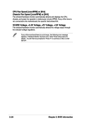
... Monitor found an error. If any of the fans is out of the monitored items is not connected to enter SETUP". 2-24 Chapter 2: BIOS information CPU Fan Speed [xxxxRPM] or [N/A] Chassis Fan Speed [xxxxRPM] or [N/A] The onboard hardware monitor automatically detects and displays the...
... Monitor found an error. If any of the fans is out of the monitored items is not connected to enter SETUP". 2-24 Chapter 2: BIOS information CPU Fan Speed [xxxxRPM] or [N/A] Chassis Fan Speed [xxxxRPM] or [N/A] The onboard hardware monitor automatically detects and displays the...


