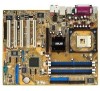
P4P800-E DELUXE Cpu - Asus
P4P800-E DELUXE Cpu
View Results Below
Free Asus P4P800-E DELUXE manuals!
Problems with Asus P4P800-E DELUXE?
Ask a Question
Free Asus P4P800-E DELUXE manuals!
Problems with Asus P4P800-E DELUXE?
Ask a Question
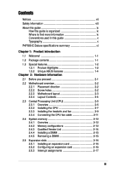
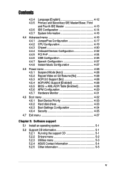
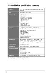
Related Manual Pages


Similar Questions

Cpu Fan Error
Press F1 To Start
cpu fan cleaned and heat seank is properly pested
cpu fan cleaned and heat seank is properly pested
(Posted by vikekartn 11 years ago)


Cpu Question
Does motherboard M5A78L le, supports amd flagship cpu fx-8350?
Does motherboard M5A78L le, supports amd flagship cpu fx-8350?
(Posted by tvkalendar 11 years ago)