
Motherboard DIY Troubleshooting Guide
Page 12
P4G8X-Serie Spezifikationsüberblick Rückwand E/A 1 x paralleler Anschluss 2 x serielle Anschlüsse 1 x PS/2-Tastaturanschluss 1 x PS/2-Mausanschluss 4 x USB 2.0-Anschlüsse 1 x RJ-45-...) S/PDIF In/Out-Anschluss (optional) CD/AUX/Modem Audio-Anschlüsse (optional) Front-Audioanschluss (optional) BIOS-Funktionen 4MB Flash ROM, Award BIOS, TCAV, PnP, DMI2.0, WfM2.0, SM BIOS2.3, CrashFree BIOS, Mehrsprachiges BIOS, ASUS EZ Flash, ASUS C.P.R., ASUS MyLogo2 Industriestandard PCI 2.2, USB 2.0 Verwaltung WfM 2.0. DMI 2.0, WOL/WOR über PME, Gehäuseeinbruch ...
P4G8X-Serie Spezifikationsüberblick Rückwand E/A 1 x paralleler Anschluss 2 x serielle Anschlüsse 1 x PS/2-Tastaturanschluss 1 x PS/2-Mausanschluss 4 x USB 2.0-Anschlüsse 1 x RJ-45-...) S/PDIF In/Out-Anschluss (optional) CD/AUX/Modem Audio-Anschlüsse (optional) Front-Audioanschluss (optional) BIOS-Funktionen 4MB Flash ROM, Award BIOS, TCAV, PnP, DMI2.0, WfM2.0, SM BIOS2.3, CrashFree BIOS, Mehrsprachiges BIOS, ASUS EZ Flash, ASUS C.P.R., ASUS MyLogo2 Industriestandard PCI 2.2, USB 2.0 Verwaltung WfM 2.0. DMI 2.0, WOL/WOR über PME, Gehäuseeinbruch ...

P4G8X User Manual
Page 4
... up 3.1 Starting up for the first time 3-1 3.2 Vocal POST Messages 3-2 3.3 Powering off the computer 3-4 Chapter 4: BIOS setup 4.1 Managing and updating your BIOS 4-1 4.1.1 Using ASUS EZ Flash to update the BIOS 4-1 4.1.2 Using AFLASH to update the BIOS 4-3 4.1.3 CrashFree BIOS feature 4-7 4.2 BIOS Setup program 4-8 4.2.1 BIOS menu bar 4-9 4.2.2 Legend bar 4-9 4.3 Main Menu 4-11 4.3.1 Primary and Secondary Master/Slave 4-13 4.3.2 Keyboard Features...
... up 3.1 Starting up for the first time 3-1 3.2 Vocal POST Messages 3-2 3.3 Powering off the computer 3-4 Chapter 4: BIOS setup 4.1 Managing and updating your BIOS 4-1 4.1.1 Using ASUS EZ Flash to update the BIOS 4-1 4.1.2 Using AFLASH to update the BIOS 4-3 4.1.3 CrashFree BIOS feature 4-7 4.2 BIOS Setup program 4-8 4.2.1 BIOS menu bar 4-9 4.2.2 Legend bar 4-9 4.3 Main Menu 4-11 4.3.1 Primary and Secondary Master/Slave 4-13 4.3.2 Keyboard Features...
P4G8X User Manual
Page 8
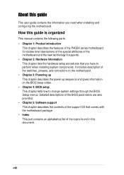
... the support CD that you need when installing and configuring the motherboard. Detailed descriptions of the BIOS parameters are also provided. • Chapter 5: Software support This chapter describes the contents of...this guide This user guide contains the information you have to change system settings through the BIOS Setup menus. viii How this guide is organized This manual contains the following parts: &#...the power up sequence and gives information on the BIOS beep codes. • Chapter 4: BIOS setup This chapter tells how to perform when installing system components. It includes ...
... the support CD that you need when installing and configuring the motherboard. Detailed descriptions of the BIOS parameters are also provided. • Chapter 5: Software support This chapter describes the contents of...this guide This user guide contains the information you have to change system settings through the BIOS Setup menus. viii How this guide is organized This manual contains the following parts: &#...the power up sequence and gives information on the BIOS beep codes. • Chapter 4: BIOS setup This chapter tells how to perform when installing system components. It includes ...

P4G8X User Manual
Page 11
... ASUS JumperFree™ mode ASUS POST Reporter™* ASUS EZ Plug™ ASUS MyLogo2 ASUS Q-Fan Technology ASUS EZ Flash USB 2.0 ready Power Loss Restart SFS (Stepless Frequency Selection) CPU throttle Adjustable CPU VCORE, memory, and AGP voltages Multi-language BIOS AGP warning LED (continued on P4G8X... memory Supports PC2100/PC1600 unbuffered ECC or non-ECC DDR DIMMs Expansion slots 1 x AGP Pro/8X (1.5V only) 5 x PCI (includes one ASUS BlueMagic PCI slot) IDE 2 x UltraDMA 100/66/33 connectors Serial ATA (optional) * Silicon Image Sil3112A controller 2 x Serial ATA connectors IEEE...
... ASUS JumperFree™ mode ASUS POST Reporter™* ASUS EZ Plug™ ASUS MyLogo2 ASUS Q-Fan Technology ASUS EZ Flash USB 2.0 ready Power Loss Restart SFS (Stepless Frequency Selection) CPU throttle Adjustable CPU VCORE, memory, and AGP voltages Multi-language BIOS AGP warning LED (continued on P4G8X... memory Supports PC2100/PC1600 unbuffered ECC or non-ECC DDR DIMMs Expansion slots 1 x AGP Pro/8X (1.5V only) 5 x PCI (includes one ASUS BlueMagic PCI slot) IDE 2 x UltraDMA 100/66/33 connectors Serial ATA (optional) * Silicon Image Sil3112A controller 2 x Serial ATA connectors IEEE...

P4G8X User Manual
Page 12
... in (30.5 cm x 24.5 cm) Device drivers ASUS PC Probe ASUS LiveUpdate Trend Micro™ PC-cillin 2002 anti-virus software Specifications are subject to change without notice. xii P4G8X series specifications summary Rear panel I/O Internal I/O BIOS features 1 x Parallel port 2 x Serial ports 1 x...connectors (optional) Front panel audio connector (optional) 4Mb Flash ROM, Award BIOS, TCAV, PnP, DMI2.0, WfM2.0, SM BIOS2.3, CrashFree BIOS, Multi-language BIOS, ASUS EZ Flash, ASUS C.P.R., ASUS MyLogo2 Industry standard Manageability Form Factor Support CD contents PCI 2.2, USB 2.0 WfM 2.0....
... in (30.5 cm x 24.5 cm) Device drivers ASUS PC Probe ASUS LiveUpdate Trend Micro™ PC-cillin 2002 anti-virus software Specifications are subject to change without notice. xii P4G8X series specifications summary Rear panel I/O Internal I/O BIOS features 1 x Parallel port 2 x Serial ports 1 x...connectors (optional) Front panel audio connector (optional) 4Mb Flash ROM, Award BIOS, TCAV, PnP, DMI2.0, WfM2.0, SM BIOS2.3, CrashFree BIOS, Multi-language BIOS, ASUS EZ Flash, ASUS C.P.R., ASUS MyLogo2 Industry standard Manageability Form Factor Support CD contents PCI 2.2, USB 2.0 WfM 2.0....

P4G8X User Manual
Page 17
...your existing power supply rather than buying a new ATX 12V power supply. This connector is onboard to provide 6-channel audio capability. See page 2-23. ASUS P4G8X series motherboard user guide 1-3 See page 2-27. See page 2-25. 6-channel digital audio (on audio models only) The RealTek ALC650, an 18... interfaces and the TI TSB43AB22 controller onboard provide high-speed and flexible PC connectivity to a wide range of the motherboard BIOS allows automatic re-setting to overclocking. The ALC650 supports independent variable sampling rates and built-in case the system hangs due to the...
...your existing power supply rather than buying a new ATX 12V power supply. This connector is onboard to provide 6-channel audio capability. See page 2-23. ASUS P4G8X series motherboard user guide 1-3 See page 2-27. See page 2-25. 6-channel digital audio (on audio models only) The RealTek ALC650, an 18... interfaces and the TI TSB43AB22 controller onboard provide high-speed and flexible PC connectivity to a wide range of the motherboard BIOS allows automatic re-setting to overclocking. The ALC650 supports independent variable sampling rates and built-in case the system hangs due to the...
P4G8X User Manual
Page 18
...can easily update the system BIOS even before loading the operating system. ASUS Multi-language BIOS The multi-language BIOS allows you to personalize and add style to select the language of boot errors, if any. CrashFree BIOS This feature allows you to restore the original BIOS data from a floppy disk... your choice from a floppy disk. This protection eliminates the need to customize the voice messages, and provides multi-language support. ASUS EZ Flash BIOS With the ASUS EZ Flash, you to use a DOS-based utility or boot from the available options. BlueMagic PCI slot The...
...can easily update the system BIOS even before loading the operating system. ASUS Multi-language BIOS The multi-language BIOS allows you to personalize and add style to select the language of boot errors, if any. CrashFree BIOS This feature allows you to restore the original BIOS data from a floppy disk... your choice from a floppy disk. This protection eliminates the need to customize the voice messages, and provides multi-language support. ASUS EZ Flash BIOS With the ASUS EZ Flash, you to use a DOS-based utility or boot from the available options. BlueMagic PCI slot The...
P4G8X User Manual
Page 19
...) provides more energy saving features for more than 4 seconds puts the system to sleep mode or to prevent overheating and damage. ASUS P4G8X series motherboard user guide 1-5 The system voltage levels are monitored to the memory and processor. Chassis intrusion detection The motherboard supports chassis...This feature allows multiple PCI transfers from PCI master buses to ensure stable supply of the BIOS setting. The system fan rotations per minute (RPM) is monitored by the ASUS ASIC to soft-off automatically when the system is ON, pressing the power switch for less...
...) provides more energy saving features for more than 4 seconds puts the system to sleep mode or to prevent overheating and damage. ASUS P4G8X series motherboard user guide 1-5 The system voltage levels are monitored to the memory and processor. Chassis intrusion detection The motherboard supports chassis...This feature allows multiple PCI transfers from PCI master buses to ensure stable supply of the BIOS setting. The system fan rotations per minute (RPM) is monitored by the ASUS ASIC to soft-off automatically when the system is ON, pressing the power switch for less...
P4G8X User Manual
Page 23
...15 Flash ROM. This Low Pin Count (LPC) interface provides the commonly used Super I /O controller. This 4Mb firmware contains the programmable BIOS program. 16 Standby power LED. The chipset supports a highperformance floppy disk controller for efficient utilization of these interfaces. 13 IEEE 1394 controller..../gain/mute functions for the motherboard, this LED is lit, there is a standby power on audio models only) 18 PCI slots. ASUS P4G8X series motherboard user guide 1-9 This LED lights up to allow 100Mbps, 200Mbps, and 400Mbps data transfers between the 1394 devices. (on the...
...15 Flash ROM. This Low Pin Count (LPC) interface provides the commonly used Super I /O controller. This 4Mb firmware contains the programmable BIOS program. 16 Standby power LED. The chipset supports a highperformance floppy disk controller for efficient utilization of these interfaces. 13 IEEE 1394 controller..../gain/mute functions for the motherboard, this LED is lit, there is a standby power on audio models only) 18 PCI slots. ASUS P4G8X series motherboard user guide 1-9 This LED lights up to allow 100Mbps, 200Mbps, and 400Mbps data transfers between the 1394 devices. (on the...

P4G8X User Manual
Page 31
...1. 4. It is supported under Windows XP and Linux 2.4.x (kernel) and later versions only. Make sure to compile the code. ASUS P4G8X series motherboard user guide 2-5 This mark indicates the processor Pin 1 that the CPU Gold Mark has a gold triangular mark on 0.13...on Intel® Hyper-Threading Technology 1. 2.4 Central Processing Unit (CPU) 2.4.1 Overview The motherboard comes with HyperThreading Technology. 2. Note in BIOS before installing a supported operating system. 5. Notes on Hyper-Threading Technology, visit www.intel.com/info/hyperthreading. Under Linux, use the Hyper-...
...1. 4. It is supported under Windows XP and Linux 2.4.x (kernel) and later versions only. Make sure to compile the code. ASUS P4G8X series motherboard user guide 2-5 This mark indicates the processor Pin 1 that the CPU Gold Mark has a gold triangular mark on 0.13...on Intel® Hyper-Threading Technology 1. 2.4 Central Processing Unit (CPU) 2.4.1 Overview The motherboard comes with HyperThreading Technology. 2. Note in BIOS before installing a supported operating system. 5. Notes on Hyper-Threading Technology, visit www.intel.com/info/hyperthreading. Under Linux, use the Hyper-...

P4G8X User Manual
Page 32
... CPU does not fit in completely. 2-6 Chapter 2: Hardware information Unlock the socket by pressing the lever sideways, then lift it up the system and enter BIOS Setup (see Chapter 4). Install the CPU. 2. The item appears only if you installed a CPU that supports Hyper-Threading Technology. Socket Lever 90 - 100 Make sure...
... CPU does not fit in completely. 2-6 Chapter 2: Hardware information Unlock the socket by pressing the lever sideways, then lift it up the system and enter BIOS Setup (see Chapter 4). Install the CPU. 2. The item appears only if you installed a CPU that supports Hyper-Threading Technology. Socket Lever 90 - 100 Make sure...
P4G8X User Manual
Page 40
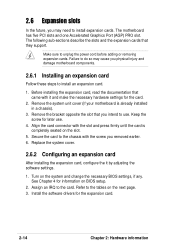
... hardware settings for information on the slot. 5. Refer to the tables on the system and change the necessary BIOS settings, if any. Remove the system unit cover (if your motherboard is completely seated on BIOS setup. 2. Secure the card to the chassis with it by adjusting the software settings. 1. Turn on the...
... hardware settings for information on the slot. 5. Refer to the tables on the system and change the necessary BIOS settings, if any. Remove the system unit cover (if your motherboard is completely seated on BIOS setup. 2. Secure the card to the chassis with it by adjusting the software settings. 1. Turn on the...

P4G8X User Manual
Page 44
You can automatically reset parameter settings to re-enter data. To erase the RTC RAM: 1. For system failure due to overclocking. 3. P4G8X ® P4G8X Clear RTC RAM CLRTC 2 1 Normal (Default) 3 2 Clear CMOS You do not need to clear the RTC when the system hangs due to overclocking, ... and turn ON the computer. 4. Shut down the key during the boot process and enter BIOS setup to default values. 2-18 Chapter 2: Hardware information Hold down and reboot the system so BIOS can clear the CMOS memory of date, time, and system setup parameters by the onboard button...
You can automatically reset parameter settings to re-enter data. To erase the RTC RAM: 1. For system failure due to overclocking. 3. P4G8X ® P4G8X Clear RTC RAM CLRTC 2 1 Normal (Default) 3 2 Clear CMOS You do not need to clear the RTC when the system hangs due to overclocking, ... and turn ON the computer. 4. Shut down the key during the boot process and enter BIOS setup to default values. 2-18 Chapter 2: Hardware information Hold down and reboot the system so BIOS can clear the CMOS memory of date, time, and system setup parameters by the onboard button...

P4G8X User Manual
Page 46
... by setting its jumper accordingly. IDE connectors (40-1 pin PRI_IDE, SEC_IDE) This connector supports the provided UltraDMA/100/66 IDE hard disk ribbon cable. P4G8X ® P4G8X IDE Connectors SEC_IDE PRI_IDE NOTE: Orient the red markings (usually zigzag) on the UltraDMA/100/66 cable is removed to the hard disk documentation for... you connect the cables. 2. This prevents incorrect orientation when you connect non-UltraDMA/100/66 devices to be both master devices with two ribbon cables - 3. BIOS supports specific device bootup.
... by setting its jumper accordingly. IDE connectors (40-1 pin PRI_IDE, SEC_IDE) This connector supports the provided UltraDMA/100/66 IDE hard disk ribbon cable. P4G8X ® P4G8X IDE Connectors SEC_IDE PRI_IDE NOTE: Orient the red markings (usually zigzag) on the UltraDMA/100/66 cable is removed to the hard disk documentation for... you connect the cables. 2. This prevents incorrect orientation when you connect non-UltraDMA/100/66 devices to be both master devices with two ribbon cables - 3. BIOS supports specific device bootup.

P4G8X User Manual
Page 47
...enter the SATARaid™ utility and SATA BIOS setup during POST if there are shorted with a jumper cap. By default, the pins labeled "Chassis Signal" and "Ground" are no connected Serial ATA devices. 5. P4G8X ® P4G8X SATA Connectors GND RSATA_RXP2 RSATA_RXN2 GND RSATA_TXN2 ... sends a high-level signal to this lead to record a chassis intrusion event. CHASSIS +5VSB_MB Chassis Signal GND P4G8X ® P4G8X Chassis Alarm Lead (Default) ASUS P4G8X series motherboard user guide 2-21 Serial ATA connectors (7-pin SATA1, SATA1) These next generation connectors support the thin Serial...
...enter the SATARaid™ utility and SATA BIOS setup during POST if there are shorted with a jumper cap. By default, the pins labeled "Chassis Signal" and "Ground" are no connected Serial ATA devices. 5. P4G8X ® P4G8X SATA Connectors GND RSATA_RXP2 RSATA_RXN2 GND RSATA_TXN2 ... sends a high-level signal to this lead to record a chassis intrusion event. CHASSIS +5VSB_MB Chassis Signal GND P4G8X ® P4G8X Chassis Alarm Lead (Default) ASUS P4G8X series motherboard user guide 2-21 Serial ATA connectors (7-pin SATA1, SATA1) These next generation connectors support the thin Serial...

P4G8X User Manual
Page 53
See section "4.4.2 I/O Device Configuration" for use with IR. IR_CON 1 Front View Back View +5V IRRX GND IRTX P4G8X ® P4G8X Infrared Module Connector IRTX GND IRRX +5V (NC) 15. This module mounts to the 1394 module. Doing so will damage the ...GND TPA1+ 1 IE1394_2 GND +12V +12V TPB0+ TPB1GND GND TPA0+ TPA1- ASUS P4G8X series motherboard user guide 2-27 P4G8X ® 1 IE1394_1 GND +12V TPB0GND TPA0- Use the five pins as shown in BIOS to set UART2 for details. P4G8X IEEE-1394 Connectors NEVER connect a USB cable to these connectors, and the 6-pin...
See section "4.4.2 I/O Device Configuration" for use with IR. IR_CON 1 Front View Back View +5V IRRX GND IRTX P4G8X ® P4G8X Infrared Module Connector IRTX GND IRRX +5V (NC) 15. This module mounts to the 1394 module. Doing so will damage the ...GND TPA1+ 1 IE1394_2 GND +12V +12V TPB0+ TPB1GND GND TPA0+ TPA1- ASUS P4G8X series motherboard user guide 2-27 P4G8X ® 1 IE1394_1 GND +12V TPB0GND TPA0- Use the five pins as shown in BIOS to set UART2 for details. P4G8X IEEE-1394 Connectors NEVER connect a USB cable to these connectors, and the 6-pin...

P4G8X User Manual
Page 55
... system into a suspend mode, or "green" mode, where system activity is in the ON mode for rebooting the system without turning off the system power. ASUS P4G8X series motherboard user guide 2-29 • System Power LED Lead (3-1 pin PLED) This 3-1 pin connector connects to this 2-pin connector. • ATX Power Switch / Soft... speaker and allows you to hear system beeps and warnings. • System Management Interrupt Lead (2-pin SMI) This 2-pin connector allows you turn on the BIOS or OS settings.
... system into a suspend mode, or "green" mode, where system activity is in the ON mode for rebooting the system without turning off the system power. ASUS P4G8X series motherboard user guide 2-29 • System Power LED Lead (3-1 pin PLED) This 3-1 pin connector connects to this 2-pin connector. • ATX Power Switch / Soft... speaker and allows you to hear system beeps and warnings. • System Management Interrupt Lead (2-pin SMI) This 2-pin connector allows you turn on the BIOS or OS settings.

P4G8X User Manual
Page 57
Powering up sequence and gives information on the BIOS beep codes. Chapter 3 This chapter describes the power up
Powering up sequence and gives information on the BIOS beep codes. Chapter 3 This chapter describes the power up

P4G8X User Manual
Page 59
...at a lower frequency You will hear the vocal POST messages instead. 7. At power on the chain) c. ASUS P4G8X series motherboard user guide 3-1 Turn on the screen. Monitor b. System running , the BIOS beeps or additional messages appear on the devices in Chapter 4. External SCSI devices (starting with "green" standards or... cover. 2. The system then runs the power-on the system front panel case lights up. You will not hear the BIOS beeps when the ASUS POST Reporter™ is working Meaning No error during POST No DRAM installed or detected Video card not found or video card...
...at a lower frequency You will hear the vocal POST messages instead. 7. At power on the chain) c. ASUS P4G8X series motherboard user guide 3-1 Turn on the screen. Monitor b. System running , the BIOS beeps or additional messages appear on the devices in Chapter 4. External SCSI devices (starting with "green" standards or... cover. 2. The system then runs the power-on the system front panel case lights up. You will not hear the BIOS beeps when the ASUS POST Reporter™ is working Meaning No error during POST No DRAM installed or detected Video card not found or video card...

P4G8X User Manual
Page 60
...; Install 184-pin unbuffered PC2100/1600 DIMMs into one of the default POST messages and their corresponding actions, if any. See the "ASUS contact information" on the DIMM sockets are not defective. • Refer to the recommended settings. Following is not defective. • ...Check your DIMMs are properly installed. • Make sure that your CPU settings in BIOS and make sure you only set to section "2.5 System memory" for assistance. See section "4.4 Advanced menu." 3-2 Chapter 3: Powering up This ...
...; Install 184-pin unbuffered PC2100/1600 DIMMs into one of the default POST messages and their corresponding actions, if any. See the "ASUS contact information" on the DIMM sockets are not defective. • Refer to the recommended settings. Following is not defective. • ...Check your DIMMs are properly installed. • Make sure that your CPU settings in BIOS and make sure you only set to section "2.5 System memory" for assistance. See section "4.4 Advanced menu." 3-2 Chapter 3: Powering up This ...


