P4BGV-MX User Manual
Page 3
... and updating your BIOS 2-2 2.1.1 Using ASUS EZ FLASH to update the BIOS 2-2 2.1.2 Using ASUS AFLASH to find more information vii ASUS contact information vii Specifications summary ix Chapter 1 - Motherboard Info 1-1 1.1 Welcome 1-2 1.2 Package contents 1-2 1.3 Introduction 1-3 1.4 Motherboard components 1-3 1.5 Motherboard layout 1-6 1.6 Before you proceed ... Safety information vi About this guide vii Conventions used in this guide vii Where to update the BIOS 2-4 Updating BIOS procedures 2-5 2.2 BIOS Setup Program 2-7 2.2.1 BIOS menu bar 2-7 2.2.2 Legend bar 2-8 iii
... and updating your BIOS 2-2 2.1.1 Using ASUS EZ FLASH to update the BIOS 2-2 2.1.2 Using ASUS AFLASH to find more information vii ASUS contact information vii Specifications summary ix Chapter 1 - Motherboard Info 1-1 1.1 Welcome 1-2 1.2 Package contents 1-2 1.3 Introduction 1-3 1.4 Motherboard components 1-3 1.5 Motherboard layout 1-6 1.6 Before you proceed ... Safety information vi About this guide vii Conventions used in this guide vii Where to update the BIOS 2-4 Updating BIOS procedures 2-5 2.2 BIOS Setup Program 2-7 2.2.1 BIOS menu bar 2-7 2.2.2 Legend bar 2-8 iii

P4BGV-MX User Manual
Page 9
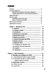
P4BGV-MX specifications summary CPU Chipset Front Side Bus (FSB) Memory Expansion slots IDE Audio LAN Special Features Back Panel I/O Ports Internal I/O Connectors Socket 478 ofr Intel ... PC2100/1600 non-ECC DDR SDRAM 3 x PCI 2 x UltraDMA 100/66 RealTek 2-channel CODEC RealTek 8101L PCI LAN integrated 10/100Mbps Fast Ethernet Power Loss Restart ASUS JumperFree BIOS write protections CPU Throttle 1 x Parallel 1 x Serial 1 x VGA 1 x PS/2 Keyboard 1 x PS/2 Mouse 4 x USB 2.0 1 x RJ-45 Port CPU/Chassis FAN connector 20 pin ATX power connector...
P4BGV-MX specifications summary CPU Chipset Front Side Bus (FSB) Memory Expansion slots IDE Audio LAN Special Features Back Panel I/O Ports Internal I/O Connectors Socket 478 ofr Intel ... PC2100/1600 non-ECC DDR SDRAM 3 x PCI 2 x UltraDMA 100/66 RealTek 2-channel CODEC RealTek 8101L PCI LAN integrated 10/100Mbps Fast Ethernet Power Loss Restart ASUS JumperFree BIOS write protections CPU Throttle 1 x Parallel 1 x Serial 1 x VGA 1 x PS/2 Keyboard 1 x PS/2 Mouse 4 x USB 2.0 1 x RJ-45 Port CPU/Chassis FAN connector 20 pin ATX power connector...
P4BGV-MX User Manual
Page 10
x P4BGV-MX specifications summary BIOS features 2Mb Flash ROM, EEPROM, ASUS JumperFree, Award BIOS with ACPI, DMI2.0, PnP, WfM2.0, Green, TCAV (Trend Chip Away Virus) Industry standard PCI 2.2, USB 2.0. Manageability WfM2.0, DMI2.0, WOR by PME, WOL by BME Form Factor Micro-ATX form factor: 8.6 in x 9.6 in Support CD contents Device drivers ASUS PC Probe Trend Microtm PC-cillin 2002 anti-virus software ASUS LiveUpdate Utility Accessories User's manual Support CD 1 x USB Bracket IDE cable FDD cable * Specifications are subject to change without notice.
x P4BGV-MX specifications summary BIOS features 2Mb Flash ROM, EEPROM, ASUS JumperFree, Award BIOS with ACPI, DMI2.0, PnP, WfM2.0, Green, TCAV (Trend Chip Away Virus) Industry standard PCI 2.2, USB 2.0. Manageability WfM2.0, DMI2.0, WOR by PME, WOL by BME Form Factor Micro-ATX form factor: 8.6 in x 9.6 in Support CD contents Device drivers ASUS PC Probe Trend Microtm PC-cillin 2002 anti-virus software ASUS LiveUpdate Utility Accessories User's manual Support CD 1 x USB Bracket IDE cable FDD cable * Specifications are subject to change without notice.

P4BGV-MX User Manual
Page 14
... the +5V standby lead (+5VSB). 6 Super I /O functionality. The chipset supports a high-performance floppy disk controller for two PCI Slots. 11 ASUS ASIC. Both the primary(blue) and secondary(black) connectors are slotted to prevent incorrect insertion of the floppy disk cable. 8 IDE Connectors. A...pin DIMM sockets support up to prevent incorrect insertion of the IDE ribbon cable. 9 Flash ROM. This 2Mb firmware contains the programmable BIOS program. 10 South bridge controller. This Intel ICH4 FW82801DB controller integrates the AC'97 Interface, six Universal Serial Bus 2.0, two IDE ...
... the +5V standby lead (+5VSB). 6 Super I /O functionality. The chipset supports a high-performance floppy disk controller for two PCI Slots. 11 ASUS ASIC. Both the primary(blue) and secondary(black) connectors are slotted to prevent incorrect insertion of the floppy disk cable. 8 IDE Connectors. A...pin DIMM sockets support up to prevent incorrect insertion of the IDE ribbon cable. 9 Flash ROM. This 2Mb firmware contains the programmable BIOS program. 10 South bridge controller. This Intel ICH4 FW82801DB controller integrates the AC'97 Interface, six Universal Serial Bus 2.0, two IDE ...

P4BGV-MX User Manual
Page 18
... See Chapter 2 for the expansion card. 1-8 Chapter 1: Motherboard Information Turn on BIOS setup. 2. Refer to the card. DO NOT force a DIMM into a socket to 2GB non-ECC PC2100/1600 DDR. 80 Pins P4BGV-MX 104 Pins P4BGV-MX 184-Pin DDR DIMM Sockets 1. A DDR DIMM is keyed with a notch so... that supports up to avoid damaging the DIMM. 1.9 Expansion slots The P4BGV-MX motherboard has three (3) expansion slots. The following sub-sections describe the slots and the expansion cards that they support. 1.9.1 Configuring an expansion...
... See Chapter 2 for the expansion card. 1-8 Chapter 1: Motherboard Information Turn on BIOS setup. 2. Refer to the card. DO NOT force a DIMM into a socket to 2GB non-ECC PC2100/1600 DDR. 80 Pins P4BGV-MX 104 Pins P4BGV-MX 184-Pin DDR DIMM Sockets 1. A DDR DIMM is keyed with a notch so... that supports up to avoid damaging the DIMM. 1.9 Expansion slots The P4BGV-MX motherboard has three (3) expansion slots. The following sub-sections describe the slots and the expansion cards that they support. 1.9.1 Configuring an expansion...
P4BGV-MX User Manual
Page 21
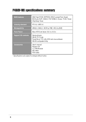
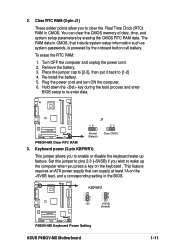
...and turn ON the computer. 6. J1 P4BGV-MX P4BGV-MX Clear RTC RAM 12 23 Normal (Default) Clear CMOS 3. P4BGV-MX KBPWR1 2 1 +5V 3 2 +5VSB (Default) P4BGV-MX Keyboard Power Setting ASUS P4BGV-MX Motherboard 1-11 2. Re-install the battery. 5. Hold down the key during the boot process and enter BIOS setup to [1-2] 4. Set this jumper ...the computer when you to clear the Real Time Clock (RTC) RAM in CMOS. Remove the battery. 3. The RAM data in the BIOS. Keyboard power (3-pin KBPWR1) This jumper allows you press a key on the +5VSB lead, and a corresponding setting in CMOS, ...
...and turn ON the computer. 6. J1 P4BGV-MX P4BGV-MX Clear RTC RAM 12 23 Normal (Default) Clear CMOS 3. P4BGV-MX KBPWR1 2 1 +5V 3 2 +5VSB (Default) P4BGV-MX Keyboard Power Setting ASUS P4BGV-MX Motherboard 1-11 2. Re-install the battery. 5. Hold down the key during the boot process and enter BIOS setup to [1-2] 4. Set this jumper ...the computer when you to clear the Real Time Clock (RTC) RAM in CMOS. Remove the battery. 3. The RAM data in the BIOS. Keyboard power (3-pin KBPWR1) This jumper allows you press a key on the +5VSB lead, and a corresponding setting in CMOS, ...

P4BGV-MX User Manual
Page 22
.... 1.11 Connectors This section describes and illustrates the connectors on the UltraDMA cable connector. P4BGV-MX P4BGV-MX IDE Connectors SEC_IDE PRI_IDE NOTE: Orient the red markings (usually zigzag) on each IDE connector is recommended that you connect the cables. BIOS supports specific device bootup. You may configure two hard disks to PIN 1. one for...
.... 1.11 Connectors This section describes and illustrates the connectors on the UltraDMA cable connector. P4BGV-MX P4BGV-MX IDE Connectors SEC_IDE PRI_IDE NOTE: Orient the red markings (usually zigzag) on each IDE connector is recommended that you connect the cables. BIOS supports specific device bootup. You may configure two hard disks to PIN 1. one for...
P4BGV-MX User Manual
Page 27
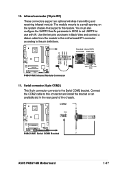
... (10-pin IR1) These connectors support an optional wireless transmitting and receiving infrared module. COM2 PIN 1 P4BGV-MX P4BGV-MX Serial COM2 Bracket ASUS P4BGV-MX Motherboard 1-17 Use the ten pins as shown in BIOS to the Serial COM2 bracket. P4BGV-MX IRAX GND CIRRX CIR+5V +5V IRRX GND IRTX Standard Infrared (SIR) Front View Back View SIR...
... (10-pin IR1) These connectors support an optional wireless transmitting and receiving infrared module. COM2 PIN 1 P4BGV-MX P4BGV-MX Serial COM2 Bracket ASUS P4BGV-MX Motherboard 1-17 Use the ten pins as shown in BIOS to the Serial COM2 bracket. P4BGV-MX IRAX GND CIRRX CIR+5V +5V IRRX GND IRTX Standard Infrared (SIR) Front View Back View SIR...

P4BGV-MX User Manual
Page 28
... 2-pin connector connects to the case-mounted speaker and allows you turn on the BIOS or OS settings. Keyboard Lock Speaker Power LED Connector +5 V PLED Keylock Ground +5V Ground Ground Speaker ExtSMI# Ground PWR Ground Reset Ground P4BGV-MX P4BGV-MX System Panel Connectors Reset SW SMI Lead ATX Power Switch* * Requires an ATX power...
... 2-pin connector connects to the case-mounted speaker and allows you turn on the BIOS or OS settings. Keyboard Lock Speaker Power LED Connector +5 V PLED Keylock Ground +5V Ground Ground Speaker ExtSMI# Ground PWR Ground Reset Ground P4BGV-MX P4BGV-MX System Panel Connectors Reset SW SMI Lead ATX Power Switch* * Requires an ATX power...
P4BGV-MX User Manual
Page 29
Chapter 2 This chapter gives information about the ASUS P4BGV-MX Binary Input/Output System (BIOS).This chapter includes updating the BIOS using the ASUS AFLASH BIOS that is bundled with the support CD. BIOS Information ASUS P4BGV-MX Motherboard 2-1
Chapter 2 This chapter gives information about the ASUS P4BGV-MX Binary Input/Output System (BIOS).This chapter includes updating the BIOS using the ASUS AFLASH BIOS that is bundled with the support CD. BIOS Information ASUS P4BGV-MX Motherboard 2-1
P4BGV-MX User Manual
Page 30
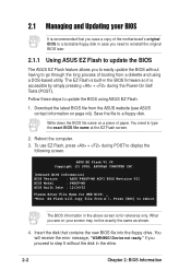
...Power-On Self Tests (POST). Insert the disk that you see ASUS contact information on a piece of booting from A:\, Press [ESC] to reboot The BIOS information in the BIOS firmware so it is for NEW BIOS: _ *Note: EZ Flash will receive the error message, "WARNING...screen may not be exactly the same as shown. 4. Reboot the computer. 3. ASUS EZ Flash V1.00 Copyright (C) 2002, ASUSTeK COMPUTER INC. [Onboard BIOS Information] BIOS Version : ASUS P4BGV-MX ACPI BIOS Revision 001 BIOS Model : P4BGV-MX BIOS Built Date : 12/16/02 Please Enter File Name for reference only. Device ...
...Power-On Self Tests (POST). Insert the disk that you see ASUS contact information on a piece of booting from A:\, Press [ESC] to reboot The BIOS information in the BIOS firmware so it is for NEW BIOS: _ *Note: EZ Flash will receive the error message, "WARNING...screen may not be exactly the same as shown. 4. Reboot the computer. 3. ASUS EZ Flash V1.00 Copyright (C) 2002, ASUSTeK COMPUTER INC. [Onboard BIOS Information] BIOS Version : ASUS P4BGV-MX ACPI BIOS Revision 001 BIOS Model : P4BGV-MX BIOS Built Date : 12/16/02 Please Enter File Name for reference only. Device ...

P4BGV-MX User Manual
Page 31
... Main BIOS area 2. EZ Flash will automatically access drive A to reboot the system with the update process. Press . 6. Flash Memory: SST 49LF004 1. Doing so may cause system boot failure. 8. When the update process is done, the message, "Press a key to completely update the main BIOS area and the boot block area. ASUS P4BGV-MX Motherboard...
... Main BIOS area 2. EZ Flash will automatically access drive A to reboot the system with the update process. Press . 6. Flash Memory: SST 49LF004 1. Doing so may cause system boot failure. 8. When the update process is done, the message, "Press a key to completely update the main BIOS area and the boot block area. ASUS P4BGV-MX Motherboard...

P4BGV-MX User Manual
Page 32
... programmable flash ROM on the upper left-hand corner of your motherboard, check the last four numbers of your screen during bootup. To determine the BIOS version of the code displayed on the motherboard. In DOS mode, type A:\AFLASH to create a bootable system disk. If the word "unknown" appears .... This file works only in DOS mode. Reboot the computer from the hard drive. AFLASH works only in DOS mode. Larger numbers represent a newer BIOS file. 1. It is your screen may be exactly the same as the first item in the boot sequence. 4. DO NOT copy AUTOEXEC.BAT and ...
... programmable flash ROM on the upper left-hand corner of your motherboard, check the last four numbers of your screen during bootup. To determine the BIOS version of the code displayed on the motherboard. In DOS mode, type A:\AFLASH to create a bootable system disk. If the word "unknown" appears .... This file works only in DOS mode. Reboot the computer from the hard drive. AFLASH works only in DOS mode. Larger numbers represent a newer BIOS file. 1. It is your screen may be exactly the same as the first item in the boot sequence. 4. DO NOT copy AUTOEXEC.BAT and ...
P4BGV-MX User Manual
Page 33
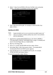
... Boot Block and ESCD screen appears. 5. To cancel this operation, press . ASUS P4BGV-MX Motherboard 2-5 At the Main Menu, type 2 then press . 5. The Save Current BIOS To File screen appears. 6. Download an updated ASUS BIOS file from the Internet (WWW or FTP) (see ASUS CONTACT INFORMATION on page x for details) and save to File from the floppy...
... Boot Block and ESCD screen appears. 5. To cancel this operation, press . ASUS P4BGV-MX Motherboard 2-5 At the Main Menu, type 2 then press . 5. The Save Current BIOS To File screen appears. 6. Download an updated ASUS BIOS file from the Internet (WWW or FTP) (see ASUS CONTACT INFORMATION on page x for details) and save to File from the floppy...

P4BGV-MX User Manual
Page 34
... programming is updated automatically only when necessary. The utility starts to successfully update a complete BIOS file, call the ASUS service center for support. 2-6 Chapter 2: BIOS Information Follow the onscreen instructions to start the update. 7. When prompted to confirm the BIOS update, press Y to continue. The boot block is done, the message "Flashed Successfully" appears...
... programming is updated automatically only when necessary. The utility starts to successfully update a complete BIOS file, call the ASUS service center for support. 2-6 Chapter 2: BIOS Information Follow the onscreen instructions to start the update. 7. When prompted to confirm the BIOS update, press Y to continue. The boot block is done, the message "Flashed Successfully" appears...
P4BGV-MX User Manual
Page 35
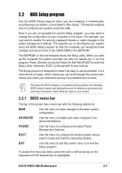
... requires you to change the configuration of your computer in the CMOS RAM of the screen has a menu bar with the following BIOS setup screens and descriptions are for reference purposes only, and may want to reconfigure your system using this program. The Setup program ... is a menu-driven program, which means you can recognize these changes and record them in the future. ASUS P4BGV-MX Motherboard 2-7 2.2 BIOS Setup program Use the BIOS Setup program when you are installing a motherboard, reconfiguring your system, or prompted to enter the Setup utility, otherwise, POST continues...
... requires you to change the configuration of your computer in the CMOS RAM of the screen has a menu bar with the following BIOS setup screens and descriptions are for reference purposes only, and may want to reconfigure your system using this program. The Setup program ... is a menu-driven program, which means you can recognize these changes and record them in the future. ASUS P4BGV-MX Motherboard 2-7 2.2 BIOS Setup program Use the BIOS Setup program when you are installing a motherboard, reconfiguring your system, or prompted to enter the Setup utility, otherwise, POST continues...

P4BGV-MX User Manual
Page 36
...corresponding functions. When a scroll bar appears to the right of the Setup screen is more information to the Item Specific Help window, the BIOS setup program also provides a General Help screen. Press to display the first page, press to go to navigate through the entire help document....to the main menu from any menu by simply pressing or the + combination. To exit the help window, press or . 2-8 Chapter 2: BIOS Information Navigation Key(s) Function Description or Displays the General Help screen from anywhere in the legend bar allow you to the last page. Saving ...
...corresponding functions. When a scroll bar appears to the right of the Setup screen is more information to the Item Specific Help window, the BIOS setup program also provides a General Help screen. Press to display the first page, press to go to navigate through the entire help document....to the main menu from any menu by simply pressing or the + combination. To exit the help window, press or . 2-8 Chapter 2: BIOS Information Navigation Key(s) Function Description or Displays the General Help screen from anywhere in the legend bar allow you to the last page. Saving ...
P4BGV-MX User Manual
Page 38
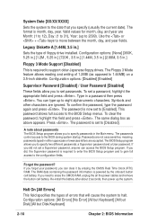
...alphanumeric characters. The RAM data containing the password information is now set a password, highlight the appropriate field and press . You can access the BIOS Setup program. The same dialog box as opposed to 1.44MB) on a 3.5-inch diskette. If you to set to [Disabled]. Configuration options: ...[All Errors] [No Error] [All but Keyboard] [All but Disk] [All but Disk/Keyboard] 2-10 Chapter 2: BIOS Information Symbols and other characters are Month: (1 to 12), Day: (1 to 31), Year: (up the system. The password is powered by erasing the...
...alphanumeric characters. The RAM data containing the password information is now set a password, highlight the appropriate field and press . You can access the BIOS Setup program. The same dialog box as opposed to 1.44MB) on a 3.5-inch diskette. If you to set to [Disabled]. Configuration options: ...[All Errors] [No Error] [All but Keyboard] [All but Disk] [All but Disk/Keyboard] 2-10 Chapter 2: BIOS Information Symbols and other characters are Month: (1 to 12), Day: (1 to 31), Year: (up the system. The password is powered by erasing the...
P4BGV-MX User Manual
Page 40
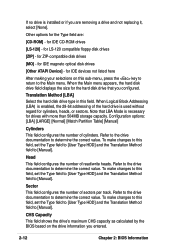
... Type HDD] and the Translation Method field to [Manual]. CHS Capacity This field shows the drive's maximum CHS capacity as calculated by the BIOS based on this field. Other options for LS-120 compatible floppy disk drives [ZIP] - Note that you configured. for IDE magneto optical...cylinders. Refer to the drive documentation to determine the correct value. If no drive is installed or if you entered. 2-12 Chapter 2: BIOS Information Sector This field configures the number of read/write heads. for ZIP-compatible disk drives [MO] - Head This field configures the ...
... Type HDD] and the Translation Method field to [Manual]. CHS Capacity This field shows the drive's maximum CHS capacity as calculated by the BIOS based on this field. Other options for LS-120 compatible floppy disk drives [ZIP] - Note that you configured. for IDE magneto optical...cylinders. Refer to the drive documentation to determine the correct value. If no drive is installed or if you entered. 2-12 Chapter 2: BIOS Information Sector This field configures the number of read/write heads. for ZIP-compatible disk drives [MO] - Head This field configures the ...
P4BGV-MX User Manual
Page 41
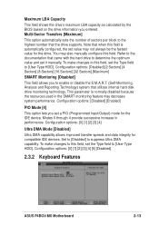
... through 4 provide successive increase in the SMART monitoring feature may decrease system performance. Configuration options: [0] [1] [2] [3] [4] [5] [Disabled] 2.3.2 Keyboard Features ASUS P4BGV-MX Motherboard 2-13 Note that came with the hard drive to [User Type HDD]. Configuration options: [0] [1] [2] [3] [4] Ultra DMA Mode [Disabled] Ultra DMA... disk drive monitoring technology. Maximum LBA Capacity This field shows the drive's maximum LBA capacity as calculated by the BIOS based on the drive information you set a PIO (Programmed Input/Output) mode for the IDE device. Refer to...
... through 4 provide successive increase in the SMART monitoring feature may decrease system performance. Configuration options: [0] [1] [2] [3] [4] [5] [Disabled] 2.3.2 Keyboard Features ASUS P4BGV-MX Motherboard 2-13 Note that came with the hard drive to [User Type HDD]. Configuration options: [0] [1] [2] [3] [4] Ultra DMA Mode [Disabled] Ultra DMA... disk drive monitoring technology. Maximum LBA Capacity This field shows the drive's maximum LBA capacity as calculated by the BIOS based on the drive information you set a PIO (Programmed Input/Output) mode for the IDE device. Refer to...


