
Motherboard DIY Troubleshooting Guide
Page 4
... 2-18 2.8 Connectors 2-22 Chapter 3: Powering up 3-1 3.1 Starting up for the first time 3-1 3.3 Powering off the computer 3-2 Chapter 4: BIOS setup 4-1 4.1 Managing and updating your BIOS 4-1 4.1.1 Using the computer system for the first time 4-1 4.1.2 Updating BIOS procedures 4-3 4.2 BIOS Setup program 4-5 4.2.1 BIOS menu bar 4-6 4.2.2 Legend bar 4-6 4.3 Main Menu 4-8 4.3.1 Primary and Secondary Master/Slave 4-9 4.3.2 Keyboard Features 4-13 4.4 Advanced Menu...
... 2-18 2.8 Connectors 2-22 Chapter 3: Powering up 3-1 3.1 Starting up for the first time 3-1 3.3 Powering off the computer 3-2 Chapter 4: BIOS setup 4-1 4.1 Managing and updating your BIOS 4-1 4.1.1 Using the computer system for the first time 4-1 4.1.2 Updating BIOS procedures 4-3 4.2 BIOS Setup program 4-5 4.2.1 BIOS menu bar 4-6 4.2.2 Legend bar 4-6 4.3 Main Menu 4-8 4.3.1 Primary and Secondary Master/Slave 4-9 4.3.2 Keyboard Features 4-13 4.4 Advanced Menu...

Motherboard DIY Troubleshooting Guide
Page 8
... installing system components. Detailed descriptions of the BIOS parameters are also provided. • Chapter 5: Software support This chapter describes the contents of the support CD that comes with the motherboard package. • Glossary This part lists the technical terms that you need when installing the ASUS P4B-M motherboard. How this guide is organized...
... installing system components. Detailed descriptions of the BIOS parameters are also provided. • Chapter 5: Software support This chapter describes the contents of the support CD that comes with the motherboard package. • Glossary This part lists the technical terms that you need when installing the ASUS P4B-M motherboard. How this guide is organized...
Motherboard DIY Troubleshooting Guide
Page 15
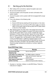
...two standard compatible UARTs, a Standard Infrared (SIR), one of the two major components of the IDE ribbon cable. 7 Floppy disk connector. ASUS P4B-M motherboard user guide 1-3 The MCH along with 400MHz system bus. 2 North bridge controller. The MCH provides the processor interface, system memory ...and a Flash ROM interface. 6 IDE connectors. One side of the floppy disk cable. 8 Flash EEPROM. This 2Mb firmware contains the programmable BIOS program. 9 DIP switches. This socket accommodates the Intel® Pentium® 4 478/Northwood Processor with the south bridge Intel I /O chipset...
...two standard compatible UARTs, a Standard Infrared (SIR), one of the two major components of the IDE ribbon cable. 7 Floppy disk connector. ASUS P4B-M motherboard user guide 1-3 The MCH along with 400MHz system bus. 2 North bridge controller. The MCH provides the processor interface, system memory ...and a Flash ROM interface. 6 IDE connectors. One side of the floppy disk cable. 8 Flash EEPROM. This 2Mb firmware contains the programmable BIOS program. 9 DIP switches. This socket accommodates the Intel® Pentium® 4 478/Northwood Processor with the south bridge Intel I /O chipset...

Motherboard DIY Troubleshooting Guide
Page 34
...- Onboard Audio - - - - - shared - - - Refer to the card. IRQ assignments for the expansion card. When using PCI cards on the system and change the necessary BIOS settings, if any. Install the software drivers for this motherboard A B C D E F G H PCI slot 1 - - - - - shared - - Onboard LAN - -... Data Processor 14* 9 Primary IDE Channel 15* 10 Secondary IDE Channel *These IRQs are usually available for information on BIOS setup. 2. Assign an IRQ to the tables below. 3. 2.6.2 Configuring an expansion card After physically installing the expansion card...
...- Onboard Audio - - - - - shared - - - Refer to the card. IRQ assignments for the expansion card. When using PCI cards on the system and change the necessary BIOS settings, if any. Install the software drivers for this motherboard A B C D E F G H PCI slot 1 - - - - - shared - - Onboard LAN - -... Data Processor 14* 9 Primary IDE Channel 15* 10 Secondary IDE Channel *These IRQs are usually available for information on BIOS setup. 2. Assign an IRQ to the tables below. 3. 2.6.2 Configuring an expansion card After physically installing the expansion card...

Motherboard DIY Troubleshooting Guide
Page 39
... active regardless of the settings of these jumpers allow you to pins 1-2 by default. P4B-M KBPWR 2 1 +5V (Default) 3 2 +5VSB ® P4B-M Keyboard Power Setting Figure 2-25 Keyboard Power Settings ASUS P4B-M motherboard user guide 2-19 2. The default is setting is the Space Bar). Setting ...P4B-M ® P4B-M USB/CNR Selection 12 Use External USB Ports (Default) Figure 2-24 USB Port Selection 23 Use CNR USB 3. Both jumpers are set to pins 1-2 (+5VSB) if you press a key on the keyboard (the default is on the +5VSB lead, and a corresponding setting in the BIOS...
... active regardless of the settings of these jumpers allow you to pins 1-2 by default. P4B-M KBPWR 2 1 +5V (Default) 3 2 +5VSB ® P4B-M Keyboard Power Setting Figure 2-25 Keyboard Power Settings ASUS P4B-M motherboard user guide 2-19 2. The default is setting is the Space Bar). Setting ...P4B-M ® P4B-M USB/CNR Selection 12 Use External USB Ports (Default) Figure 2-24 USB Port Selection 23 Use CNR USB 3. Both jumpers are set to pins 1-2 (+5VSB) if you press a key on the keyboard (the default is on the +5VSB lead, and a corresponding setting in the BIOS...

Motherboard DIY Troubleshooting Guide
Page 41
... the power cord and turn ON the computer. 6. To erase the RTC RAM: 1. Hold down the key during the boot process and enter BIOS setup to clear CMOS ASUS P4B-M motherboard user guide 2-21 Turn OFF the computer and unplug the power cord. 2. You can clear the CMOS memory of date, time, and...
... the power cord and turn ON the computer. 6. To erase the RTC RAM: 1. Hold down the key during the boot process and enter BIOS setup to clear CMOS ASUS P4B-M motherboard user guide 2-21 Turn OFF the computer and unplug the power cord. 2. You can clear the CMOS memory of date, time, and...

Motherboard DIY Troubleshooting Guide
Page 43
...as a slave device by setting its jumper accordingly. You may configure two hard disks to the UltraDMA/100/66 master device. ASUS P4B-M motherboard user guide 2-23 Primary/Secondary IDE connectors (40-1 pin IDE1/IDE2) This connector supports the provided UltraDMA/100/66 .../66 devices to the hard disk documentation for the secondary IDE connector. 1. BIOS supports specific device bootup. Refer to the secondary IDE connector. Secondary IDE Connector Primary IDE Connector P4B-M ® P4B-M IDE Connectors Figure 2-30 IDE Connectors NOTE: Orient the red markings (usually...
...as a slave device by setting its jumper accordingly. You may configure two hard disks to the UltraDMA/100/66 master device. ASUS P4B-M motherboard user guide 2-23 Primary/Secondary IDE connectors (40-1 pin IDE1/IDE2) This connector supports the provided UltraDMA/100/66 .../66 devices to the hard disk documentation for the secondary IDE connector. 1. BIOS supports specific device bootup. Refer to the secondary IDE connector. Secondary IDE Connector Primary IDE Connector P4B-M ® P4B-M IDE Connectors Figure 2-30 IDE Connectors NOTE: Orient the red markings (usually...

Motherboard DIY Troubleshooting Guide
Page 45
... Module Connector Figure 2-34 Infrared Module Connector Standard Infrared (SIR) Front View Back View IRTX +5V GND (NC) IRRX ASUS P4B-M motherboard user guide 2-25 USB header (10-1 pin USB23) If the USB port connectors on system chassis that support this feature. Use the five pins ...as shown in Back View and connect a ribbon cable from the module to the motherboard SIR connector according to an open slot in BIOS to a small opening on the rear panel are inadequate, a USB header is available for two additional USB port connectors. Infrared module connector (two 5-1 pin ...
... Module Connector Figure 2-34 Infrared Module Connector Standard Infrared (SIR) Front View Back View IRTX +5V GND (NC) IRRX ASUS P4B-M motherboard user guide 2-25 USB header (10-1 pin USB23) If the USB port connectors on system chassis that support this feature. Use the five pins ...as shown in Back View and connect a ribbon cable from the module to the motherboard SIR connector according to an open slot in BIOS to a small opening on the rear panel are inadequate, a USB header is available for two additional USB port connectors. Infrared module connector (two 5-1 pin ...
Motherboard DIY Troubleshooting Guide
Page 51
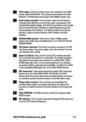
... beeps and warnings. • System Message LED Lead (2-pin MSG.LED) This 2-pin connector is for the system message LED that controls the system power. ASUS P4B-M motherboard user guide 2-31 The LED blinks when data is no incoming data signal. Pressing the power switch while in the ON mode for more... is ON, when there is received. Pressing the power switch turns the system between ON and SLEEP, or ON and SOFT OFF, depending on the BIOS or OS settings.
... beeps and warnings. • System Message LED Lead (2-pin MSG.LED) This 2-pin connector is for the system message LED that controls the system power. ASUS P4B-M motherboard user guide 2-31 The LED blinks when data is no incoming data signal. Pressing the power switch while in the ON mode for more... is ON, when there is received. Pressing the power switch turns the system between ON and SLEEP, or ON and SOFT OFF, depending on the BIOS or OS settings.

Motherboard DIY Troubleshooting Guide
Page 53
Powering up sequence and gives information on the BIOS beep codes. Chapter 3 This chapter describes the power up
Powering up sequence and gives information on the BIOS beep codes. Chapter 3 This chapter describes the power up
Motherboard DIY Troubleshooting Guide
Page 55
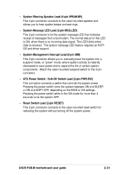
...Meaning No error during POST No DRAM installed or detected Video card not found or video card memory bad CPU overheated; System running , the BIOS beeps or additional messages appear on the front of the system chassis. 4. Follow the instructions in an endless loop One long beep followed ...for the first time 1. If you do not see anything within 30 seconds from the time you press the ATX power switch. ASUS P4B-M motherboard user guide 3-1 Award BIOS Beep Codes Beep One short beep when displaying logo Long beeps in Chapter 4. At power on the system front panel case lights...
...Meaning No error during POST No DRAM installed or detected Video card not found or video card memory bad CPU overheated; System running , the BIOS beeps or additional messages appear on the front of the system chassis. 4. Follow the instructions in an endless loop One long beep followed ...for the first time 1. If you do not see anything within 30 seconds from the time you press the ATX power switch. ASUS P4B-M motherboard user guide 3-1 Award BIOS Beep Codes Beep One short beep when displaying logo Long beeps in Chapter 4. At power on the system front panel case lights...

Motherboard DIY Troubleshooting Guide
Page 57
Detailed descriptions of the BIOS parameters are also provided. Chapter 4 This chapter tells how to change system settings through the BIOS Setup menus. BIOS setup
Detailed descriptions of the BIOS parameters are also provided. Chapter 4 This chapter tells how to change system settings through the BIOS Setup menus. BIOS setup
Motherboard DIY Troubleshooting Guide
Page 59
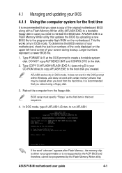
...is either not programmable or is not supported by the ACPI BIOS and therefore, cannot be loaded when you boot from the floppy disk. This file works only in the DOS prompt within Windows, and does not work in DOS mode. ASUS P4B-M motherboard user guide 4-1 Type COPY D:\AFLASH\AFLASH.EXE A:\... (assuming D is your CD-ROM drive) to copy AFLASH.EXE to the disk. 2. BIOS setup must specify "Floppy" as the first item in DOS mode. Larger ...
...is either not programmable or is not supported by the ACPI BIOS and therefore, cannot be loaded when you boot from the floppy disk. This file works only in the DOS prompt within Windows, and does not work in DOS mode. ASUS P4B-M motherboard user guide 4-1 Type COPY D:\AFLASH\AFLASH.EXE A:\... (assuming D is your CD-ROM drive) to copy AFLASH.EXE to the disk. 2. BIOS setup must specify "Floppy" as the first item in DOS mode. Larger ...

Motherboard DIY Troubleshooting Guide
Page 60
Save Current BIOS to File from the Main menu and press . The Save Current BIOS To File screen appears. 6. 5. Type a filename and the path, for example, A:\XXX-XX.XXX, then press . 4-2 Chapter 4: BIOS Setup Select 1.
Save Current BIOS to File from the Main menu and press . The Save Current BIOS To File screen appears. 6. 5. Type a filename and the path, for example, A:\XXX-XX.XXX, then press . 4-2 Chapter 4: BIOS Setup Select 1.

Motherboard DIY Troubleshooting Guide
Page 61
...the motherboard! 1. Boot from the Internet (WWW or FTP) (see ASUS CONTACT INFORMATION on page x for details) and save to the boot floppy disk you are sure that the new BIOS revision will solve your new BIOS and the path, for example, A:\XXX-XX.XXX, then press .... type AFLASH and then press . 4. At the Main Menu, type 2 then press . The Update BIOS Including Boot Block and ESCD screen appears. 5. Download an updated ASUS BIOS file from the floppy disk. 3. ASUS P4B-M motherboard user guide 4-3 Type the filename of your problems. Careless updating may result to start the update....
...the motherboard! 1. Boot from the Internet (WWW or FTP) (see ASUS CONTACT INFORMATION on page x for details) and save to the boot floppy disk you are sure that the new BIOS revision will solve your new BIOS and the path, for example, A:\XXX-XX.XXX, then press .... type AFLASH and then press . 4. At the Main Menu, type 2 then press . The Update BIOS Including Boot Block and ESCD screen appears. 5. Download an updated ASUS BIOS file from the floppy disk. 3. ASUS P4B-M motherboard user guide 4-3 Type the filename of your problems. Careless updating may result to start the update....
Motherboard DIY Troubleshooting Guide
Page 62
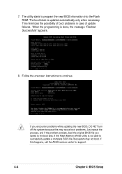
...process, and if the problem persists, load the original BIOS file you encounter problems while updating the new BIOS, DO NOT turn off the system because this happens, call the ASUS service center for support. 4-4 Chapter 4: BIOS Setup The utility starts to continue. Follow the onscreen ...instructions to program the new BIOS information into the Flash ROM. The boot block is done, the message "Flashed Successfully"...
...process, and if the problem persists, load the original BIOS file you encounter problems while updating the new BIOS, DO NOT turn off the system because this happens, call the ASUS service center for support. 4-4 Chapter 4: BIOS Setup The utility starts to continue. Follow the onscreen ...instructions to program the new BIOS information into the Flash ROM. The boot block is done, the message "Flashed Successfully"...

Motherboard DIY Troubleshooting Guide
Page 63
4.2 BIOS Setup... computer in the CMOS RAM of your BIOS." The Setup program is designed to make your system using the BIOS Setup program so that you wish to ...settings. It is constantly being updated, the following BIOS setup screens and descriptions are for reference purposes only... , or by turning the system off and then back on your screen. Because the BIOS software is a menu-driven program, which means you see on . Press during the Power... make it as possible. The EEPROM on the system chassis. Use the BIOS Setup program when you are not prompted to use as easy to enter ...
4.2 BIOS Setup... computer in the CMOS RAM of your BIOS." The Setup program is designed to make your system using the BIOS Setup program so that you wish to ...settings. It is constantly being updated, the following BIOS setup screens and descriptions are for reference purposes only... , or by turning the system off and then back on your screen. Because the BIOS software is a menu-driven program, which means you see on . Press during the Power... make it as possible. The EEPROM on the system chassis. Use the BIOS Setup program when you are not prompted to use as easy to enter ...

Motherboard DIY Troubleshooting Guide
Page 64
Navigation Key(s) Function Description or Displays the General Help screen from anywhere in the BIOS Setup Jumps to the Exit menu or returns to the main menu from a sub-menu Left or Right arrow Selects the menu item to the ... the first field or Moves the cursor to the last field Resets the current screen to its Setup Defaults Saves changes and exits Setup 4-6 Chapter 4: BIOS Setup EXIT Use this menu to enable and make changes to the basic system configuration. ADVANCED Use this menu to exit the current menu or...
Navigation Key(s) Function Description or Displays the General Help screen from anywhere in the BIOS Setup Jumps to the Exit menu or returns to the main menu from a sub-menu Left or Right arrow Selects the menu item to the ... the first field or Moves the cursor to the last field Resets the current screen to its Setup Defaults Saves changes and exits Setup 4-6 Chapter 4: BIOS Setup EXIT Use this menu to enable and make changes to the basic system configuration. ADVANCED Use this menu to exit the current menu or...

Motherboard DIY Troubleshooting Guide
Page 65
... keys to enter values and move the highlight to the right of each menu. Take some time to the Item Specific Help window, the BIOS setup program also provides a General Help screen. Use the key to return to the last page. Practice navigating through the entire help In... within a sub-menu as shown on saving changes and exiting the setup program. A sub-menu contains additional options for the currently highlighted field. ASUS P4B-M motherboard user guide 4-7 Use and or the up and down arrow keys to load the Setup default values. Saving changes and exiting the Setup ...
... keys to enter values and move the highlight to the right of each menu. Take some time to the Item Specific Help window, the BIOS setup program also provides a General Help screen. Use the key to return to the last page. Practice navigating through the entire help In... within a sub-menu as shown on saving changes and exiting the setup program. A sub-menu contains additional options for the currently highlighted field. ASUS P4B-M motherboard user guide 4-7 Use and or the up and down arrow keys to load the Setup default values. Saving changes and exiting the Setup ...

Motherboard DIY Troubleshooting Guide
Page 66
.../XX/XXXX] Sets the system to move between the hour, minute, and second fields. Use the or + keys to 59). Configuration options: [Disabled] [Enabled] 4-8 Chapter 4: BIOS Setup Valid values for month, day, and year are Hour: (00 to 23), Minute: (00 to 59), Second: (00 to move between the month, day...
.../XX/XXXX] Sets the system to move between the hour, minute, and second fields. Use the or + keys to 59). Configuration options: [Disabled] [Enabled] 4-8 Chapter 4: BIOS Setup Valid values for month, day, and year are Hour: (00 to 23), Minute: (00 to 59), Second: (00 to move between the month, day...


