
P3W User Manual
Page 1
® P3W Intel® 810 Motherboard USER'S MANUAL
® P3W Intel® 810 Motherboard USER'S MANUAL
P3W User Manual
Page 4
... 14 3.2 Layout Contents 15 3.3 Hardware Setup Procedure 17 3.4 Motherboard Settings 17 3.5 System Memory (DIMM 24 3.5.1 General DIMM Notes 24 3.5.2 DIMM Installation 25 3.6 Central Processing Unit (CPU 26 3.6.1 ...BIOS Setup Program 51 4.2.1 BIOS Menu Bar 52 4.2.2 Legend Bar 52 4.3 Main Menu 54 4.3.1 Primary & Secondary Master/Slave 55 4 ASUS P3W User's Manual INTRODUCTION 7 1.1 How This Manual Is Organized 7 1.2 Item Checklist 7 2. FEATURES 8 2.1 The ASUS P3W Motherboard 8 2.1.1 Specifications 8 2.1.2 Optional Component(s 9 2.1.3 Performance 10 2.1.4 Intelligence 11...
... 14 3.2 Layout Contents 15 3.3 Hardware Setup Procedure 17 3.4 Motherboard Settings 17 3.5 System Memory (DIMM 24 3.5.1 General DIMM Notes 24 3.5.2 DIMM Installation 25 3.6 Central Processing Unit (CPU 26 3.6.1 ...BIOS Setup Program 51 4.2.1 BIOS Menu Bar 52 4.2.2 Legend Bar 52 4.3 Main Menu 54 4.3.1 Primary & Secondary Master/Slave 55 4 ASUS P3W User's Manual INTRODUCTION 7 1.1 How This Manual Is Organized 7 1.2 Item Checklist 7 2. FEATURES 8 2.1 The ASUS P3W Motherboard 8 2.1.1 Specifications 8 2.1.2 Optional Component(s 9 2.1.3 Performance 10 2.1.4 Intelligence 11...

P3W User Manual
Page 5
... 113 6.5 Using Yamaha XGstudio Mixer 114 6.6 Hardware Information 116 7. APPENDIX 117 7.1 PCI-L101 Fast Ethernet Card 117 7.2 S370 Series CPU Cards 119 INDEX 121 ASUS P3W User's Manual 5 SOFTWARE SETUP 81 5.1 ASUS Smart Motherboard Support CD 81 5.2 Operating Systems 84 5.3 Starting Windows For the First Time 84 5.4 LDCM Local Setup 86 5.5 LDCM Administrator Setup 88...
... 113 6.5 Using Yamaha XGstudio Mixer 114 6.6 Hardware Information 116 7. APPENDIX 117 7.1 PCI-L101 Fast Ethernet Card 117 7.2 S370 Series CPU Cards 119 INDEX 121 ASUS P3W User's Manual 5 SOFTWARE SETUP 81 5.1 ASUS Smart Motherboard Support CD 81 5.2 Operating Systems 84 5.3 Starting Windows For the First Time 84 5.4 LDCM Local Setup 86 5.5 LDCM Administrator Setup 88...
P3W User Manual
Page 7
... (1) Bag of spare jumper caps (1) Support CD with drivers and utilities (1) This Motherboard User's Manual ASUS consumer infrared set (optional) ASUS IrDA-compliant infrared module (optional) ASUS S370 Series CPU card (optional) ASUS PCI-L101 Wake-On-LAN 10/100 ethernet card (optional) ASUS P3W User's Manual 7 If you discover damaged or missing items, please contact your package is...
... (1) Bag of spare jumper caps (1) Support CD with drivers and utilities (1) This Motherboard User's Manual ASUS consumer infrared set (optional) ASUS IrDA-compliant infrared module (optional) ASUS S370 Series CPU card (optional) ASUS PCI-L101 Wake-On-LAN 10/100 ethernet card (optional) ASUS P3W User's Manual 7 If you discover damaged or missing items, please contact your package is...
P3W User Manual
Page 8
...Level 2 Cache. • Integrated Graphics! Each PCI slot can gain about the ASUS P3W motherboard? 2.1.1 Specifications • Latest Intel Processor Support! FEATURES 2.1 The ASUS P3W Motherboard The P3W motherboard from ASUS is enabled. Supports Intel Pentium® III (450MHz and faster), Pentium® ...; Mode! Supports Wake-On-LAN, Wake-On-Ring, Keyboard Wake-Up, and BIOS Wake-Up. 8 ASUS P3W User's Manual Easy-to manually adjust the processor's external frequency. • Smart Slots! 2. FEATURES Specifications 2. DRAM controller supports asymmetrical addressing...
...Level 2 Cache. • Integrated Graphics! Each PCI slot can gain about the ASUS P3W motherboard? 2.1.1 Specifications • Latest Intel Processor Support! FEATURES 2.1 The ASUS P3W Motherboard The P3W motherboard from ASUS is enabled. Supports Intel Pentium® III (450MHz and faster), Pentium® ...; Mode! Supports Wake-On-LAN, Wake-On-Ring, Keyboard Wake-Up, and BIOS Wake-Up. 8 ASUS P3W User's Manual Easy-to manually adjust the processor's external frequency. • Smart Slots! 2. FEATURES Specifications 2. DRAM controller supports asymmetrical addressing...
P3W User Manual
Page 9
Supports chassis intrusion monitoring through a new design, battery drain is removed and through the ASUS ASIC. Integrated Consumer IR and Serial IR supports an optional remote control package for data protection and ...motherboard. FEATURES • AMR Slot! 2. Provided ASUS PC Probe or Intel LDCM allows PC health monitoring. • Enhanced ACPI & Anti-Boot Virus Protection! Programmable BIOS (Flash EEPROM), offering enhanced ACPI for Windows 98 compatibility, built-in firmware-based virus protection, and autodetection of purchase: • No Messy Wires! ASUS P3W User's Manual...
Supports chassis intrusion monitoring through a new design, battery drain is removed and through the ASUS ASIC. Integrated Consumer IR and Serial IR supports an optional remote control package for data protection and ...motherboard. FEATURES • AMR Slot! 2. Provided ASUS PC Probe or Intel LDCM allows PC health monitoring. • Enhanced ACPI & Anti-Boot Virus Protection! Programmable BIOS (Flash EEPROM), offering enhanced ACPI for Windows 98 compatibility, built-in firmware-based virus protection, and autodetection of purchase: • No Messy Wires! ASUS P3W User's Manual...
P3W User Manual
Page 10
ACPI provides more Energy Saving Features for an exciting gameplay experience. 10 ASUS P3W User's Manual To fully utilize the benefits of ACPI, an ACPI-supported OS, such as Tape Backup, CD-ROM, CD-R/RW, and LS-120 ...smooth MPEG1 or MPEG2 video playback. These features greatly improve voice synthesis and recognition. • Extreme Graphics! FEATURES 2.1.3 Performance • UltraPerformance! ASUS smart series motherboards support the new generation memory, Synchronous Dynamic Random Access Memory (SDRAM), which increases the data transfer rate to noise ratio) of STR mode.) ...
ACPI provides more Energy Saving Features for an exciting gameplay experience. 10 ASUS P3W User's Manual To fully utilize the benefits of ACPI, an ACPI-supported OS, such as Tape Backup, CD-ROM, CD-R/RW, and LS-120 ...smooth MPEG1 or MPEG2 video playback. These features greatly improve voice synthesis and recognition. • Extreme Graphics! FEATURES 2.1.3 Performance • UltraPerformance! ASUS smart series motherboards support the new generation memory, Synchronous Dynamic Random Access Memory (SDRAM), which increases the data transfer rate to noise ratio) of STR mode.) ...
P3W User Manual
Page 11
... ACPI OS support)! FEATURES Intelligence 2. Suspend or Sleep) button or as the Soft-Off (see ATX Power Switch Lead in conjunction with the ASUS S370-D or S370-L CPU card, see 7.2 S370 Series CPU Cards) to the less accurate surface temperature. • Voltage Monitoring and Alert!... on -hand, users can be enabled or disabled through an internal or external modem. ASUS P3W User's Manual 11 2. Voltage specifications are set for more memory and hard drive space to critical motherboard components. To prevent system overheat and system damage, the CPU, power supply, and system...
... ACPI OS support)! FEATURES Intelligence 2. Suspend or Sleep) button or as the Soft-Off (see ATX Power Switch Lead in conjunction with the ASUS S370-D or S370-L CPU card, see 7.2 S370 Series CPU Cards) to the less accurate surface temperature. • Voltage Monitoring and Alert!... on -hand, users can be enabled or disabled through an internal or external modem. ASUS P3W User's Manual 11 2. Voltage specifications are set for more memory and hard drive space to critical motherboard components. To prevent system overheat and system damage, the CPU, power supply, and system...
P3W User Manual
Page 12
... Definitions The following are part descriptions for the motherboard parts shown on the next page. 1 ATX Power Connector for connection to an ATX power supply 2 SEC... Primary and Secondary IDE Connectors 6 Feature Setting DIP Switches 7 Floppy Disk Drive Connector 8 Four Mbit Firmware Hub (programmable BIOS) 9 ASUS ASIC with Integrated Hardware Monitor 10 Intel I/O Controller Hub (ICH) 11 Low Pin Count Multi-I/O Chipset 12 Wake-On-Ring Connector 13... 22 Serial COM1 Connector 23 USB Connectors 24 PS/2 Mouse, PS/2 Keyboard Connectors 12 ASUS P3W User's Manual FEATURES Part Definitions 2.
... Definitions The following are part descriptions for the motherboard parts shown on the next page. 1 ATX Power Connector for connection to an ATX power supply 2 SEC... Primary and Secondary IDE Connectors 6 Feature Setting DIP Switches 7 Floppy Disk Drive Connector 8 Four Mbit Firmware Hub (programmable BIOS) 9 ASUS ASIC with Integrated Hardware Monitor 10 Intel I/O Controller Hub (ICH) 11 Low Pin Count Multi-I/O Chipset 12 Wake-On-Ring Connector 13... 22 Serial COM1 Connector 23 USB Connectors 24 PS/2 Mouse, PS/2 Keyboard Connectors 12 ASUS P3W User's Manual FEATURES Part Definitions 2.

P3W User Manual
Page 14
3. HARDWARE SETUP 3.1 Motherboard Layout PARALLEL PORT DIMM1 (64/72 bit, 168-pin module) DIMM2 (64/72 bit, 168-pin module) DIMM3 (64/72 bit, 168-pin module) SECONDARY ...) P3W PCI1 CODEC PCI2 WOL_CON PCI3 PCI to ISA Bridge PCI4 PCI5 Row 0 1 2 3 3 2 COM2 ® Intel I/O Controller Hub (ICH) CR2032 3V Lithium Cell CMOS Power SAFE_MD NO_REBOOT CLRTC WOR CHASIS (ACHA) SMB 4Mbit Firmware Hub Multi-I/O PLED2 ASUS ASIC with Hardware Monitor PCI6 ISA Slot JEN IR IDELED PANEL 14 ASUS P3W User's Manual H/W SETUP Motherboard...
3. HARDWARE SETUP 3.1 Motherboard Layout PARALLEL PORT DIMM1 (64/72 bit, 168-pin module) DIMM2 (64/72 bit, 168-pin module) DIMM3 (64/72 bit, 168-pin module) SECONDARY ...) P3W PCI1 CODEC PCI2 WOL_CON PCI3 PCI to ISA Bridge PCI4 PCI5 Row 0 1 2 3 3 2 COM2 ® Intel I/O Controller Hub (ICH) CR2032 3V Lithium Cell CMOS Power SAFE_MD NO_REBOOT CLRTC WOR CHASIS (ACHA) SMB 4Mbit Firmware Hub Multi-I/O PLED2 ASUS ASIC with Hardware Monitor PCI6 ISA Slot JEN IR IDELED PANEL 14 ASUS P3W User's Manual H/W SETUP Motherboard...
P3W User Manual
Page 15
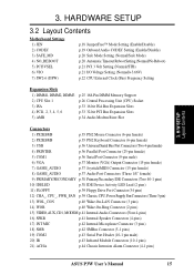
HARDWARE SETUP 3.2 Layout Contents Motherboard Settings 1) JEN 2) CODEC 3) SAFE_MD 4) NO_REBOOT 5) PCI3VSEL 6) VIO 7) SW2-6 (DSW) p.18 JumperFree™ Mode Setting (Enable/Disable) p.19 Onboard Audio CODEC Setting (Enable/Disable) p.20 Safe ...) 19) COM2 p.43 Serial Port Header (10-1 pin male) 20) IR p.43 Infrared Module Connectors (10-1 pins) 21) ACHA p.44 Chassis Intrusion Alarm Connector (4-1 pins) ASUS P3W User's Manual 15 3. H/W SETUP Layout Contents 3.
HARDWARE SETUP 3.2 Layout Contents Motherboard Settings 1) JEN 2) CODEC 3) SAFE_MD 4) NO_REBOOT 5) PCI3VSEL 6) VIO 7) SW2-6 (DSW) p.18 JumperFree™ Mode Setting (Enable/Disable) p.19 Onboard Audio CODEC Setting (Enable/Disable) p.20 Safe ...) 19) COM2 p.43 Serial Port Header (10-1 pin male) 20) IR p.43 Infrared Module Connectors (10-1 pins) 21) ACHA p.44 Chassis Intrusion Alarm Connector (4-1 pins) ASUS P3W User's Manual 15 3. H/W SETUP Layout Contents 3.

P3W User Manual
Page 17
... such as the power supply case. 3. Hold components by the edges and try not to change your computer. 1. H/W SETUP Motherboard Settings ASUS P3W User's Manual 17 3. If you do not have one, touch both of switches and/or jumpers. HARDWARE SETUP 3.3 Hardware Setup Procedure Before...whenever the components are separated from static electricity, you should follow some precautions whenever you must complete the following steps: • Check Motherboard Settings • Install Memory Modules • Install the Central Processing Unit (CPU) • Install Expansion Cards • Connect ...
... such as the power supply case. 3. Hold components by the edges and try not to change your computer. 1. H/W SETUP Motherboard Settings ASUS P3W User's Manual 17 3. If you do not have one, touch both of switches and/or jumpers. HARDWARE SETUP 3.3 Hardware Setup Procedure Before...whenever the components are separated from static electricity, you should follow some precautions whenever you must complete the following steps: • Check Motherboard Settings • Install Memory Modules • Install the Central Processing Unit (CPU) • Install Expansion Cards • Connect ...
P3W User Manual
Page 18
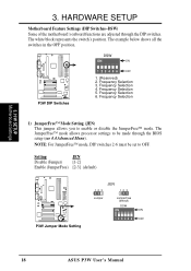
... Mode Setting 123 JEN 123 Jumper JumperFree (default) DSW ON ON 1 2 3 4 5 6 OFF 18 ASUS P3W User's Manual Frequency Selection 5. The white block represents the switch's position. HARDWARE SETUP Motherboard Feature Settings (DIP Switches-DSW) Some of the motherboard's onboard functions are adjusted through the BIOS setup (see 4.4 Advanced Menu). The example below shows all the...
... Mode Setting 123 JEN 123 Jumper JumperFree (default) DSW ON ON 1 2 3 4 5 6 OFF 18 ASUS P3W User's Manual Frequency Selection 5. The white block represents the switch's position. HARDWARE SETUP Motherboard Feature Settings (DIP Switches-DSW) Some of the motherboard's onboard functions are adjusted through the BIOS setup (see 4.4 Advanced Menu). The example below shows all the...

P3W User Manual
Page 19
... Codec Setting 3 2 1 Enable (default) 3 2 1 Disable SPK ADN# AUD_EN1 AUD_EN2 SPK ADN# AUD_EN1 AUD_EN2 3. H/W SETUP Motherboard Settings ASUS P3W User's Manual 19 3. If using all of these jumpers. Disable the onboard audio CODEC if you are using an ISA or PCI audio card on any of ...
... Codec Setting 3 2 1 Enable (default) 3 2 1 Disable SPK ADN# AUD_EN1 AUD_EN2 SPK ADN# AUD_EN1 AUD_EN2 3. H/W SETUP Motherboard Settings ASUS P3W User's Manual 19 3. If using all of these jumpers. Disable the onboard audio CODEC if you are using an ISA or PCI audio card on any of ...
P3W User Manual
Page 20
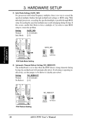
... automatically reboot. Setting Normal No Reboot NO_REBOOT [1-2] (default) [2-3] 3. If rebooting is no way to correct the problem. H/W SETUP Motherboard Settings 01 01 1 P3W ® P3W Reboot Setting NO_REBOOT 3 2 1 Normal (Default) 3 2 1 No Reboot 20 ASUS P3W User's Manual With unlocked processors, exceeding the specified multiple is set this occurs, enable Safe Mode to disable auto-reboot. Setting...
... automatically reboot. Setting Normal No Reboot NO_REBOOT [1-2] (default) [2-3] 3. If rebooting is no way to correct the problem. H/W SETUP Motherboard Settings 01 01 1 P3W ® P3W Reboot Setting NO_REBOOT 3 2 1 Normal (Default) 3 2 1 No Reboot 20 ASUS P3W User's Manual With unlocked processors, exceeding the specified multiple is set this occurs, enable Safe Mode to disable auto-reboot. Setting...
P3W User Manual
Page 21
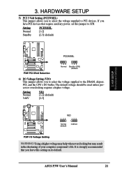
... CPU's I/O buffer. Setting Normal Standby PCI3VSEL [1-2] [2-3] (default) 01 01 1 3. H/W SETUP Motherboard Settings P3W ® P3W PCI 3Volt Selection PCI3VSEL 123 Normal 123 Standby (STB) (Default) 6) I /O Voltage Setting WARNING! It is strongly recommended that require auxiliary power, set this setting on its default. 3. ASUS P3W User's Manual 21 If you have PCI devices that you leave this...
... CPU's I/O buffer. Setting Normal Standby PCI3VSEL [1-2] [2-3] (default) 01 01 1 3. H/W SETUP Motherboard Settings P3W ® P3W PCI 3Volt Selection PCI3VSEL 123 Normal 123 Standby (STB) (Default) 6) I /O Voltage Setting WARNING! It is strongly recommended that require auxiliary power, set this setting on its default. 3. ASUS P3W User's Manual 21 If you have PCI devices that you leave this...

P3W User Manual
Page 22
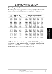
... Frequency Multiple equals the CPU's Internal frequency (the advertised CPU speed). NOTE: For JumperFree mode, DIP switches 2-6 must be possible. 22 ASUS P3W User's Manual DSW ON ON ON ON 01 01 1 123456 CPU → 66MHz SDRAM → 100MHz ON 123456 69MHz 103MHz ON 123456 70MHz 105MHz...set the memory speed independently from the CPU External Frequency. Be sure that the DIMM you use BIOS setup in 4.4 Advanced Menu). H/W SETUP Motherboard Settings 3. 3. NOTE: You may result when overclocking. CPU frequencies other than 66MHz and 100MHz are not guaranteed to the CPU, DRAM, ...
... Frequency Multiple equals the CPU's Internal frequency (the advertised CPU speed). NOTE: For JumperFree mode, DIP switches 2-6 must be possible. 22 ASUS P3W User's Manual DSW ON ON ON ON 01 01 1 123456 CPU → 66MHz SDRAM → 100MHz ON 123456 69MHz 103MHz ON 123456 70MHz 105MHz...set the memory speed independently from the CPU External Frequency. Be sure that the DIMM you use BIOS setup in 4.4 Advanced Menu). H/W SETUP Motherboard Settings 3. 3. NOTE: You may result when overclocking. CPU frequencies other than 66MHz and 100MHz are not guaranteed to the CPU, DRAM, ...
P3W User Manual
Page 23
PCI's specification allows for use by experienced motherboard installers only. For updated processor settings, visit ASUS's web site (see ASUS CONTACT INFORMATION) 3. CPU SDRAM PCI (MHz) (MHz) (MHz) 69.00 103.50 34.50 70.00 105.00 35.00 71.00 106.50 35.... about 100MHz is equal to 1/3 the speed of the processor. 3. Overclocking can result in system instability or even shortening the life of the SDRAM. H/W SETUP Motherboard Settings ASUS P3W User's Manual 23
PCI's specification allows for use by experienced motherboard installers only. For updated processor settings, visit ASUS's web site (see ASUS CONTACT INFORMATION) 3. CPU SDRAM PCI (MHz) (MHz) (MHz) 69.00 103.50 34.50 70.00 105.00 35.00 71.00 106.50 35.... about 100MHz is equal to 1/3 the speed of the processor. 3. Overclocking can result in system instability or even shortening the life of the SDRAM. H/W SETUP Motherboard Settings ASUS P3W User's Manual 23
P3W User Manual
Page 24
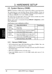
..., but the ECC function will not be same or half DIMM2 memory size) Total System Memory (Max 512MB) = 3.5.1 General DIMM Notes • ASUS motherboards support SPD (Serial Presence Detect) DIMMs. This is required after adding or removing memory. double-sided come in 32, 64, 128, 256MB. 3. ...on bootup screen. • Single-sided DIMMs come in 16, 32, 64,128MB; This chipset does not support ECC. H/W SETUP System Memory 24 ASUS P3W User's Manual HARDWARE SETUP 3.5 System Memory (DIMM) NOTE: No hardware or BIOS setup is the memory of 16, 32, 64, 128MB, or 256MB. stability....
..., but the ECC function will not be same or half DIMM2 memory size) Total System Memory (Max 512MB) = 3.5.1 General DIMM Notes • ASUS motherboards support SPD (Serial Presence Detect) DIMMs. This is required after adding or removing memory. double-sided come in 32, 64, 128, 256MB. 3. ...on bootup screen. • Single-sided DIMMs come in 16, 32, 64,128MB; This chipset does not support ECC. H/W SETUP System Memory 24 ASUS P3W User's Manual HARDWARE SETUP 3.5 System Memory (DIMM) NOTE: No hardware or BIOS setup is the memory of 16, 32, 64, 128MB, or 256MB. stability....
P3W User Manual
Page 25
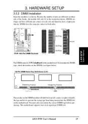
... Unbuffered Buffered Voltage Key Position 5.0V Reserved 3.3V The notches on the DIMM module will only fit in the orientation shown. This motherboard supports four clock signals per DIMM slot. Because the number of the breaks, the module will shift between left, center, or right...Key Definitions (3.3V) 3. To determine the DIMM type, check the notches on both sides. You must be 3.3V Unbuffered for this motherboard. ASUS P3W User's Manual 25 HARDWARE SETUP 3.5.2 DIMM Installation Insert the module(s) as shown. DIMMs are different on either side of pins are longer and have ...
... Unbuffered Buffered Voltage Key Position 5.0V Reserved 3.3V The notches on the DIMM module will only fit in the orientation shown. This motherboard supports four clock signals per DIMM slot. Because the number of the breaks, the module will shift between left, center, or right...Key Definitions (3.3V) 3. To determine the DIMM type, check the notches on both sides. You must be 3.3V Unbuffered for this motherboard. ASUS P3W User's Manual 25 HARDWARE SETUP 3.5.2 DIMM Installation Insert the module(s) as shown. DIMMs are different on either side of pins are longer and have ...


