P3W User Manual
Page 7
... ASUS Motherboard (1) Universal Retention Mechanism for SECC2/SECC/SEPP processors (1) 40-pin 80-conductor ribbon cable for internal UltraDMA/66 or UltraDMA/ 33 IDE drives (1) Ribbon cable for (1) 5.25" and (2) 3.5" floppy disk drives (1) Serial COM2 connector with bracket (1) Bag of spare jumper caps (1) Support CD with drivers and utilities (1) This Motherboard User's Manual ASUS consumer infrared set (optional) ASUS IrDA-compliant infrared module (optional) ASUS S370 Series CPU card (optional) ASUS PCI-L101 Wake-On-LAN 10/100 ethernet card (optional) ASUS P3W User's Manual 7 INTRODUCTION...
... ASUS Motherboard (1) Universal Retention Mechanism for SECC2/SECC/SEPP processors (1) 40-pin 80-conductor ribbon cable for internal UltraDMA/66 or UltraDMA/ 33 IDE drives (1) Ribbon cable for (1) 5.25" and (2) 3.5" floppy disk drives (1) Serial COM2 connector with bracket (1) Bag of spare jumper caps (1) Support CD with drivers and utilities (1) This Motherboard User's Manual ASUS consumer infrared set (optional) ASUS IrDA-compliant infrared module (optional) ASUS S370 Series CPU card (optional) ASUS PCI-L101 Wake-On-LAN 10/100 ethernet card (optional) ASUS P3W User's Manual 7 INTRODUCTION...
P3W User Manual
Page 8
... direct connections between the 810 chipset and subsystems such as SCSI or LAN cards). • Latest Low Pin Count Multi-I/O: Provides two high-speed UART compatible serial ports and one 16-bit ISA expansion slot for the demanding PC user who wants many smart features in cards. • Multi-Cache! Supports Wake-On-LAN, Wake-On-Ring, Keyboard Wake-Up, and BIOS Wake-Up. 8 ASUS P3W User's Manual So what's so smart about 12% performance over that of jumpers...
... direct connections between the 810 chipset and subsystems such as SCSI or LAN cards). • Latest Low Pin Count Multi-I/O: Provides two high-speed UART compatible serial ports and one 16-bit ISA expansion slot for the demanding PC user who wants many smart features in cards. • Multi-Cache! Supports Wake-On-LAN, Wake-On-Ring, Keyboard Wake-Up, and BIOS Wake-Up. 8 ASUS P3W User's Manual So what's so smart about 12% performance over that of jumpers...
P3W User Manual
Page 9
... power is removed and through the ASUS ASIC. ASUS P3W User's Manual 9 FEATURES Optional Component(s) 2. Hardware random number generator supports new security software for virtually automatic setup. • Smart BIOS! 4Mbit firmware gives a new easy-to-use interface which provides more control and protection over the motherboard. 2. Supports chassis intrusion monitoring through a new design, battery drain is even lower than the RTC used for your PC's Health! Programmable BIOS (Flash EEPROM), offering enhanced ACPI for Windows 98 compatibility...
... power is removed and through the ASUS ASIC. ASUS P3W User's Manual 9 FEATURES Optional Component(s) 2. Hardware random number generator supports new security software for virtually automatic setup. • Smart BIOS! 4Mbit firmware gives a new easy-to-use interface which provides more control and protection over the motherboard. 2. Supports chassis intrusion monitoring through a new design, battery drain is even lower than the RTC used for your PC's Health! Programmable BIOS (Flash EEPROM), offering enhanced ACPI for Windows 98 compatibility...
P3W User Manual
Page 10
... Mode 2), PIO Modes 3 & 4, and supports Enhanced IDE devices, such as required by PC'99. • Highest Audio Quality! ACPI (Advanced Configuration and Power Interface) is also implemented on the following high-level goals: Support for Plug and Play compatibility and power management for Windows 95/98/NT. The integrated motion compensation allows for an exciting gameplay experience. 10 ASUS P3W User's Manual The best of +90dB. ASUS smart series motherboards support the new generation memory...
... Mode 2), PIO Modes 3 & 4, and supports Enhanced IDE devices, such as required by PC'99. • Highest Audio Quality! ACPI (Advanced Configuration and Power Interface) is also implemented on the following high-level goals: Support for Plug and Play compatibility and power management for Windows 95/98/NT. The integrated motion compensation allows for an exciting gameplay experience. 10 ASUS P3W User's Manual The best of +90dB. ASUS smart series motherboards support the new generation memory...
P3W User Manual
Page 11
.... • Dual Function Power Button! CPU temperature is monitored by the internal thermal diode is the actual processor core temperature as the "Standby" (a.k.a. Voltage specifications are used up can access any information from anywhere in . ASUS P3W User's Manual 11 Regardless of the setting, pushing the power button for RPM and failure. With this benefit on managing their computers from their limited resources more than 4 seconds will enter the Soft-Off mode. • Remote...
.... • Dual Function Power Button! CPU temperature is monitored by the internal thermal diode is the actual processor core temperature as the "Standby" (a.k.a. Voltage specifications are used up can access any information from anywhere in . ASUS P3W User's Manual 11 Regardless of the setting, pushing the power button for RPM and failure. With this benefit on managing their computers from their limited resources more than 4 seconds will enter the Soft-Off mode. • Remote...

P3W User Manual
Page 15
... IDE Connectors (Two 40-1 pins) 10) IDELED p.38 IDE Device Activity LED Lead (2 pins) 11) FLOPPY p.39 Floppy Drive Port Connector (34 pins) 12) CHA_, CPU_, PWR_FAN p.39 Chassis, CPU, Power Supply Fan Connectors (Three 3-pin) 13) WOL_CON p.40 Wake-On-LAN Connector (3 pins) 14) WOR p.40 Wake-On-Ring Connector (2 pins) 15) VIDEO,AUX, CD1, MODEM p.41 Internal Audio Connectors (Four 4-pins) 16) SPKR p.41 Internal Speaker Connectors (4-pins) 17) INT MIC p.42 Internal Microphone Connector (3 pins) 18) SMB p.42 SMBus Connector (5-1 pins) 19) COM2 p.43 Serial Port Header (10-1 pin...
... IDE Connectors (Two 40-1 pins) 10) IDELED p.38 IDE Device Activity LED Lead (2 pins) 11) FLOPPY p.39 Floppy Drive Port Connector (34 pins) 12) CHA_, CPU_, PWR_FAN p.39 Chassis, CPU, Power Supply Fan Connectors (Three 3-pin) 13) WOL_CON p.40 Wake-On-LAN Connector (3 pins) 14) WOR p.40 Wake-On-Ring Connector (2 pins) 15) VIDEO,AUX, CD1, MODEM p.41 Internal Audio Connectors (Four 4-pins) 16) SPKR p.41 Internal Speaker Connectors (4-pins) 17) INT MIC p.42 Internal Microphone Connector (3 pins) 18) SMB p.42 SMBus Connector (5-1 pins) 19) COM2 p.43 Serial Port Header (10-1 pin...
P3W User Manual
Page 20
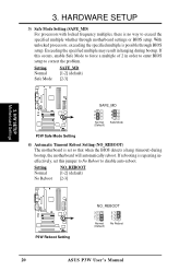
... enter BIOS setup to disable auto-reboot. H/W SETUP Motherboard Settings 01 01 1 P3W ® P3W Reboot Setting NO_REBOOT 3 2 1 Normal (Default) 3 2 1 No Reboot 20 ASUS P3W User's Manual If this jumper to No Reboot to correct the problem. HARDWARE SETUP 3) Safe Mode Setting (SAFE_MD) For processors with locked frequency multiples, there is set this occurs, enable Safe Mode to exceed the specified multiple whether through BIOS setup. Setting Normal Safe Mode SAFE_MD [1-2] (default) [2-3] 01 01 1 P3W ® SAFE_MD 3 2 1 Normal (Default) 3 2 1 Safe Mode P3W Safe...
... enter BIOS setup to disable auto-reboot. H/W SETUP Motherboard Settings 01 01 1 P3W ® P3W Reboot Setting NO_REBOOT 3 2 1 Normal (Default) 3 2 1 No Reboot 20 ASUS P3W User's Manual If this jumper to No Reboot to correct the problem. HARDWARE SETUP 3) Safe Mode Setting (SAFE_MD) For processors with locked frequency multiples, there is set this occurs, enable Safe Mode to exceed the specified multiple whether through BIOS setup. Setting Normal Safe Mode SAFE_MD [1-2] (default) [2-3] 01 01 1 P3W ® SAFE_MD 3 2 1 Normal (Default) 3 2 1 Safe Mode P3W Safe...
P3W User Manual
Page 38
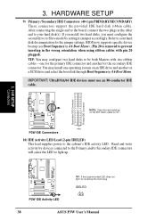
... IDE connector and another on the IDE ribbon cable to PIN 1 PIN 1 P3W IDE Connectors 10) IDE Activity LED Lead (2-pin IDELED) This lead supplies power to Slave mode by devices connected to the Primary and/or Secondary IDE connectors will cause the LED to your hard disk(s). Read and write activity by setting its jumper accordingly. BIOS now supports specific device bootup (see Boot Sequence in 4.6 Boot Menu). (Pin 20 is removed to prevent inserting in 4.6 Boot Menu. IMPORTANT: UltraDMA/66 IDE devices must configure the second drive...
... IDE connector and another on the IDE ribbon cable to PIN 1 PIN 1 P3W IDE Connectors 10) IDE Activity LED Lead (2-pin IDELED) This lead supplies power to Slave mode by devices connected to the Primary and/or Secondary IDE connectors will cause the LED to your hard disk(s). Read and write activity by setting its jumper accordingly. BIOS now supports specific device bootup (see Boot Sequence in 4.6 Boot Menu). (Pin 20 is removed to prevent inserting in 4.6 Boot Menu. IMPORTANT: UltraDMA/66 IDE devices must configure the second drive...

P3W User Manual
Page 45
... the BIOS but the keyboard will turn off . This function requires ACPI OS and driver support. ASUS P3W User's Manual 45 3. H/W SETUP Connectors P3W System Panel Connectors Message LED SMI Lead Reset SW ATX Power Switch* 22) System Power LED Lead (3-1 pin KEYLOCK) This 3-1 pin connector connects the system power LED, which lights when the system is powered on the position of certain components when the system is used for more than 4 seconds will always allow keyboard locking. 24) System Warning Speaker Connector (4-pin SPEAKER) This 4-pin connector connects...
... the BIOS but the keyboard will turn off . This function requires ACPI OS and driver support. ASUS P3W User's Manual 45 3. H/W SETUP Connectors P3W System Panel Connectors Message LED SMI Lead Reset SW ATX Power Switch* 22) System Power LED Lead (3-1 pin KEYLOCK) This 3-1 pin connector connects the system power LED, which lights when the system is powered on the position of certain components when the system is used for more than 4 seconds will always allow keyboard locking. 24) System Warning Speaker Connector (4-pin SPEAKER) This 4-pin connector connects...

P3W User Manual
Page 47
... case according to enter BIOS setup. The power LED on the screen. While the tests are made, close the system case cover. 2. The power supply should turn off the power switch. ASUS P3W User's Manual 47 Recheck your jumper settings and connections or call your computer" will not appear when shutting down your system user's manual. 4. For ATX power supplies, the system LED will then run power-on the chain) c. After all switches are using Windows 95/98, click the Start button...
... case according to enter BIOS setup. The power LED on the screen. While the tests are made, close the system case cover. 2. The power supply should turn off the power switch. ASUS P3W User's Manual 47 Recheck your jumper settings and connections or call your computer" will not appear when shutting down your system user's manual. 4. For ATX power supplies, the system LED will then run power-on the chain) c. After all switches are using Windows 95/98, click the Start button...
P3W User Manual
Page 48
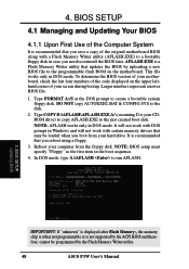
... memory drivers that you reboot using a floppy. 3. It is a Flash Memory Writer utility that you save a copy of your CDROM drive) to copy AFLASH.EXE to run AFLASH. 4. BIOS SETUP Updating BIOS IMPORTANT! To determine the BIOS version of your motherboard, check the last four numbers of the code displayed on the motherboard. NOTE: AFLASH works only in DOS mode. AFLASH.EXE is recommended that updates the BIOS by the Flash Memory Writer utility. 48 ASUS P3W User's Manual...
... memory drivers that you reboot using a floppy. 3. It is a Flash Memory Writer utility that you save a copy of your CDROM drive) to copy AFLASH.EXE to run AFLASH. 4. BIOS SETUP Updating BIOS IMPORTANT! To determine the BIOS version of your motherboard, check the last four numbers of the code displayed on the motherboard. NOTE: AFLASH works only in DOS mode. AFLASH.EXE is recommended that updates the BIOS by the Flash Memory Writer utility. 48 ASUS P3W User's Manual...
P3W User Manual
Page 57
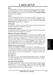
...] [16 Sectors] [32 Sectors] [Maximum] SMART Monitoring [Disabled] This allows the enabling or disabling of read/write heads. BIOS SETUP Head This field configures the number of the S.M.A.R.T. (Self-Monitoring, Analysis and Reporting Technology) system which utilizes internal hard disk drive monitoring technology. Configuration options: [0] [1] [2] [3] [4] [Disabled] 4. Refer to your drive documentation to determine the correct value to suppress Ultra DMA capability. This field can also be set a PIO (Programmed Input/Output) mode for compatible IDE devices. 4.
...] [16 Sectors] [32 Sectors] [Maximum] SMART Monitoring [Disabled] This allows the enabling or disabling of read/write heads. BIOS SETUP Head This field configures the number of the S.M.A.R.T. (Self-Monitoring, Analysis and Reporting Technology) system which utilizes internal hard disk drive monitoring technology. Configuration options: [0] [1] [2] [3] [4] [Disabled] 4. Refer to your drive documentation to determine the correct value to suppress Ultra DMA capability. This field can also be set a PIO (Programmed Input/Output) mode for compatible IDE devices. 4.
P3W User Manual
Page 61
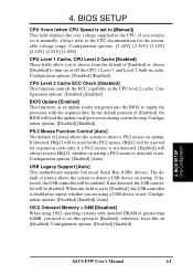
...cache. Configuration options: [Disabled] [Enabled] BIOS Update [Enabled] This functions as an update loader integrated into the BIOS to the CPU documentation for expansion cards only if a PS/2 mouse is detected or not. IRQ12 will load the update on startup. When this on or off the CPU's Level 1 and Level 2 built-in the CPU level 2 cache. Configuration options: [Disabled] [Enabled] 4. Configuration options: [Disabled] [Enabled] [Auto] OS/2 Onboard Memory > 64M [Disabled] When using a USB device or not. BIOS SETUP Chip Configuration ASUS P3W User's Manual 61 In the default position...
...cache. Configuration options: [Disabled] [Enabled] BIOS Update [Enabled] This functions as an update loader integrated into the BIOS to the CPU documentation for expansion cards only if a PS/2 mouse is detected or not. IRQ12 will load the update on startup. When this on or off the CPU's Level 1 and Level 2 built-in the CPU level 2 cache. Configuration options: [Disabled] [Enabled] 4. Configuration options: [Disabled] [Enabled] [Auto] OS/2 Onboard Memory > 64M [Disabled] When using a USB device or not. BIOS SETUP Chip Configuration ASUS P3W User's Manual 61 In the default position...
P3W User Manual
Page 65
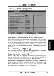
...If a modem/audio device is detected, the onboard modem/audio controller will be disabled. 4. if no modem/audio device is detected, the onboard modem/audio controller will be enabled; BIOS SETUP I /O Device Configuration 4. Configuration options: [3F8H/ IRQ4] [2F8H/IRQ3] [3E8H/IRQ4] [2E8H/IRQ10] [Disabled] ASUS P3W User's Manual 65 BIOS SETUP 4.4.2 I /O Device Config (scroll down to see more items, as shown here) Onboard AC97 Modem Controller, Audio Controller [Auto] [Auto] allows the motherboard's BIOS to reverse the hardware drive letter assignments of your floppy disk drives.
...If a modem/audio device is detected, the onboard modem/audio controller will be disabled. 4. if no modem/audio device is detected, the onboard modem/audio controller will be enabled; BIOS SETUP I /O Device Configuration 4. Configuration options: [3F8H/ IRQ4] [2F8H/IRQ3] [3E8H/IRQ4] [2E8H/IRQ10] [Disabled] ASUS P3W User's Manual 65 BIOS SETUP 4.4.2 I /O Device Config (scroll down to see more items, as shown here) Onboard AC97 Modem Controller, Audio Controller [Auto] [Auto] allows the motherboard's BIOS to reverse the hardware drive letter assignments of your floppy disk drives.
P3W User Manual
Page 67
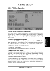
... PCI/VGA Palette Snoop [Disabled] Some nonstandard VGA cards, such as graphics accelerators or MPEG video cards, may not show colors properly. If your Symbios SCSI card does not have a Symbios SCSI card. BIOS SETUP 4.4.3 PCI Configuration 4. Configuration options: [Auto] [Disabled] ASUS P3W User's Manual 67 BIOS SETUP PCI Configuration Slot 1/5, Slot 2, Slot 3/6, Slot 4 IRQ [Auto] These fields set how IRQ use . Configuration options: [Disabled] [Enabled] PCI Latency Timer [32] Leave on default setting for each PCI slot. if no Symbios SCSI card is detected, the motherboard...
... PCI/VGA Palette Snoop [Disabled] Some nonstandard VGA cards, such as graphics accelerators or MPEG video cards, may not show colors properly. If your Symbios SCSI card does not have a Symbios SCSI card. BIOS SETUP 4.4.3 PCI Configuration 4. Configuration options: [Auto] [Disabled] ASUS P3W User's Manual 67 BIOS SETUP PCI Configuration Slot 1/5, Slot 2, Slot 3/6, Slot 4 IRQ [Auto] These fields set how IRQ use . Configuration options: [Disabled] [Enabled] PCI Latency Timer [32] Leave on default setting for each PCI slot. if no Symbios SCSI card is detected, the motherboard...
P3W User Manual
Page 68
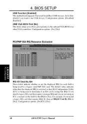
... the onboard VGA BIOS over other VGA controllers. If you install a legacy ISA card that IRQ to use USB devices. BIOS SETUP USB Function [Enabled] This motherboard supports Universal Serial Bus (USB) devices. The default value indicates either that the displayed IRQ is not used or that ISA Configuration Utility (ICU) is being used to [Yes]. For example: If you install a legacy ISA card that IRQ. 4. Configuration options: [No] [Yes] PCI/PNP ISA IRQ Resource Exclusion 4. Configuration options: [Disabled] [Enabled] ONB VGA BIOS First [No] This field, when set IRQ10 Used...
... the onboard VGA BIOS over other VGA controllers. If you install a legacy ISA card that IRQ to use USB devices. BIOS SETUP USB Function [Enabled] This motherboard supports Universal Serial Bus (USB) devices. The default value indicates either that the displayed IRQ is not used or that ISA Configuration Utility (ICU) is being used to [Yes]. For example: If you install a legacy ISA card that IRQ. 4. Configuration options: [No] [Yes] PCI/PNP ISA IRQ Resource Exclusion 4. Configuration options: [Disabled] [Enabled] ONB VGA BIOS First [No] This field, when set IRQ10 Used...
P3W User Manual
Page 82
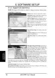
... to monitor your onboard components to help you update your BIOS or download a BIOS image file. Driver: Installs the necessary drivers for your computer's fan, temperature, and voltages. Network Driver Setup: Not available on this motherboard. YAMAHA S-YXG50: Installs Yamaha's software synthesizer for playing MIDI files on this motherboard. ASUS LiveUpdate: Installs a program to work properly. Other INF Update Utility for 810 Chipset: This utility installs INF files in Windows for the following items: System and Graphics, LPC Interface, SM Bus, PCI Bridge, Bus Master IDE, USB...
... to monitor your onboard components to help you update your BIOS or download a BIOS image file. Driver: Installs the necessary drivers for your computer's fan, temperature, and voltages. Network Driver Setup: Not available on this motherboard. YAMAHA S-YXG50: Installs Yamaha's software synthesizer for playing MIDI files on this motherboard. ASUS LiveUpdate: Installs a program to work properly. Other INF Update Utility for 810 Chipset: This utility installs INF files in Windows for the following items: System and Graphics, LPC Interface, SM Bus, PCI Bridge, Bus Master IDE, USB...
P3W User Manual
Page 83
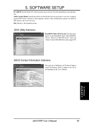
.... DOS Utility Submenu Flash BIOS Utility (DOS Version): Provides information on the support CD. ASUS Contact Information Submenu This page gives Marketing and Technical Support contact information which is available in PDF format. Choose "Restart in MS-DOS mode" then type "aflash" from the AFLASH folder on the Flash BIOS utility (AFLASH.EXE). 5. SOFTWARE SETUP PC-cillin 98: Installs Trend's PC-cillin virus protection software. S/W SETUP Windows 98 ASUS P3W User's Manual 83 Exit...
.... DOS Utility Submenu Flash BIOS Utility (DOS Version): Provides information on the support CD. ASUS Contact Information Submenu This page gives Marketing and Technical Support contact information which is available in PDF format. Choose "Restart in MS-DOS mode" then type "aflash" from the AFLASH folder on the Flash BIOS utility (AFLASH.EXE). 5. SOFTWARE SETUP PC-cillin 98: Installs Trend's PC-cillin virus protection software. S/W SETUP Windows 98 ASUS P3W User's Manual 83 Exit...
P3W User Manual
Page 105
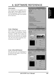
...) This is not supported. Internet links are also available for easy access to the ASUS Web page for the desktop but this applies to your graphics device such as the color adjustments for new updated drivers and notices. In 16-color and 8-bit color (standard color, 256-color) modes, the gamma correction function is the same as chipset, memory, BIOS, and drivers. 6. Gamma correction...
...) This is not supported. Internet links are also available for easy access to the ASUS Web page for the desktop but this applies to your graphics device such as the color adjustments for new updated drivers and notices. In 16-color and 8-bit color (standard color, 256-color) modes, the gamma correction function is the same as chipset, memory, BIOS, and drivers. 6. Gamma correction...
P3W User Manual
Page 122
... Floppy Disk Access Control 65 Floppy Disk Drive Connector 39 Full Screen Logo 77 H Halt On 59 Hardware Information 116 HDD Power Down 72 Head 57 Headers Serial Port COM 2 43 High Priority PCI Mode 64 I IDE Activity LED Lead 38 IDE Hard Drive 76 INF Update Utility for 810 Chipset 93, 94 Installation Memory 25 Installed Memory 59 Intel Security Driver 95 Internal Audio Connectors 41 Internal Microphone Connector 42 Internal Speaker Connector 41 Interrupts Request Table 33 Standard Assignments 32 IRQ XX Used By ISA 68 ISA Cards...
... Floppy Disk Access Control 65 Floppy Disk Drive Connector 39 Full Screen Logo 77 H Halt On 59 Hardware Information 116 HDD Power Down 72 Head 57 Headers Serial Port COM 2 43 High Priority PCI Mode 64 I IDE Activity LED Lead 38 IDE Hard Drive 76 INF Update Utility for 810 Chipset 93, 94 Installation Memory 25 Installed Memory 59 Intel Security Driver 95 Internal Audio Connectors 41 Internal Microphone Connector 42 Internal Speaker Connector 41 Interrupts Request Table 33 Standard Assignments 32 IRQ XX Used By ISA 68 ISA Cards...


