
P3V4X User Manual
Page 1
® P3V4X ATX Motherboard USER'S MANUAL
® P3V4X ATX Motherboard USER'S MANUAL
P3V4X User Manual
Page 4
INTRODUCTION 7 1.1 How This Manual Is Organized 7 1.2 Item Checklist 7 2. FEATURES 8 2.1 The ASUS P3V4X 8 2.1.1 Specifications 8 2.1.2 Special Features 10 2.1.3 Performance Features 10 2.1.4 Intelligence 11 2.2 P3V4X Motherboard Components 12 3. HARDWARE SETUP 14 3.1 P3V4X Motherboard Layout 14 3.2 Layout Contents 15 3.3 Hardware Setup Procedure 16 3.4 Motherboard Settings 16 3.5 System Memory (DIMM 20 3.6 Central ... First Use of the Computer System 43 4.1.2 Updating BIOS Procedures (only when necessary) ......... 44 4 ASUS P3V4X User's Manual CONTENTS 1.
INTRODUCTION 7 1.1 How This Manual Is Organized 7 1.2 Item Checklist 7 2. FEATURES 8 2.1 The ASUS P3V4X 8 2.1.1 Specifications 8 2.1.2 Special Features 10 2.1.3 Performance Features 10 2.1.4 Intelligence 11 2.2 P3V4X Motherboard Components 12 3. HARDWARE SETUP 14 3.1 P3V4X Motherboard Layout 14 3.2 Layout Contents 15 3.3 Hardware Setup Procedure 16 3.4 Motherboard Settings 16 3.5 System Memory (DIMM 20 3.6 Central ... First Use of the Computer System 43 4.1.2 Updating BIOS Procedures (only when necessary) ......... 44 4 ASUS P3V4X User's Manual CONTENTS 1.
P3V4X User Manual
Page 5
... 85 7. APPENDIX 89 7.1 S370 Series CPU Cards 89 7.1.1 Using the ASUS S370 Series CPU Cards 90 7.1.2 Setting up the ASUS S370 Series CPU Cards 90 7.2 ASUS PCI-L101 Fast Ethernet Card 91 7.3 Glossary 93 ASUS P3V4X User's Manual 5 CONTENTS 4.2 BIOS Setup Program 47 4.2.1 BIOS Menu Bar 48 4.2.2 ... 74 4.7 Exit Menu 75 5. SOFTWARE SETUP 77 5.1 Operating Systems 77 5.1.1 Windows 98 First Time Installation 77 5.2 P3V Series Motherboard Support CD 78 5.3 Install ASUS PC Probe Vx.xx 79 5.4 Install PC-Cillin 98 Vx.xx 80 5.5 Install ADOBE AcroBat Reader Vx.xx 80 5.6 VIA ...
... 85 7. APPENDIX 89 7.1 S370 Series CPU Cards 89 7.1.1 Using the ASUS S370 Series CPU Cards 90 7.1.2 Setting up the ASUS S370 Series CPU Cards 90 7.2 ASUS PCI-L101 Fast Ethernet Card 91 7.3 Glossary 93 ASUS P3V4X User's Manual 5 CONTENTS 4.2 BIOS Setup Program 47 4.2.1 BIOS Menu Bar 48 4.2.2 ... 74 4.7 Exit Menu 75 5. SOFTWARE SETUP 77 5.1 Operating Systems 77 5.1.1 Windows 98 First Time Installation 77 5.2 P3V Series Motherboard Support CD 78 5.3 Install ASUS PC Probe Vx.xx 79 5.4 Install PC-Cillin 98 Vx.xx 80 5.5 Install ADOBE AcroBat Reader Vx.xx 80 5.6 VIA ...
P3V4X User Manual
Page 7
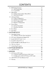
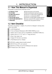
... disk drives (1) Bag of spare jumper caps (1) Support CD with drivers and utilities (1) This Motherboard User's Manual ASUS IrDA-compliant infrared module (optional) ASUS S370 Series CPU cards (optional) ASUS PCI-L101 Wake-On-LAN 10/100 Ethernet Card (optional) CPU thermal sensor cable (optional) ASUS P3V4X User's Manual 7 INTRODUCTION 2. 1. INTRODUCTION 1.1 How This Manual Is Organized This manual is complete.
... disk drives (1) Bag of spare jumper caps (1) Support CD with drivers and utilities (1) This Motherboard User's Manual ASUS IrDA-compliant infrared module (optional) ASUS S370 Series CPU cards (optional) ASUS PCI-L101 Wake-On-LAN 10/100 Ethernet Card (optional) CPU thermal sensor cable (optional) ASUS P3V4X User's Manual 7 INTRODUCTION 2. 1. INTRODUCTION 1.1 How This Manual Is Organized This manual is complete.

P3V4X User Manual
Page 8
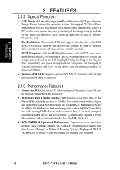
VC SDRAM and HSDRAM are included to allow manual adjustment of the processor's external frequency. • Multi-Cache: Supports processors with 512, 256, 128, or 0KB Pipelined Burst Level 2 cache. • AGP Slot: Supports ... jumpers are new DRAM core architectures that support four IDE devices on two channels. Easy-to-use DIP switches instead of frequency through an optional ASUS PCI-L101 10/100 Fast Ethernet PCI card (see 7. FEATURES 2.1 The ASUS P3V4X The ASUS P3V4X motherboard is enabled. Appendix). 8 ASUS P3V4X User's Manual 2. FEATURES Specifications 2.
VC SDRAM and HSDRAM are included to allow manual adjustment of the processor's external frequency. • Multi-Cache: Supports processors with 512, 256, 128, or 0KB Pipelined Burst Level 2 cache. • AGP Slot: Supports ... jumpers are new DRAM core architectures that support four IDE devices on two channels. Easy-to-use DIP switches instead of frequency through an optional ASUS PCI-L101 10/100 Fast Ethernet PCI card (see 7. FEATURES 2.1 The ASUS P3V4X The ASUS P3V4X motherboard is enabled. Appendix). 8 ASUS P3V4X User's Manual 2. FEATURES Specifications 2.
P3V4X User Manual
Page 10
... or Enhanced Memory System's High-speed DRAMs (HSDRAMs) for operating systems that supports autodetection of ASUS smart series motherboards meet PC'98 compliancy. FEATURES Performance 2. This motherboard with existing DMA devices and systems so there is backward compatible with both DMA/33 and DMA ...ACPI Ready: Advanced Configuration Power Interface (ACPI) provides more Energy Saving Features for higher system performance at minimal cost premium. 10 ASUS P3V4X User's Manual To fully utilize the benefits of ACPI, an ACPI-supported OS, such as Windows 98 must be ready around the clock,...
... or Enhanced Memory System's High-speed DRAMs (HSDRAMs) for operating systems that supports autodetection of ASUS smart series motherboards meet PC'98 compliancy. FEATURES Performance 2. This motherboard with existing DMA devices and systems so there is backward compatible with both DMA/33 and DMA ...ACPI Ready: Advanced Configuration Power Interface (ACPI) provides more Energy Saving Features for higher system performance at minimal cost premium. 10 ASUS P3V4X User's Manual To fully utilize the benefits of ACPI, an ACPI-supported OS, such as Windows 98 must be ready around the clock,...
P3V4X User Manual
Page 11
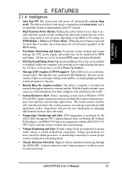
... now act as Windows 95/98/ NT and OS/2, require much more protection. With this benefit on remotely through the ASUS ASIC. ASUS P3V4X User's Manual 11 2. FEATURES Intelligence 2. Voltage specifications are monitored to ensure stable voltage to prevent possible application crashes. When the power ... to be powered on Pentium III, Pentium II (Deschutes), and PPGA370 Celeron in the mailbox. All fans are used up to critical motherboard components. A simple glimpse provides useful information to the user. • Remote Ring On (requires modem): This allows a computer to ...
... now act as Windows 95/98/ NT and OS/2, require much more protection. With this benefit on remotely through the ASUS ASIC. ASUS P3V4X User's Manual 11 2. FEATURES Intelligence 2. Voltage specifications are monitored to ensure stable voltage to prevent possible application crashes. When the power ... to be powered on Pentium III, Pentium II (Deschutes), and PPGA370 Celeron in the mailbox. All fans are used up to critical motherboard components. A simple glimpse provides useful information to the user. • Remote Ring On (requires modem): This allows a computer to ...
P3V4X User Manual
Page 12
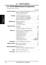
Location Processor Support Slot 1 for locations. FEATURES P3V4X Components 2. 2. FEATURES 2.2 P3V4X Motherboard Components See opposite page for Coppermine/Katmai/Mendecino Processors ...... 2 66MHz to 150MHz bus support (16 external clock settings) Chipsets VIA VT82C694X System Controller 3 VIA VT82C596B ... 13 Hardware Monitoring Hardware Monitor 7 3 Fan Power and Speed Monitoring Connectors Power ATX Power Supply Connector 1 Form Factor ATX, 19.2cm x 30.5cm (7.6" x 12") 12 ASUS P3V4X User's Manual
Location Processor Support Slot 1 for locations. FEATURES P3V4X Components 2. 2. FEATURES 2.2 P3V4X Motherboard Components See opposite page for Coppermine/Katmai/Mendecino Processors ...... 2 66MHz to 150MHz bus support (16 external clock settings) Chipsets VIA VT82C694X System Controller 3 VIA VT82C596B ... 13 Hardware Monitoring Hardware Monitor 7 3 Fan Power and Speed Monitoring Connectors Power ATX Power Supply Connector 1 Form Factor ATX, 19.2cm x 30.5cm (7.6" x 12") 12 ASUS P3V4X User's Manual
P3V4X User Manual
Page 13
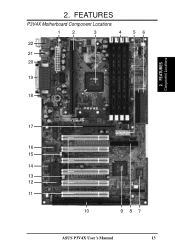
FEATURES Component Locations 17 16 15 14 13 12 11 10 987 ASUS P3V4X User's Manual 13 2. FEATURES P3V4X Motherboard Component Locations 1 2 3 4 22 21 20 56 19 18 2.
FEATURES Component Locations 17 16 15 14 13 12 11 10 987 ASUS P3V4X User's Manual 13 2. FEATURES P3V4X Motherboard Component Locations 1 2 3 4 22 21 20 56 19 18 2.
P3V4X User Manual
Page 14
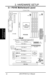
H/W SETUP Motherboard Layout 3. HARDWARE SETUP 3.1 P3V4X Motherboard Layout 19.2cm (7.6in) T: Mouse B: Keyboard PS2KBMS USB T: USB1 B: USB2 COM1 CPU_FAN PWR_FAN PARALLEL PORT ATX Power Connector CPU Slot 1 VIA VT82C694X Chipset COM2 JTPWR P3V4X CLRTC CR2032 3V Lithium Cell (CMOS Power) Row 0 1 2 3 4 5 6 7 R Accelerated Graphics Port PLED2 PCI Slot ... Slot 4 WOR PCI Slot 5 PCI Slot 6 ISA Slot FLOPPY VIA VT82C596B Chipset ASUS ASIC with Hardware Monitor CHA_FAN PANEL JEN IDELED IR 14 ASUS P3V4X User's Manual DIMM Socket 0 (64/72 bit, 168 pin module) DIMM Socket 1 (64/...
H/W SETUP Motherboard Layout 3. HARDWARE SETUP 3.1 P3V4X Motherboard Layout 19.2cm (7.6in) T: Mouse B: Keyboard PS2KBMS USB T: USB1 B: USB2 COM1 CPU_FAN PWR_FAN PARALLEL PORT ATX Power Connector CPU Slot 1 VIA VT82C694X Chipset COM2 JTPWR P3V4X CLRTC CR2032 3V Lithium Cell (CMOS Power) Row 0 1 2 3 4 5 6 7 R Accelerated Graphics Port PLED2 PCI Slot ... Slot 4 WOR PCI Slot 5 PCI Slot 6 ISA Slot FLOPPY VIA VT82C596B Chipset ASUS ASIC with Hardware Monitor CHA_FAN PANEL JEN IDELED IR 14 ASUS P3V4X User's Manual DIMM Socket 0 (64/72 bit, 168 pin module) DIMM Socket 1 (64/...
P3V4X User Manual
Page 15
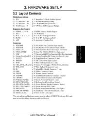
H/W SETUP Layout Contents 3. ASUS P3V4X User's Manual 15 3. HARDWARE SETUP 3.2 Layout Contents Motherboard Settings 1) JEN 2) U12-Switches 5 & 6 3) U12-Switches 7-10 4) U12-Switches 1-4 p. 17 JumperFree™ Mode (Enable/Disable) p. 17 AGP Bus Frequency Setting p. 18... IR p. 37 Infrared Port Module Connector (5 pins) 13) SMB p. 38 SMBus Connector (3 pins) 14) JTPWR p. 38 Thermal Sensor Connector 15) ATXPWR p. 39 ATX Motherboard Power Connector (20 pins) 16) CHASSIS p. 39 Chassis Intrusion Alarm Lead (4-1 pins) 17) PWR.LED (PANEL) p. 40 System Power LED Lead (3-1 pins) 18) ...
H/W SETUP Layout Contents 3. ASUS P3V4X User's Manual 15 3. HARDWARE SETUP 3.2 Layout Contents Motherboard Settings 1) JEN 2) U12-Switches 5 & 6 3) U12-Switches 7-10 4) U12-Switches 1-4 p. 17 JumperFree™ Mode (Enable/Disable) p. 17 AGP Bus Frequency Setting p. 18... IR p. 37 Infrared Port Module Connector (5 pins) 13) SMB p. 38 SMBus Connector (3 pins) 14) JTPWR p. 38 Thermal Sensor Connector 15) ATXPWR p. 39 ATX Motherboard Power Connector (20 pins) 16) CHASSIS p. 39 Chassis Intrusion Alarm Lead (4-1 pins) 17) PWR.LED (PANEL) p. 40 System Power LED Lead (3-1 pins) 18) ...
P3V4X User Manual
Page 16
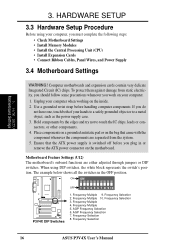
...Expansion Cards • Connect Ribbon Cables, Panel Wires, and Power Supply 3.4 Motherboard Settings WARNING! Motherboard Feature Settings (U12) The motherboard's onboard functions are separated from static electricity, you should follow some precautions whenever...Selection 2. Frequency Multiple 10. AGP Frequency Selection 6. ON ON P3V4X R P3V4X DIP Switches OFF 1 2 3 4 5 6 7 8 9 10 1. AGP Frequency Selection 7. Frequency Selection 16 ASUS P3V4X User's Manual H/W SETUP Motherboard Settings 3. Frequency Multiple 5. HARDWARE SETUP 3.3 Hardware Setup Procedure Before...
...Expansion Cards • Connect Ribbon Cables, Panel Wires, and Power Supply 3.4 Motherboard Settings WARNING! Motherboard Feature Settings (U12) The motherboard's onboard functions are separated from static electricity, you should follow some precautions whenever...Selection 2. Frequency Multiple 10. AGP Frequency Selection 6. ON ON P3V4X R P3V4X DIP Switches OFF 1 2 3 4 5 6 7 8 9 10 1. AGP Frequency Selection 7. Frequency Selection 16 ASUS P3V4X User's Manual H/W SETUP Motherboard Settings 3. Frequency Multiple 5. HARDWARE SETUP 3.3 Hardware Setup Procedure Before...

P3V4X User Manual
Page 17
...to OFF. ON ON 1 2 3 4 5 6 7 8 9 10 1 2 3 4 5 6 7 8 9 10 P3V4X AGP Bus Freq. x1 =DRAM Freq. x1/2 P3V4X AGP Bus Frequency Setting ASUS P3V4X User's Manual 17 JumperFree™ Mode (JEN) This jumper allows you to be made through the BIOS setup (see 4.4 Advanced Menu). Setting JEN...[1-2] P3V4X R JEN 123 123 Jumper JumperFree P3V4X Jumper Mode Setting 2. AGP Bus Frequency Setting (U12-Switches 5&6) This option sets the frequency ratio between the AGP bus frequency and the DRAM (CPU bus) frquency. See the processor table on the following page. H/W SETUP Motherboard Settings ...
...to OFF. ON ON 1 2 3 4 5 6 7 8 9 10 1 2 3 4 5 6 7 8 9 10 P3V4X AGP Bus Freq. x1 =DRAM Freq. x1/2 P3V4X AGP Bus Frequency Setting ASUS P3V4X User's Manual 17 JumperFree™ Mode (JEN) This jumper allows you to be made through the BIOS setup (see 4.4 Advanced Menu). Setting JEN...[1-2] P3V4X R JEN 123 123 Jumper JumperFree P3V4X Jumper Mode Setting 2. AGP Bus Frequency Setting (U12-Switches 5&6) This option sets the frequency ratio between the AGP bus frequency and the DRAM (CPU bus) frquency. See the processor table on the following page. H/W SETUP Motherboard Settings ...
P3V4X User Manual
Page 18
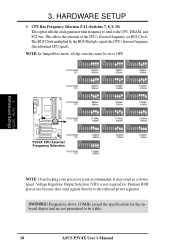
...7 8 9 10 112MHz 37MHz ON ON ON 1 2 3 4 5 6 7 8 9 10 CPU/DRAM PCI 68MHz 34MHz ON 1 2 3 4 5 6 7 8 9 10 100MHz 33MHz ON 1 2 3 4 5 6 7 8 9 10 120MHz 40MHz ON P3V4X 1 2 3 4 5 6 7 8 9 10 1 2 3 4 5 6 7 8 9 10 1 2 3 4 5 6 7 8 9 10 R CPU/DRAM 115MHz 110MHz 105MHz PCI 38MHz 36MHz 35MHz ON ON ON 1 2 3 4 5 6 7 ...ASUS P3V4X User's Manual Frequencies above 133MHz exceed the specifications for Pentium III/II processors because they send signals directly to the CPU, DRAM, and PCI bus. 3. This allows the selection of the CPU's External frequency (or BUS Clock). H/W SETUP Motherboard...
...7 8 9 10 112MHz 37MHz ON ON ON 1 2 3 4 5 6 7 8 9 10 CPU/DRAM PCI 68MHz 34MHz ON 1 2 3 4 5 6 7 8 9 10 100MHz 33MHz ON 1 2 3 4 5 6 7 8 9 10 120MHz 40MHz ON P3V4X 1 2 3 4 5 6 7 8 9 10 1 2 3 4 5 6 7 8 9 10 1 2 3 4 5 6 7 8 9 10 R CPU/DRAM 115MHz 110MHz 105MHz PCI 38MHz 36MHz 35MHz ON ON ON 1 2 3 4 5 6 7 ...ASUS P3V4X User's Manual Frequencies above 133MHz exceed the specifications for Pentium III/II processors because they send signals directly to the CPU, DRAM, and PCI bus. 3. This allows the selection of the CPU's External frequency (or BUS Clock). H/W SETUP Motherboard...
P3V4X User Manual
Page 19
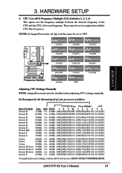
...2 3 4 5 6 7 8 9 10 1 2 3 4 5 6 7 8 9 10 3.5x(7/2) 4.0x(4/1) 4.5x(9/2) ON ON ON P3V4X R 1 2 3 4 5 6 7 8 9 10 1 2 3 4 5 6 7 8 9 10 1 2 3 4 5 6 7 8 9 10 5.0x(5/1) 5.5x(11/2) 6.0x(6/1) ON ON ON P3V4X CPU : BUS Frequency Multiple 1 2 3 4 5 6 7 8 9 10 6.5x(13/2) ON 1 2 3 4 5 6 7 8 9...ASUS web site (see ASUS CONTACT INFORMATION) ASUS P3V4X User's Manual 19 HARDWARE SETUP 4. These must be set to OFF. Mult. Multiple) AGP Freq. 3. H/W SETUP Motherboard Settings Adjusting CPU Settings Manually NOTE: JumperFree mode must be disabled when adjusting CPU settings manually...
...2 3 4 5 6 7 8 9 10 1 2 3 4 5 6 7 8 9 10 3.5x(7/2) 4.0x(4/1) 4.5x(9/2) ON ON ON P3V4X R 1 2 3 4 5 6 7 8 9 10 1 2 3 4 5 6 7 8 9 10 1 2 3 4 5 6 7 8 9 10 5.0x(5/1) 5.5x(11/2) 6.0x(6/1) ON ON ON P3V4X CPU : BUS Frequency Multiple 1 2 3 4 5 6 7 8 9 10 6.5x(13/2) ON 1 2 3 4 5 6 7 8 9...ASUS web site (see ASUS CONTACT INFORMATION) ASUS P3V4X User's Manual 19 HARDWARE SETUP 4. These must be set to OFF. Mult. Multiple) AGP Freq. 3. H/W SETUP Motherboard Settings Adjusting CPU Settings Manually NOTE: JumperFree mode must be disabled when adjusting CPU settings manually...
P3V4X User Manual
Page 20
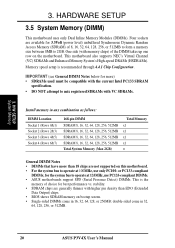
... 256MB; One side (with VC SDRAMs. Install memory in 32, 64, 128, 256, or 512MB. 20 ASUS P3V4X User's Manual Four sockets are generally thinner with higher pin density than 18 chips are not supported on the motherboard. IMPORTANT (see General DIMM Notes below for more than EDO (Extended Data Output) chips. • BIOS...
... 256MB; One side (with VC SDRAMs. Install memory in 32, 64, 128, 256, or 512MB. 20 ASUS P3V4X User's Manual Four sockets are generally thinner with higher pin density than 18 chips are not supported on the motherboard. IMPORTANT (see General DIMM Notes below for more than EDO (Extended Data Output) chips. • BIOS...
P3V4X User Manual
Page 21
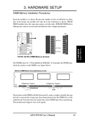
... correct DIMM type before purchasing. H/W SETUP System Memory DRAM Key Position RFU Unbuffered Buffered Voltage Key Position 5.0V Reserved 3.3V The notches on the motherboard. ASUS P3V4X User's Manual 21 Because the number of pins are different on either side of the breaks, the module will shift between left, center, or right to identify... Installation Procedures: Insert the module(s) as shown. You must be 3.3Volt unbuffered SDRAMs. To determine the DIMM type, check the notches on both sides. This motherboard supports four clock signals.
... correct DIMM type before purchasing. H/W SETUP System Memory DRAM Key Position RFU Unbuffered Buffered Voltage Key Position 5.0V Reserved 3.3V The notches on the motherboard. ASUS P3V4X User's Manual 21 Because the number of pins are different on either side of the breaks, the module will shift between left, center, or right to identify... Installation Procedures: Insert the module(s) as shown. You must be 3.3Volt unbuffered SDRAMs. To determine the DIMM type, check the notches on both sides. This motherboard supports four clock signals.
P3V4X User Manual
Page 23
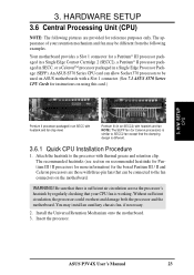
... Celeron processors) is different. 3.6.1 Quick CPU Installation Procedure 1. Without sufficient circulation, the processor could overheat and damage both the processor and the motherboard. Insert the processor. ASUS P3V4X User's Manual 23 An ASUS S370 Series CPU card can allow Socket 370 processors to the processor with thermal grease and retention clip. WARNING! Be sure that...
... Celeron processors) is different. 3.6.1 Quick CPU Installation Procedure 1. Without sufficient circulation, the processor could overheat and damage both the processor and the motherboard. Insert the processor. ASUS P3V4X User's Manual 23 An ASUS S370 Series CPU card can allow Socket 370 processors to the processor with thermal grease and retention clip. WARNING! Be sure that...
P3V4X User Manual
Page 25
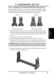
...With Integrated Retainer Pins and (B) With Separate Retainer Pins. 3. HARDWARE SETUP 3.6.3 Installing the Universal Retention Mechanism Your motherboard comes with the motherboard. Position the retention mechanism on the anti-static foam that the top retainer pins are not pushed in will not...URM), which supports Pentium III / II and Celeron processors. H/W SETUP CPU ASUS P3V4X User's Manual 25 Place the motherboard on either side of the motherboard. 2. Push the four retainer pins completely down on the motherboard. 3. Making sure that was shipped with a set of each pin is ...
...With Integrated Retainer Pins and (B) With Separate Retainer Pins. 3. HARDWARE SETUP 3.6.3 Installing the Universal Retention Mechanism Your motherboard comes with the motherboard. Position the retention mechanism on the anti-static foam that the top retainer pins are not pushed in will not...URM), which supports Pentium III / II and Celeron processors. H/W SETUP CPU ASUS P3V4X User's Manual 25 Place the motherboard on either side of the motherboard. 2. Push the four retainer pins completely down on the motherboard. 3. Making sure that was shipped with a set of each pin is ...
P3V4X User Manual
Page 26
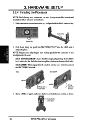
... engaged, the T-bars lock into place. Locked Position (push upward) 26 ASUS P3V4X User's Manual H/W SETUP CPU 3. SECC SECC2/SEPP Lock hole CPU fan cable to fan connector Lock hole CPU fan cable to the connector or else misalignment will occur. If your motherboard. 1. Connector Key Substrate Key 2. Push down firmly but gently the...
... engaged, the T-bars lock into place. Locked Position (push upward) 26 ASUS P3V4X User's Manual H/W SETUP CPU 3. SECC SECC2/SEPP Lock hole CPU fan cable to fan connector Lock hole CPU fan cable to the connector or else misalignment will occur. If your motherboard. 1. Connector Key Substrate Key 2. Push down firmly but gently the...


