P2L97 User Manual
Page 1
R P2L97 Pentium® II Motherboard USER'S MANUAL
R P2L97 Pentium® II Motherboard USER'S MANUAL
P2L97 User Manual
Page 4
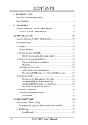
... 25 ISA Cards and Hardware Monitor 25 5. Jumpers 12 Jumper Settings 13 2. FEATURES 8 Features of the ASUS P2L97 Motherboard 10 Installation Steps 12 1. External Connectors 26 Power Connection Procedures 33 Main Menu 34 IV. INTRODUCTION 7 How this Manual is Organized 7 Item Checklist 7 II. System Memory (DIMM 17 DIMM Memory Installation Procedures 18 3. BIOS SOFTWARE...
... 25 ISA Cards and Hardware Monitor 25 5. Jumpers 12 Jumper Settings 13 2. FEATURES 8 Features of the ASUS P2L97 Motherboard 10 Installation Steps 12 1. External Connectors 26 Power Connection Procedures 33 Main Menu 34 IV. INTRODUCTION 7 How this Manual is Organized 7 Item Checklist 7 II. System Memory (DIMM 17 DIMM Memory Installation Procedures 18 3. BIOS SOFTWARE...

P2L97 User Manual
Page 7
...: I. INTRODUCTION How this product Instructions on setting up the motherboard and jumper Instructions on setting up the BIOS software Item Checklist Check that your retailer. (1) ASUS Motherboard (1) Univeral retention mechanism for SECC/SECC2/SEPP (1) IDE ribbon... Support CD with drivers and utilities (1) Motherboard user's manual Infrared module (optional) ASUS PCI-SC200 Fast-SCSI or PCI-SC860 Ultra-Fast SCSI card (optional) ASUS P2L97 User's Manual 7 INTRODUCTION (Manual / Checklist) I . BIOS Software Manual information and checklist Information and specifications concerning this...
...: I. INTRODUCTION How this product Instructions on setting up the motherboard and jumper Instructions on setting up the BIOS software Item Checklist Check that your retailer. (1) ASUS Motherboard (1) Univeral retention mechanism for SECC/SECC2/SEPP (1) IDE ribbon... Support CD with drivers and utilities (1) Motherboard user's manual Infrared module (optional) ASUS PCI-SC200 Fast-SCSI or PCI-SC860 Ultra-Fast SCSI card (optional) ASUS P2L97 User's Manual 7 INTRODUCTION (Manual / Checklist) I . BIOS Software Manual information and checklist Information and specifications concerning this...
P2L97 User Manual
Page 8
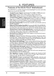
.... • Super Multi-I/O: Provides two high-speed UART compatible serial ports and one parallel port with EPP and ECP capabilities. FEATURES Features of the ASUS P2L97 Motherboard The ASUS P2L97 is carefully designed for the demanding PC user who wants many features processed by the fastest CPU. • Versatile Processor Support: Intel Pentium® II... allows multiple PCI transfers from PCI master busses to memory to make setup of hard drives, PS/2 mouse, and Plug and Play devices to CPU. 8 ASUS P2L97 User's Manual FEATURES (Specifications) II. II.
.... • Super Multi-I/O: Provides two high-speed UART compatible serial ports and one parallel port with EPP and ECP capabilities. FEATURES Features of the ASUS P2L97 Motherboard The ASUS P2L97 is carefully designed for the demanding PC user who wants many features processed by the fastest CPU. • Versatile Processor Support: Intel Pentium® II... allows multiple PCI transfers from PCI master busses to memory to make setup of hard drives, PS/2 mouse, and Plug and Play devices to CPU. 8 ASUS P2L97 User's Manual FEATURES (Specifications) II. II.

P2L97 User Manual
Page 9
FEATURES The ASUS P2L97 Motherboard T: PS/2 Mouse B: PS/2 Keyboard T: USB Port 1 B: USB Port 2 B: COM 1 T: Parallel B: Serial B: COM 2 Intel 440LX AGPset 3 DIMM Sockets Accelerated Graphics Port 4 PCI Slots Programmable Flash ROM 1 ISA/PCI Share 1 ISA Slot ASUS P2L97 User's Manual 9 FEATURES (Motherboard Parts) II. II.
FEATURES The ASUS P2L97 Motherboard T: PS/2 Mouse B: PS/2 Keyboard T: USB Port 1 B: USB Port 2 B: COM 1 T: Parallel B: Serial B: COM 2 Intel 440LX AGPset 3 DIMM Sockets Accelerated Graphics Port 4 PCI Slots Programmable Flash ROM 1 ISA/PCI Share 1 ISA Slot ASUS P2L97 User's Manual 9 FEATURES (Motherboard Parts) II. II.
P2L97 User Manual
Page 10
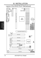
... Connector IDE LED Panel Connectors 10 ASUS P2L97 User's Manual DIMM Socket 1 (64/72 bit, 168 pin module) DIMM Socket 2 (64/72 bit, 168 pin module) DIMM Socket 3 (64/72 bit, 168 pin module) ATX Power Conenctor Single Edge Contact CPU Slot III. INSTALLATION Layout of the ASUS P2L97 Motherboard PS/2 Top: Mouse Bottom: Keyboard KB_UP...
... Connector IDE LED Panel Connectors 10 ASUS P2L97 User's Manual DIMM Socket 1 (64/72 bit, 168 pin module) DIMM Socket 2 (64/72 bit, 168 pin module) DIMM Socket 3 (64/72 bit, 168 pin module) ATX Power Conenctor Single Edge Contact CPU Slot III. INSTALLATION Layout of the ASUS P2L97 Motherboard PS/2 Top: Mouse Bottom: Keyboard KB_UP...
P2L97 User Manual
Page 11
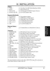
...) 9) CHA_, PWR_, CPU_FAN p. 29 Chassis, Power Supply, CPU Fan Power Lead (3-pin block) 10) IR p. 30 Infrared Port Module Connector (5 pins) 11) ATXPWR p. 30 ATX Motherboard Power Connector (20-pin block) 12) WOL p. 31 Wake on LAN Connector (3 pins) (Reserved) 13) MSG LED (PANEL) p. 32 System Message LED (2 pins) 14) SMI... Output Connector (4 pins) *The onboard hardware monitor uses the address 290H-297H so legacy ISA cards must not use this address otherwise conflicts will occur. ASUS P2L97 User's Manual 11 INSTALLATION (Board Layout) III.
...) 9) CHA_, PWR_, CPU_FAN p. 29 Chassis, Power Supply, CPU Fan Power Lead (3-pin block) 10) IR p. 30 Infrared Port Module Connector (5 pins) 11) ATXPWR p. 30 ATX Motherboard Power Connector (20-pin block) 12) WOL p. 31 Wake on LAN Connector (3 pins) (Reserved) 13) MSG LED (PANEL) p. 32 System Message LED (2 pins) 14) SMI... Output Connector (4 pins) *The onboard hardware monitor uses the address 290H-297H so legacy ISA cards must not use this address otherwise conflicts will occur. ASUS P2L97 User's Manual 11 INSTALLATION (Board Layout) III.
P2L97 User Manual
Page 12
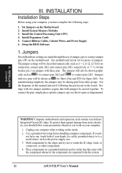
... as diagrammed. INSTALLATION (Jumpers) WARNING! To protect them against damage from other components. 4. Setup the BIOS Software 1. See motherboard layout for locations of your hands to a safely grounded object or to connect pins 2&3. A "1" is written besides pin 1 on the board....cally such as [----], [1-2], [2-3] for Open (Off). Use the diagrams in this manual instead of following steps: 1. III. Jumpers Several hardware settings are separated from the system. 12 ASUS P2L97 User's Manual To connect the pins, simply place a plastic jumper cap over the two pins ...
... as diagrammed. INSTALLATION (Jumpers) WARNING! To protect them against damage from other components. 4. Setup the BIOS Software 1. See motherboard layout for locations of your hands to a safely grounded object or to connect pins 2&3. A "1" is written besides pin 1 on the board....cally such as [----], [1-2], [2-3] for Open (Off). Use the diagrams in this manual instead of following steps: 1. III. Jumpers Several hardware settings are separated from the system. 12 ASUS P2L97 User's Manual To connect the pins, simply place a plastic jumper cap over the two pins ...
P2L97 User Manual
Page 17
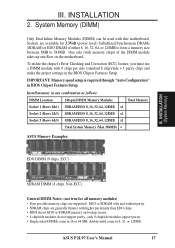
...double-sided come in the BIOS Chipset Features Setup. ASUS P2L97 User's Manual 17 Install memory in BIOS Chipset Features Setup. To utilize the chipset's Error Checking and Correction (ECC) feature, you must use a DIMM module with this motherboard. Sockets are available for all memory modules) &#...SDRAM/EDO 8, 16, 32, 64, 128MB x1 Socket 3 (Rows 4&5) SDRAM/EDO 8, 16, 32, 64, 128MB x1 Total System Memory (Max 384MB) = ASUS Memory Examples: EDO DIMM (9 chips, ECC) III. INSTALLATION 2. System Memory (DIMM) Only Dual Inline Memory Modules (DIMM) can be used with 9 chips per side...
...double-sided come in the BIOS Chipset Features Setup. ASUS P2L97 User's Manual 17 Install memory in BIOS Chipset Features Setup. To utilize the chipset's Error Checking and Correction (ECC) feature, you must use a DIMM module with this motherboard. Sockets are available for all memory modules) &#...SDRAM/EDO 8, 16, 32, 64, 128MB x1 Socket 3 (Rows 4&5) SDRAM/EDO 8, 16, 32, 64, 128MB x1 Total System Memory (Max 384MB) = ASUS Memory Examples: EDO DIMM (9 chips, ECC) III. INSTALLATION 2. System Memory (DIMM) Only Dual Inline Memory Modules (DIMM) can be used with 9 chips per side...

P2L97 User Manual
Page 18
... will only fit in the orientation as shown. Four clock signals are supported on either side of pins are different on this motherboard. 18 ASUS P2L97 User's Manual SDRAM DIMM modules have different pint contact on each side and therefore have the same pin contact on the... motherboard. INSTALLATION DIMM Memory Installation Procedures: Insert the module(s) as shown. Because the number of the breaks, the module will shift between left, center...
... will only fit in the orientation as shown. Four clock signals are supported on either side of pins are different on this motherboard. 18 ASUS P2L97 User's Manual SDRAM DIMM modules have different pint contact on each side and therefore have the same pin contact on the... motherboard. INSTALLATION DIMM Memory Installation Procedures: Insert the module(s) as shown. Because the number of the breaks, the module will shift between left, center...

P2L97 User Manual
Page 19
... necessary. III. III. INSTALLATION CPU Universal Retention Mechanism (URM) Heatsinks The recommended heatsinks (see section on the motherboard. WARNING! Without sufficient circulation, the processor could overheat and damage both the processor and the motherboard. ASUS P2L97 User's Manual 19 Pentium II processor packaged in an SECC with a Universal Retention Mechanism (URM). Central Processing Unit (CPU...
... necessary. III. III. INSTALLATION CPU Universal Retention Mechanism (URM) Heatsinks The recommended heatsinks (see section on the motherboard. WARNING! Without sufficient circulation, the processor could overheat and damage both the processor and the motherboard. ASUS P2L97 User's Manual 19 Pentium II processor packaged in an SECC with a Universal Retention Mechanism (URM). Central Processing Unit (CPU...
P2L97 User Manual
Page 21
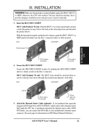
otherwise, the CPU will overheat. INSTALLATION CPU CPU fan cable to fan connector CPU fan cable to your motherboard's thermal sensor connector. (See next page for information on the Slot 1 connector. SECC with Pentium® II only: Push the SECC's... circulation across the processor's passive heatsink. 3. Make sure the heatsink is firmly seated on ASUS Smart Thermal Solutions.) ASUS P2L97 User's Manual 21 SECC SECC2/SEPP Push lock inward III. III. With the heatsink facing the motherboard's chipset, push the SECC, SECC2, or SEPP gently but firmly into the Slot 1 ...
otherwise, the CPU will overheat. INSTALLATION CPU CPU fan cable to fan connector CPU fan cable to your motherboard's thermal sensor connector. (See next page for information on the Slot 1 connector. SECC with Pentium® II only: Push the SECC's... circulation across the processor's passive heatsink. 3. Make sure the heatsink is firmly seated on ASUS Smart Thermal Solutions.) ASUS P2L97 User's Manual 21 SECC SECC2/SEPP Push lock inward III. III. With the heatsink facing the motherboard's chipset, push the SECC, SECC2, or SEPP gently but firmly into the Slot 1 ...
P2L97 User Manual
Page 23
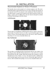
... still be included in the package, in case you use a heatsink without a fan. ASUS P2L97 User's Manual 23 AAVID Heatsink The procedures for Pentium II Processors The heatsinks shown in the orientation as ... preceding procedure. You will , however, still be connected to the preceding procedure. Mount the heatsink in this manual are those with the hardware monitor, the ability to clamp the heatsink into the SEC cartridge. III. INSTALLATION... is also similar to the CPU fan connector on the motherboard. INSTALLATION CPU The procedures for reference purposes only.
... still be included in the package, in case you use a heatsink without a fan. ASUS P2L97 User's Manual 23 AAVID Heatsink The procedures for Pentium II Processors The heatsinks shown in the orientation as ... preceding procedure. You will , however, still be connected to the preceding procedure. Mount the heatsink in this manual are those with the hardware monitor, the ability to clamp the heatsink into the SEC cartridge. III. INSTALLATION... is also similar to the CPU fan connector on the motherboard. INSTALLATION CPU The procedures for reference purposes only.

P2L97 User Manual
Page 24
... (MSD.EXE) utility located in any necessary hardware or software settings for expansion cards. You may use at the same time. 24 ASUS P2L97 User's Manual If you intend to both your expansion card, such as legacy ISA cards, requires that no two devices share the same IRQs or ...system components. Secure the card on the slot you use IRQs. Ensure that you removed above. 5. Currently, there are two types of your motherboard has audio onboard, an extra 3 IRQs will experience problems when those two devices are available to use Windows 95, the Resources tab under Device...
... (MSD.EXE) utility located in any necessary hardware or software settings for expansion cards. You may use at the same time. 24 ASUS P2L97 User's Manual If you intend to both your expansion card, such as legacy ISA cards, requires that no two devices share the same IRQs or ...system components. Secure the card on the slot you use IRQs. Ensure that you removed above. 5. Currently, there are two types of your motherboard has audio onboard, an extra 3 IRQs will experience problems when those two devices are available to use Windows 95, the Resources tab under Device...
P2L97 User Manual
Page 25
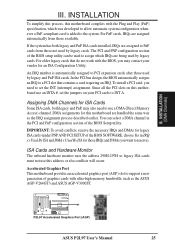
... ISA cards. Accelerated Graphics Port This motherboard provides an accelerated graphics port (AGP) slot to set the jumpers on your vendor for ISA Cards Some ISA cards, both legacy and PnP ISA cards installed, IRQs are being used by legacy cards. R P2L97 Accelerated Graphics Port (AGP) ASUS P2L97 User's Manual 25 III. If the system...
... ISA cards. Accelerated Graphics Port This motherboard provides an accelerated graphics port (AGP) slot to set the jumpers on your vendor for ISA Cards Some ISA cards, both legacy and PnP ISA cards installed, IRQs are being used by legacy cards. R P2L97 Accelerated Graphics Port (AGP) ASUS P2L97 User's Manual 25 III. If the system...

P2L97 User Manual
Page 26
...the second drive connector no more than 6in. (15cm) from jumpers in BIOS Features Setup of the Motherboard." You may use IRQ12. PS/2 Mouse (6-pin Female) 26 ASUS P2L97 User's Manual PS/2 Keyboard Connector (6-pin Female) This connection is for connectors or power sources. If not detected,... expansion cards can use a DIN to the PS/2 mouse if one is the side closest to your motherboard. Placing jumper caps over these ...
...the second drive connector no more than 6in. (15cm) from jumpers in BIOS Features Setup of the Motherboard." You may use IRQ12. PS/2 Mouse (6-pin Female) 26 ASUS P2L97 User's Manual PS/2 Keyboard Connector (6-pin Female) This connection is for connectors or power sources. If not detected,... expansion cards can use a DIN to the PS/2 mouse if one is the side closest to your motherboard. Placing jumper caps over these ...
P2L97 User Manual
Page 29
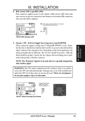
INSTALLATION 8. IDE_LED P2L97 IDE Activity LED 9. Depending on the fan manufacturer, the wiring and plug may occur to the motherboard and/or the CPU fan if these pins. WARNING! The CPU and/or motherboard will cause the LED to the Primary or Secondary IDE connectors will overheat if there is... the board taking into consideration the polarity of 500mAMP (6WATT) or less. Chassis Fan Power CPU Fan Power Power Supply Fan P2L97 12Volt Cooling Fan Power ASUS P2L97 User's Manual 29 Rotation +12V GND III. Orientate the fans so that the heat sink fins allow airflow to be ground.
INSTALLATION 8. IDE_LED P2L97 IDE Activity LED 9. Depending on the fan manufacturer, the wiring and plug may occur to the motherboard and/or the CPU fan if these pins. WARNING! The CPU and/or motherboard will cause the LED to the Primary or Secondary IDE connectors will overheat if there is... the board taking into consideration the polarity of 500mAMP (6WATT) or less. Chassis Fan Power CPU Fan Power Power Supply Fan P2L97 12Volt Cooling Fan Power ASUS P2L97 User's Manual 29 Rotation +12V GND III. Orientate the fans so that the heat sink fins allow airflow to be ground.
P2L97 User Manual
Page 30
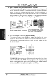
... the proper orientation and push down firmly but gently making sure that your ATX power supply can supply at least 720mA. 30 ASUS P2L97 User's Manual IrDA-Compliant Infrared Module Connector (5-pin IR) This connector supports the optional wireless transmitting and receiving infrared module. You must connect ...the power supply will only insert in Chipset Features Setup to the motherboard 11. The plug from the module to the motherboard according to the pin definitions. (NC) GND +5V IRRX IRTX Front View Back View P2L97 Infrared Module Connector IRTX +5V GND (NC) IRRX For the ...
... the proper orientation and push down firmly but gently making sure that your ATX power supply can supply at least 720mA. 30 ASUS P2L97 User's Manual IrDA-Compliant Infrared Module Connector (5-pin IR) This connector supports the optional wireless transmitting and receiving infrared module. You must connect ...the power supply will only insert in Chipset Features Setup to the motherboard 11. The plug from the module to the motherboard according to the pin definitions. (NC) GND +5V IRRX IRTX Front View Back View P2L97 Infrared Module Connector IRTX +5V GND (NC) IRRX For the ...
P2L97 User Manual
Page 34
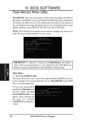
... examples only and may not reflect the screen contents displayed on the upper left-hand corner of the original motherboard BIOS in DOS mode. BIOS SOFTWARE Flash Memory Writer Utility AFLASH.EXE: This is the Flash Memory Writer...reinstall it. This file works only in case you to the programmable flash ROM chip on the motherboard. To save a copy of your motherboard, check the last four numbers of the code displayed on your current BIOS, type [1] at the...Memory Writer) IMPORTANT! Type a filename and the path, for example, A:\XXXXX-X and then press . 34 ASUS P2L97 User's Manual
... examples only and may not reflect the screen contents displayed on the upper left-hand corner of the original motherboard BIOS in DOS mode. BIOS SOFTWARE Flash Memory Writer Utility AFLASH.EXE: This is the Flash Memory Writer...reinstall it. This file works only in case you to the programmable flash ROM chip on the motherboard. To save a copy of your motherboard, check the last four numbers of the code displayed on your current BIOS, type [1] at the...Memory Writer) IMPORTANT! Type a filename and the path, for example, A:\XXXXX-X and then press . 34 ASUS P2L97 User's Manual
P2L97 User Manual
Page 36
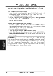
.... IV. Save Current BIOS to the just created boot disk. 3. If this new disk and select option 1. BIOS SOFTWARE Managing and Updating Your Motherboard's BIOS Upon First Use of the steps. Save Current BIOS To File on page 3 for more details and the rest of the steps. Run... successfully update a complete BIOS file, your system will need service. At the Main Menu, type 2 and then press . BIOS (Updating BIOS) 36 ASUS P2L97 User's Manual Just repeat the process, and if the problem still persists, update the original BIOS file you created earlier. 2. At the "A:\" prompt, type AFLASH and...
.... IV. Save Current BIOS to the just created boot disk. 3. If this new disk and select option 1. BIOS SOFTWARE Managing and Updating Your Motherboard's BIOS Upon First Use of the steps. Save Current BIOS To File on page 3 for more details and the rest of the steps. Run... successfully update a complete BIOS file, your system will need service. At the Main Menu, type 2 and then press . BIOS (Updating BIOS) 36 ASUS P2L97 User's Manual Just repeat the process, and if the problem still persists, update the original BIOS file you created earlier. 2. At the "A:\" prompt, type AFLASH and...


