P2L97 User Manual
Page 1
R P2L97 Pentium® II Motherboard USER'S MANUAL
R P2L97 Pentium® II Motherboard USER'S MANUAL
P2L97 User Manual
Page 2
... BEEN ADVISED OF THE POSSIBILITY OF SUCH DAMAGES ARISING FROM ANY DEFECT OR ERROR IN THIS MANUAL OR PRODUCT. Product Name: ASUS P2L97 Manual Revision: 2.05 E266 Release Date: October 1998 2 ASUS P2L97 User's Manual USER'S NOTICE No part of this manual may or may be reproduced, transmitted, transcribed, stored in a retrieval system, or translated into any language...
... BEEN ADVISED OF THE POSSIBILITY OF SUCH DAMAGES ARISING FROM ANY DEFECT OR ERROR IN THIS MANUAL OR PRODUCT. Product Name: ASUS P2L97 Manual Revision: 2.05 E266 Release Date: October 1998 2 ASUS P2L97 User's Manual USER'S NOTICE No part of this manual may or may be reproduced, transmitted, transcribed, stored in a retrieval system, or translated into any language...

P2L97 User Manual
Page 3
...886-2-2894-3447 Fax: +886-2-2894-3449 Email: info@asus.com.tw Technical Support Fax: +886-2-2895-9254 BBS: +886-2-2896-4667 Email: tsd@asus.com.tw WWW: www.asus.com.tw FTP: ftp.asus.com.tw/pub/ASUS ASUS COMPUTER INTERNATIONAL Marketing Address: 6737 Mowry Avenue, Mowry Business Center... 49-2102-445011 Fax: 49-2102-442066 Email: info-ger@asus.com.tw Technical Support Hotline: 49-2102-499712 BBS: 49-2102-448690 Email: tsd-ger@asus.com.tw WWW: www.asuscom.de FTP: ftp.asuscom.de/pub/ASUSCOM ASUS P2L97 User's Manual 3 ASUS CONTACT INFORMATION ASUSTeK COMPUTER INC.
...886-2-2894-3447 Fax: +886-2-2894-3449 Email: info@asus.com.tw Technical Support Fax: +886-2-2895-9254 BBS: +886-2-2896-4667 Email: tsd@asus.com.tw WWW: www.asus.com.tw FTP: ftp.asus.com.tw/pub/ASUS ASUS COMPUTER INTERNATIONAL Marketing Address: 6737 Mowry Avenue, Mowry Business Center... 49-2102-445011 Fax: 49-2102-442066 Email: info-ger@asus.com.tw Technical Support Hotline: 49-2102-499712 BBS: 49-2102-448690 Email: tsd-ger@asus.com.tw WWW: www.asuscom.de FTP: ftp.asuscom.de/pub/ASUSCOM ASUS P2L97 User's Manual 3 ASUS CONTACT INFORMATION ASUSTeK COMPUTER INC.
P2L97 User Manual
Page 4
... 13 2. External Connectors 26 Power Connection Procedures 33 Main Menu 34 IV. INSTALLATION 10 Layout of the ASUS P2L97 Motherboard 8 The ASUS P2L97 Motherboard 9 III. CONTENTS I. Expansion Cards 24 Expansion Card Installation Procedure 24 Assigning IRQs for Expansion Cards 24...Mechanism 19 Heatsinks 19 Installing the Processor 20 ASUS Smart Thermal Solutions 22 Recommended Heatsinks for ISA Cards 25 ISA Cards and Hardware Monitor 25 5. BIOS Setup 37 Load Defaults 38 4 ASUS P2L97 User's Manual System Memory (DIMM 17 DIMM Memory Installation Procedures...
... 13 2. External Connectors 26 Power Connection Procedures 33 Main Menu 34 IV. INSTALLATION 10 Layout of the ASUS P2L97 Motherboard 8 The ASUS P2L97 Motherboard 9 III. CONTENTS I. Expansion Cards 24 Expansion Card Installation Procedure 24 Assigning IRQs for Expansion Cards 24...Mechanism 19 Heatsinks 19 Installing the Processor 20 ASUS Smart Thermal Solutions 22 Recommended Heatsinks for ISA Cards 25 ISA Cards and Hardware Monitor 25 5. BIOS Setup 37 Load Defaults 38 4 ASUS P2L97 User's Manual System Memory (DIMM 17 DIMM Memory Installation Procedures...

P2L97 User Manual
Page 5
CONTENTS Standard CMOS Setup 38 Details of Standard CMOS Setup 38 BIOS Features Setup 41 Details of BIOS Features Setup 41 Chipset Features Setup 44 Details of Chipset Features Setup 44 Power Management Setup 47 Details of Power Management Setup 47 PNP and PCI Setup 50 Details of PNP and PCI Setup 50 Load BIOS Defaults 52 Load Setup Defaults 52 Supervisor Password and User Password 53 IDE HDD Auto Detection 54 Save & Exit Setup 55 Exit Without Saving 55 ASUS P2L97 User's Manual 5
CONTENTS Standard CMOS Setup 38 Details of Standard CMOS Setup 38 BIOS Features Setup 41 Details of BIOS Features Setup 41 Chipset Features Setup 44 Details of Chipset Features Setup 44 Power Management Setup 47 Details of Power Management Setup 47 PNP and PCI Setup 50 Details of PNP and PCI Setup 50 Load BIOS Defaults 52 Load Setup Defaults 52 Supervisor Password and User Password 53 IDE HDD Auto Detection 54 Save & Exit Setup 55 Exit Without Saving 55 ASUS P2L97 User's Manual 5

P2L97 User Manual
Page 6
... to which the receiver is required to provide reasonable protection against harmful interference in the Radio Interference Regulations of the Canadian Department of Communications. 6 ASUS P2L97 User's Manual The use of shielded cables for connection of the monitor to the graphics card is connected. • Consult the dealer or an experienced radio/TV...
... to which the receiver is required to provide reasonable protection against harmful interference in the Radio Interference Regulations of the Canadian Department of Communications. 6 ASUS P2L97 User's Manual The use of shielded cables for connection of the monitor to the graphics card is connected. • Consult the dealer or an experienced radio/TV...

P2L97 User Manual
Page 7
... your retailer. (1) ASUS Motherboard (1) Univeral retention mechanism for SECC/SECC2/SEPP (1) IDE ribbon cable for master and slave drives (1) Floppy ribbon cable (1) Bag of spare jumper caps (1) Support CD with drivers and utilities (1) Motherboard user's manual Infrared module (optional) ASUS PCI-SC200 Fast-SCSI or PCI-SC860 Ultra-Fast SCSI card (optional) ASUS P2L97 User's Manual 7
... your retailer. (1) ASUS Motherboard (1) Univeral retention mechanism for SECC/SECC2/SEPP (1) IDE ribbon cable for master and slave drives (1) Floppy ribbon cable (1) Bag of spare jumper caps (1) Support CD with drivers and utilities (1) Motherboard user's manual Infrared module (optional) ASUS PCI-SC200 Fast-SCSI or PCI-SC860 Ultra-Fast SCSI card (optional) ASUS P2L97 User's Manual 7
P2L97 User Manual
Page 8
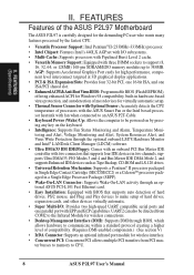
FEATURES Features of the ASUS P2L97 Motherboard The ASUS P2L97 is carefully designed for the demanding PC user who wants many features processed by pressing any key on the keyboard. • Intelligence: Supports Fan Status ... setup. • Thermal Sensor Connector with Optional Sensor: Accurately detects the CPU temperature of hard drives, PS/2 mouse, and Plug and Play devices to CPU. 8 ASUS P2L97 User's Manual UART2 can also be powered on by the fastest CPU. • Versatile Processor Support: Intel Pentium® II (233MHz-333MHz) processor. • Intel Chipset...
FEATURES Features of the ASUS P2L97 Motherboard The ASUS P2L97 is carefully designed for the demanding PC user who wants many features processed by pressing any key on the keyboard. • Intelligence: Supports Fan Status ... setup. • Thermal Sensor Connector with Optional Sensor: Accurately detects the CPU temperature of hard drives, PS/2 mouse, and Plug and Play devices to CPU. 8 ASUS P2L97 User's Manual UART2 can also be powered on by the fastest CPU. • Versatile Processor Support: Intel Pentium® II (233MHz-333MHz) processor. • Intel Chipset...

P2L97 User Manual
Page 9
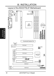
FEATURES The ASUS P2L97 Motherboard T: PS/2 Mouse B: PS/2 Keyboard T: USB Port 1 B: USB Port 2 B: COM 1 T: Parallel B: Serial B: COM 2 Intel 440LX AGPset 3 DIMM Sockets Accelerated Graphics Port 4 PCI Slots Programmable Flash ROM 1 ISA/PCI Share 1 ISA Slot ASUS P2L97 User's Manual 9 II. FEATURES (Motherboard Parts) II.
FEATURES The ASUS P2L97 Motherboard T: PS/2 Mouse B: PS/2 Keyboard T: USB Port 1 B: USB Port 2 B: COM 1 T: Parallel B: Serial B: COM 2 Intel 440LX AGPset 3 DIMM Sockets Accelerated Graphics Port 4 PCI Slots Programmable Flash ROM 1 ISA/PCI Share 1 ISA Slot ASUS P2L97 User's Manual 9 II. FEATURES (Motherboard Parts) II.
P2L97 User Manual
Page 10
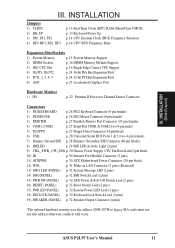
INSTALLATION Layout of the ASUS P2L97 Motherboard PS/2 Top: Mouse Bottom: Keyboard KB_UP Top: USB USB 1 Bottom: USB 2 PWR_FAN CPU_FAN JP1 Pentium II Thermal Sensor Connector COM 1 Parallel Port COM 2 Intel ... Slot 1 ISA Slot 2 BUS FREQ FS0 FS1 FS2 Intel PIIX4 PCIset CHA_FAN BF0 BF2 BF1 BF3 BUS FREQ IR Connector IDE LED Panel Connectors 10 ASUS P2L97 User's Manual DIMM Socket 1 (64/72 bit, 168 pin module) DIMM Socket 2 (64/72 bit, 168 pin module) DIMM Socket 3 (64/72 bit, 168 pin module...
INSTALLATION Layout of the ASUS P2L97 Motherboard PS/2 Top: Mouse Bottom: Keyboard KB_UP Top: USB USB 1 Bottom: USB 2 PWR_FAN CPU_FAN JP1 Pentium II Thermal Sensor Connector COM 1 Parallel Port COM 2 Intel ... Slot 1 ISA Slot 2 BUS FREQ FS0 FS1 FS2 Intel PIIX4 PCIset CHA_FAN BF0 BF2 BF1 BF3 BUS FREQ IR Connector IDE LED Panel Connectors 10 ASUS P2L97 User's Manual DIMM Socket 1 (64/72 bit, 168 pin module) DIMM Socket 2 (64/72 bit, 168 pin module) DIMM Socket 3 (64/72 bit, 168 pin module...
P2L97 User Manual
Page 11
... Output Connector (4 pins) *The onboard hardware monitor uses the address 290H-297H so legacy ISA cards must not use this address otherwise conflicts will occur. ASUS P2L97 User's Manual 11 INSTALLATION (Board Layout) III. III.
... Output Connector (4 pins) *The onboard hardware monitor uses the address 290H-297H so legacy ISA cards must not use this address otherwise conflicts will occur. ASUS P2L97 User's Manual 11 INSTALLATION (Board Layout) III. III.
P2L97 User Manual
Page 12
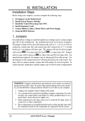
... Jumpers on jumpers with three pins. See motherboard layout for Open (Off). To protect them against damage from the system. 12 ASUS P2L97 User's Manual Use a grounded wrist strap before handling computer components. Hold components by the edges and try not to connect pins 2&3. INSTALLATION Installation... Steps Before using your computer. 1. Use the diagrams in this manual instead of jumpers. Jumpers with two pins will be shown as for Short (On) and for locations of following steps: 1. Install...
... Jumpers on jumpers with three pins. See motherboard layout for Open (Off). To protect them against damage from the system. 12 ASUS P2L97 User's Manual Use a grounded wrist strap before handling computer components. Hold components by the edges and try not to connect pins 2&3. INSTALLATION Installation... Steps Before using your computer. 1. Use the diagrams in this manual instead of jumpers. Jumpers with two pins will be shown as for Short (On) and for locations of following steps: 1. Install...
P2L97 User Manual
Page 13
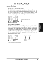
...support. Your computer will not function if you want to Disable because not all computers have the right ATX power supply. INSTALLATION Jumper Settings 1. R P2L97 Keyboard Power (Wake) Up KB_UP 1 2 3 Disable (Default) KB_UP 1 2 3 Enable III. This feature requires an ATX power supply that... or enable the keyboard power up your computer, (4) Hold down during bootup and enter BIOS setup to clear CLRTC P2L97 Clear RTC RAM 2. INSTALLATION (Jumpers) ASUS P2L97 User's Manual 13 R Short small solder points to re-enter user preferences. Real Time Clock (RTC) RAM (CLRTC) The ...
...support. Your computer will not function if you want to Disable because not all computers have the right ATX power supply. INSTALLATION Jumper Settings 1. R P2L97 Keyboard Power (Wake) Up KB_UP 1 2 3 Disable (Default) KB_UP 1 2 3 Enable III. This feature requires an ATX power supply that... or enable the keyboard power up your computer, (4) Hold down during bootup and enter BIOS setup to clear CLRTC P2L97 Clear RTC RAM 2. INSTALLATION (Jumpers) ASUS P2L97 User's Manual 13 R Short small solder points to re-enter user preferences. Real Time Clock (RTC) RAM (CLRTC) The ...
P2L97 User Manual
Page 14
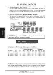
FS2 FS1 FS0 FS2 FS1 FS0 FS2 FS1 FS0 FS2 FS1 FS0 P2L97 CPU Jumpers 1 1 1 1 2 2 2 2 3 3 3 3 60MHz 66MHz 75MHz 83MHz CPU Bus Frequency 123 123 123 123 123 BF3 BF3 BF3 BF3 BF3 BF2 BF2 BF2 BF2 BF2 BF1 ... Frequency. Frequencies above 66MHz exceed the specifications for the Pentium II processor because it sends a VID signal directly to the onboard power controller. 14 ASUS P2L97 User's Manual Intel Pentium II Processor in a slower speed. The BUS Clock multiplied by the Internal speed of your processor is not needed for the onboard Intel...
FS2 FS1 FS0 FS2 FS1 FS0 FS2 FS1 FS0 FS2 FS1 FS0 P2L97 CPU Jumpers 1 1 1 1 2 2 2 2 3 3 3 3 60MHz 66MHz 75MHz 83MHz CPU Bus Frequency 123 123 123 123 123 BF3 BF3 BF3 BF3 BF3 BF2 BF2 BF2 BF2 BF2 BF1 ... Frequency. Frequencies above 66MHz exceed the specifications for the Pentium II processor because it sends a VID signal directly to the onboard power controller. 14 ASUS P2L97 User's Manual Intel Pentium II Processor in a slower speed. The BUS Clock multiplied by the Internal speed of your processor is not needed for the onboard Intel...

P2L97 User Manual
Page 15
...; ○ ○ ○ ○ ○ ○ ○ ○ ○ ○ ○ ○ ○ ○ ○ ○ ○ ○ ○ ○ ○ ○ ○ ○ ○ ASUS P2L97 User's Manual 15
...; ○ ○ ○ ○ ○ ○ ○ ○ ○ ○ ○ ○ ○ ○ ○ ○ ○ ○ ○ ○ ○ ○ ○ ○ ○ ASUS P2L97 User's Manual 15

P2L97 User Manual
Page 16
...; ○ ○ ○ ○ ○ ○ ○ ○ ○ ○ ○ ○ ○ ○ ○ ○ ○ ○ ○ ○ ○ ○ ○ ○ 16 ASUS P2L97 User's Manual
...; ○ ○ ○ ○ ○ ○ ○ ○ ○ ○ ○ ○ ○ ○ ○ ○ ○ ○ ○ ○ ○ ○ ○ ○ 16 ASUS P2L97 User's Manual
P2L97 User Manual
Page 17
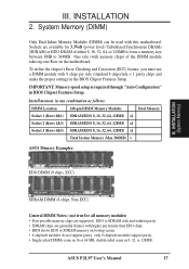
... Correction (ECC) feature, you must use a DIMM module with higher pin density than EDO chips. • BIOS shows EDO or SDRAM memory on the motherboard. ASUS P2L97 User's Manual 17 One side (with this motherboard. III. INSTALLATION (System Memory) SDRAM DIMM (8 chips, Non-ECC) General DIMM Notes: (not true for 3.3Volt (power level..., 128MB x1 Socket 2 (Rows 2&3) SDRAM/EDO 8, 16, 32, 64, 128MB x1 Socket 3 (Rows 4&5) SDRAM/EDO 8, 16, 32, 64, 128MB x1 Total System Memory (Max 384MB) = ASUS Memory Examples: EDO DIMM (9 chips, ECC) III. Install memory in 8, 32, or 128MB.
... Correction (ECC) feature, you must use a DIMM module with higher pin density than EDO chips. • BIOS shows EDO or SDRAM memory on the motherboard. ASUS P2L97 User's Manual 17 One side (with this motherboard. III. INSTALLATION (System Memory) SDRAM DIMM (8 chips, Non-ECC) General DIMM Notes: (not true for 3.3Volt (power level..., 128MB x1 Socket 2 (Rows 2&3) SDRAM/EDO 8, 16, 32, 64, 128MB x1 Socket 3 (Rows 4&5) SDRAM/EDO 8, 16, 32, 64, 128MB x1 Total System Memory (Max 384MB) = ASUS Memory Examples: EDO DIMM (9 chips, ECC) III. Install memory in 8, 32, or 128MB.

P2L97 User Manual
Page 18
Because the number of pins are supported on both sides. DRAM SIMM modules have a higher pin density. 20 Pins 60 Pins 88 Pins Loc P2L97 168 Pin DIMM Memory Sockets The Dual Inline Memory Module (DIMM) memory modules must ask your retailer for the specifications before purchasing. You can identify .... INSTALLATION (System Memory) III. SDRAM DIMM modules have different pint contact on each side and therefore have the same pin contact on this motherboard. 18 ASUS P2L97 User's Manual INSTALLATION DIMM Memory Installation Procedures: Insert the module(s) as shown.
Because the number of pins are supported on both sides. DRAM SIMM modules have a higher pin density. 20 Pins 60 Pins 88 Pins Loc P2L97 168 Pin DIMM Memory Sockets The Dual Inline Memory Module (DIMM) memory modules must ask your retailer for the specifications before purchasing. You can identify .... INSTALLATION (System Memory) III. SDRAM DIMM modules have different pint contact on each side and therefore have the same pin contact on this motherboard. 18 ASUS P2L97 User's Manual INSTALLATION DIMM Memory Installation Procedures: Insert the module(s) as shown.

P2L97 User Manual
Page 19
..., if necessary. The URM supports Pentium II and Celeron processors. Without sufficient circulation, the processor could overheat and damage both the processor and the motherboard. ASUS P2L97 User's Manual 19 WARNING! INSTALLATION CPU Universal Retention Mechanism (URM) Heatsinks The recommended heatsinks (see section on recommended heatsinks for Pentium II processors for more information...
..., if necessary. The URM supports Pentium II and Celeron processors. Without sufficient circulation, the processor could overheat and damage both the processor and the motherboard. ASUS P2L97 User's Manual 19 WARNING! INSTALLATION CPU Universal Retention Mechanism (URM) Heatsinks The recommended heatsinks (see section on recommended heatsinks for Pentium II processors for more information...
P2L97 User Manual
Page 20
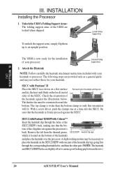
... holes, and then the other pair. (NOTE: The heatsink and SECC2/SEPP holes are slightly offset to ensure good locking grip between the two.) 20 ASUS P2L97 User's Manual With a screw driver, push the clamps one pair of the heatsink against the SECC. INSTALLATION Installing the Processor 1. The following steps are locked when...
... holes, and then the other pair. (NOTE: The heatsink and SECC2/SEPP holes are slightly offset to ensure good locking grip between the two.) 20 ASUS P2L97 User's Manual With a screw driver, push the clamps one pair of the heatsink against the SECC. INSTALLATION Installing the Processor 1. The following steps are locked when...


