
P2B-L User Manual
Page 5
... Disk Utilities 77 IX. NETWORK INTERFACE Features 63 Software Driver Support 63 LED Connectors 64 DOS and Windows 3.1 Setup for DOS/Windows 3.1x Users 83 DOS Formatting Utilities 84 Low-level Formatter (scsifmt 84 Formatter and Partitioner (afdisk 85 ASUS P2B-L/P2B-S/P2B-LS User's Manual 5 CONTENTS PNP and PCI Setup 52 Details of PNP...
... Disk Utilities 77 IX. NETWORK INTERFACE Features 63 Software Driver Support 63 LED Connectors 64 DOS and Windows 3.1 Setup for DOS/Windows 3.1x Users 83 DOS Formatting Utilities 84 Low-level Formatter (scsifmt 84 Formatter and Partitioner (afdisk 85 ASUS P2B-L/P2B-S/P2B-LS User's Manual 5 CONTENTS PNP and PCI Setup 52 Details of PNP...
P2B-L User Manual
Page 8
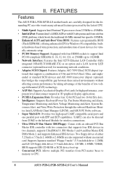
...; Network Interface: Features the Intel 82558 Ethernet LAN Controller (fully integrated 10BASE-T/100BASE-TX) as an option and a LAN Activity LED connector (optional/reserved) for monitoring network conditions. • Adaptec SCSI Chipset: Features Adaptec AIC-7890 Ultra2 SCSI chipset (optional) ...I /O: Provides two high-speed UART compatible serial ports and one parallel port with EPP and ECP capabilities. FEATURES Features The ASUS P2B-L/P2B-S/P2B-LS motherboards are also supported without affecting system performance by the fastest CPU. • Multi-Speed: Supports Intel Pentium®...
...; Network Interface: Features the Intel 82558 Ethernet LAN Controller (fully integrated 10BASE-T/100BASE-TX) as an option and a LAN Activity LED connector (optional/reserved) for monitoring network conditions. • Adaptec SCSI Chipset: Features Adaptec AIC-7890 Ultra2 SCSI chipset (optional) ...I /O: Provides two high-speed UART compatible serial ports and one parallel port with EPP and ECP capabilities. FEATURES Features The ASUS P2B-L/P2B-S/P2B-LS motherboards are also supported without affecting system performance by the fastest CPU. • Multi-Speed: Supports Intel Pentium®...
P2B-L User Manual
Page 10
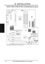
... WOL_CON EXTBATT 2Mbit Flash EEPROM (Programmable BIOS) CHA_FAN PANEL IDELED Combine IR Speaker NOTE: Greyed components are optional at the time of purchase. INSTALLATION ASUS P2B-L/P2B-S/P2B-LS Motherboard Layout DIMM Socket 0 (64/72 bit, 168 pin module) DIMM Socket 1 (64/72 bit, 168 pin module) DIMM Socket...KBPWR COM 1 TRCPU CPU_FAN Intel 440BX AGPset FS2 FS1 BUS Freq. INSTALLATION Board Layout 10 ASUS P2B-L/P2B-S/P2B-LS User's Manual III. III. FS0 68 34 34 68 COM 2 RJ-45 1 FLOPPY LAN Activity LED Connector 35 1 35 1 50-Pin SCSI 1 68-Pin Wide SCSI 68-Pin Ultra2 ...
... WOL_CON EXTBATT 2Mbit Flash EEPROM (Programmable BIOS) CHA_FAN PANEL IDELED Combine IR Speaker NOTE: Greyed components are optional at the time of purchase. INSTALLATION ASUS P2B-L/P2B-S/P2B-LS Motherboard Layout DIMM Socket 0 (64/72 bit, 168 pin module) DIMM Socket 1 (64/72 bit, 168 pin module) DIMM Socket...KBPWR COM 1 TRCPU CPU_FAN Intel 440BX AGPset FS2 FS1 BUS Freq. INSTALLATION Board Layout 10 ASUS P2B-L/P2B-S/P2B-LS User's Manual III. III. FS0 68 34 34 68 COM 2 RJ-45 1 FLOPPY LAN Activity LED Connector 35 1 35 1 50-Pin SCSI 1 68-Pin Wide SCSI 68-Pin Ultra2 ...
P2B-L User Manual
Page 11
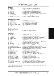
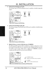
...Enable/Disable) p. 14 Onboard LAN Setting (Enable/Disable) p. 14 Onboard SCSI Setting (Enable/Disable) p. 14 IDE+SCSI LED Activity Light (Separated/Combined) p. 15 CPU Bus Frequency p. 15 CPU Core:Bus Frequency Multiple Expansion Slots/Sockets 1) DIMM Sockets...PANEL) p. 32 Reset Switch Lead (2 pins) 18) KEYLOCK (PANEL) 19) KEYLOCK (PANEL) 20) SPEAKER (PANEL) p. 32 System Power LED (3 pins) p. 32 Keyboard Lock Switch Lead (2 pins) p. 32 Speaker Connector (4 pins) 21) CHASSIS p. 33 Chassis Open Alarm Lead .... III. INSTALLATION Board Layout III. ASUS P2B-L/P2B-S/P2B-LS User's Manual 11
...Enable/Disable) p. 14 Onboard LAN Setting (Enable/Disable) p. 14 Onboard SCSI Setting (Enable/Disable) p. 14 IDE+SCSI LED Activity Light (Separated/Combined) p. 15 CPU Bus Frequency p. 15 CPU Core:Bus Frequency Multiple Expansion Slots/Sockets 1) DIMM Sockets...PANEL) p. 32 Reset Switch Lead (2 pins) 18) KEYLOCK (PANEL) 19) KEYLOCK (PANEL) 20) SPEAKER (PANEL) p. 32 System Power LED (3 pins) p. 32 Keyboard Lock Switch Lead (2 pins) p. 32 Speaker Connector (4 pins) 21) CHASSIS p. 33 Chassis Open Alarm Lead .... III. INSTALLATION Board Layout III. ASUS P2B-L/P2B-S/P2B-LS User's Manual 11
P2B-L User Manual
Page 14
...connected to this jumper. COMBINE (Default) IDELED and SCSILED activity are separate COMBINE IDELED includes SCSILED activity P2B-L/S/LS IDE/SCSI Device Activity LED Selection 14 ASUS P2B-L/P2B-S/P2B-LS User's Manual Onboard SCSI Setting (SCSI_EN) The onboard Adaptec Fast/Wide/Ultra2 SCSI may be enabled... or disabled using this motherboard but only have one LED on your system cabinet, place a jumper on COMBINE ...
...connected to this jumper. COMBINE (Default) IDELED and SCSILED activity are separate COMBINE IDELED includes SCSILED activity P2B-L/S/LS IDE/SCSI Device Activity LED Selection 14 ASUS P2B-L/P2B-S/P2B-LS User's Manual Onboard SCSI Setting (SCSI_EN) The onboard Adaptec Fast/Wide/Ultra2 SCSI may be enabled... or disabled using this motherboard but only have one LED on your system cabinet, place a jumper on COMBINE ...

P2B-L User Manual
Page 28
... Universal Serial Bus (USB) 7. INSTALLATION Connectors P2B-L/S/LS Network Condition LED Connectors 8. After connecting the single end to the board, connect the two plugs on the other end to the floppy drives. (Pin 5 is ... provided floppy disk drive ribbon cable. Universal Serial BUS Ports 1 & 2 (Two 4-pin Female) Two USB ports are available for connecting USB devices. Link LED Connector Activity LED Connector Speed LED Connector R R III. III. This module mounts to Pin 1 Floppy Drive Connector Pin 1 P2B-L/S/LS Floppy Disk Drive Connector 28 ASUS P2B-L/P2B-S/P2B-LS User's Manual
... Universal Serial Bus (USB) 7. INSTALLATION Connectors P2B-L/S/LS Network Condition LED Connectors 8. After connecting the single end to the board, connect the two plugs on the other end to the floppy drives. (Pin 5 is ... provided floppy disk drive ribbon cable. Universal Serial BUS Ports 1 & 2 (Two 4-pin Female) Two USB ports are available for connecting USB devices. Link LED Connector Activity LED Connector Speed LED Connector R R III. III. This module mounts to Pin 1 Floppy Drive Connector Pin 1 P2B-L/S/LS Floppy Disk Drive Connector 28 ASUS P2B-L/P2B-S/P2B-LS User's Manual

P2B-L User Manual
Page 29
...another ribbon cable on a SCSI drive and select the boot disk through BIOS Features Setup. INSTALLATION Connectors R P2B-L/S/LS IDE Connectors 10. TIP: If the case-mounted LED does not light, try reversing the 2-pin plug. You may configure two hard disks to be both the...pin 20 plugged). III. If the COMBINE jumper is removed to your hard disk for the jumper settings. IDELED SCSILED P2B-L/S/LS IDE/SCSI Device Activity LED R ASUS P2B-L/P2B-S/P2B-LS User's Manual 29 Primary / Secondary IDE connectors (Two 40-1pin IDE) These connectors support the provided IDE hard...
...another ribbon cable on a SCSI drive and select the boot disk through BIOS Features Setup. INSTALLATION Connectors R P2B-L/S/LS IDE Connectors 10. TIP: If the case-mounted LED does not light, try reversing the 2-pin plug. You may configure two hard disks to be both the...pin 20 plugged). III. If the COMBINE jumper is removed to your hard disk for the jumper settings. IDELED SCSILED P2B-L/S/LS IDE/SCSI Device Activity LED R ASUS P2B-L/P2B-S/P2B-LS User's Manual 29 Primary / Secondary IDE connectors (Two 40-1pin IDE) These connectors support the provided IDE hard...
P2B-L User Manual
Page 32
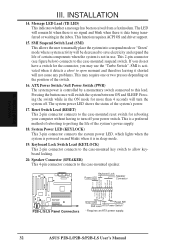
... require one or two presses depending on and blinks when it shorted will switch the system between ON and SLEEP. Message LED Lead (TB LED) This indicates whether a message has been received from a fax/modem. Keyboard Lock Switch Lead (KEYLOCK) This 2-pin .... 19. Keyboard Lock Speaker Power LED Connector +5 V PLED KEYLOCK Ground +5V Ground Ground SPKR +5 V TB_LED ExtSMI# Ground PWR_SW +3VSB ResetCon Ground P2B-L/S/LS Panel Connectors Turbo LED Reset SW SMI Lead ATX Power Switch* * Requires an ATX power supply. 32 ASUS P2B-L/P2B-S/P2B-LS User's Manual INSTALLATION Connectors III...
... require one or two presses depending on and blinks when it shorted will switch the system between ON and SLEEP. Message LED Lead (TB LED) This indicates whether a message has been received from a fax/modem. Keyboard Lock Switch Lead (KEYLOCK) This 2-pin .... 19. Keyboard Lock Speaker Power LED Connector +5 V PLED KEYLOCK Ground +5V Ground Ground SPKR +5 V TB_LED ExtSMI# Ground PWR_SW +3VSB ResetCon Ground P2B-L/S/LS Panel Connectors Turbo LED Reset SW SMI Lead ATX Power Switch* * Requires an ATX power supply. 32 ASUS P2B-L/P2B-S/P2B-LS User's Manual INSTALLATION Connectors III...

P2B-L User Manual
Page 35
...For ATX power supplies, you need to switch on the power supply as well as press the ATX power switch on the chain) c. ASUS P2B-L/P2B-S/P2B-LS User's Manual 35 After all switches are running, additional messages will light. Connect the power cord into the power supply located on the... front panel of your retailer for assistance. 7. Your system power. The monitor LED may light up after Windows shuts down to your operating system. During power-on tests. If you do not see anything within 30 seconds...
...For ATX power supplies, you need to switch on the power supply as well as press the ATX power switch on the chain) c. ASUS P2B-L/P2B-S/P2B-LS User's Manual 35 After all switches are running, additional messages will light. Connect the power cord into the power supply located on the... front panel of your retailer for assistance. 7. Your system power. The monitor LED may light up after Windows shuts down to your operating system. During power-on tests. If you do not see anything within 30 seconds...

P2B-L User Manual
Page 64
... is off , the computer is not sending or receiving network data. Activity Indicator: This connects to an LED to the RJ45 connector. Connect a single network cable to monitor network activity. For 10BASE-T, use category 3,...faulty or the driver configuration may be faulty. HUB 3 OTD+ 3 IRD+ 6 OTD- 6 IRD- The LED lights to indicate a successful network connection, and remains steady if the connection is made to a 100BASE-TX hub (not a ...Output Transmit Data Input Receive Data + Input Receive Data (Reserved) HUB RJ45 Connector 12345678 64 ASUS P2B-L/P2B-S/P2B-LS User's Manual
... is off , the computer is not sending or receiving network data. Activity Indicator: This connects to an LED to the RJ45 connector. Connect a single network cable to monitor network activity. For 10BASE-T, use category 3,...faulty or the driver configuration may be faulty. HUB 3 OTD+ 3 IRD+ 6 OTD- 6 IRD- The LED lights to indicate a successful network connection, and remains steady if the connection is made to a 100BASE-TX hub (not a ...Output Transmit Data Input Receive Data + Input Receive Data (Reserved) HUB RJ45 Connector 12345678 64 ASUS P2B-L/P2B-S/P2B-LS User's Manual

P2B-L User Manual
Page 71
...interface is not sending or receiving network data. or you 're directly connecting two computers (no hub), use a crossover cable. ASUS P2B-L/P2B-S/P2B-LS User's Manual 71 NETWORK INTERFACE Troubleshooting If the interface can degrade performance, cause data loss, or result in lost connections. ...adapter. VII. The optional network condition connector module has three diagnostic LEDs . The table below describes the LEDs. These lights help indicate if there's a problem with the amount of network traffic. LED Indication LNK On Off Meaning The interface and hub have the same ...
...interface is not sending or receiving network data. or you 're directly connecting two computers (no hub), use a crossover cable. ASUS P2B-L/P2B-S/P2B-LS User's Manual 71 NETWORK INTERFACE Troubleshooting If the interface can degrade performance, cause data loss, or result in lost connections. ...adapter. VII. The optional network condition connector module has three diagnostic LEDs . The table below describes the LEDs. These lights help indicate if there's a problem with the amount of network traffic. LED Indication LNK On Off Meaning The interface and hub have the same ...

P2B-L User Manual
Page 72
... sure you have the correct type of cable between the network interface or adapter and the hub. 100 BASE-TX requires two pairs. The ACT LED doesn't light. • Make sure you are loaded. • Change the PCI BIOS interrupt settings. Try another port on the hub. •...file. • Make sure the duplex mode setting on the network interface or adapter matches the setting on the ASUS Configuration and Drivers disk. See the next page for TX wiring. 72 ASUS P2B-L/P2B-S/P2B-LS User's Manual Some hubs require a crossover cable while others require a straight-through cable. For DOS or...
... sure you have the correct type of cable between the network interface or adapter and the hub. 100 BASE-TX requires two pairs. The ACT LED doesn't light. • Make sure you are loaded. • Change the PCI BIOS interrupt settings. Try another port on the hub. •...file. • Make sure the duplex mode setting on the network interface or adapter matches the setting on the ASUS Configuration and Drivers disk. See the next page for TX wiring. 72 ASUS P2B-L/P2B-S/P2B-LS User's Manual Some hubs require a crossover cable while others require a straight-through cable. For DOS or...

P2B-L User Manual
Page 73
... network cable is current. • Make sure the other network interface or adapter supports shared interrupts. OS/2* doesn't. NETWORK Problems/Solutions VII. ASUS P2B-L/P2B-S/P2B-LS User's Manual 73 The interface stopped working . • Make sure the WOL cable is attached and power is applied to the network ...interface or adapter. VII. Link LED does not light when power is connected. • Make sure WOL cable is attached and power is applied to the motherboard's network ...
... network cable is current. • Make sure the other network interface or adapter supports shared interrupts. OS/2* doesn't. NETWORK Problems/Solutions VII. ASUS P2B-L/P2B-S/P2B-LS User's Manual 73 The interface stopped working . • Make sure the WOL cable is attached and power is applied to the network ...interface or adapter. VII. Link LED does not light when power is connected. • Make sure WOL cable is attached and power is applied to the motherboard's network ...

P2B-L User Manual
Page 76
... the access method. Interrupt (IRQ) Signal suspending a program temporarily and transfers control to communicate with LAN cards. This standard is required. LED Light emitting diode Mbps Megabits per second 76 ASUS P2B-L/P2B-S/P2B-LS User's Manual Boot ROM Read-only memory chip that enables the network operating system to the operating system when input...
... the access method. Interrupt (IRQ) Signal suspending a program temporarily and transfers control to communicate with LAN cards. This standard is required. LED Light emitting diode Mbps Megabits per second 76 ASUS P2B-L/P2B-S/P2B-LS User's Manual Boot ROM Read-only memory chip that enables the network operating system to the operating system when input...


