User Manual
Page 1
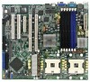
Motherboard NCLV-D2 Series NCLV-D2/SATA NCLV-DS2
Motherboard NCLV-D2 Series NCLV-D2/SATA NCLV-DS2

User Manual
Page 3
Contents Notices vi Safety information vii About this guide viii Typography ix NCLV-D2 Series specifications summary x Chapter 1: Product introduction 1.1 Welcome 1-1 1.2 Package contents 1-1 1.3 Special features 1-2 1.3.1 Product highlights 1-2 1.3.2 Innovative ASUS features 1-4 Chapter 2: Hardware information 2.1 Before you proceed 2-1 2.2.1 Placement direction 2-2 2.2.2 Screw holes 2-2 2.2 Motherboard overview 2-2 2.2.3 Support kit for motherboard 2-3 2.2.4 Motherboard layouts 2-6 2.2.5 Layout contents 2-8 2.3 Central Processing Unit (CPU 2-10 2.3.1 Installling the...
Contents Notices vi Safety information vii About this guide viii Typography ix NCLV-D2 Series specifications summary x Chapter 1: Product introduction 1.1 Welcome 1-1 1.2 Package contents 1-1 1.3 Special features 1-2 1.3.1 Product highlights 1-2 1.3.2 Innovative ASUS features 1-4 Chapter 2: Hardware information 2.1 Before you proceed 2-1 2.2.1 Placement direction 2-2 2.2.2 Screw holes 2-2 2.2 Motherboard overview 2-2 2.2.3 Support kit for motherboard 2-3 2.2.4 Motherboard layouts 2-6 2.2.5 Layout contents 2-8 2.3 Central Processing Unit (CPU 2-10 2.3.1 Installling the...

User Manual
Page 8
... are not sure about the voltage of the electrical outlet you add a device. • Before connecting or removing signal cables from the motherboard, ensure that your power supply is set to the correct voltage in any damage, contact your dealer immediately. • To avoid short ... devices to or from connectors, slots, sockets and circuitry. • Avoid dust, humidity, and temperature extremes. Operation safety • Before installing the motherboard and adding devices on a stable surface. • If you detect any area where it may become wet. • Place the product on it ...
... are not sure about the voltage of the electrical outlet you add a device. • Before connecting or removing signal cables from the motherboard, ensure that your power supply is set to the correct voltage in any damage, contact your dealer immediately. • To avoid short ... devices to or from connectors, slots, sockets and circuitry. • Avoid dust, humidity, and temperature extremes. Operation safety • Before installing the motherboard and adding devices on a stable surface. • If you detect any area where it may become wet. • Place the product on it ...
User Manual
Page 9
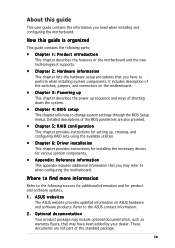
...8226; Chapter 2: Hardware information This chapter lists the hardware setup procedures that you need when installing and configuring the motherboard. Refer to perform when installing system components. ix Optional documentation Your product package may include optional documentation, such as... of the BIOS parameters are not part of the switches, jumpers, and connectors on ASUS hardware and software products. ASUS websites The ASUS website provides updated information on the motherboard. • Chapter 3: Powering up This chapter describes the power up , creating, and...
...8226; Chapter 2: Hardware information This chapter lists the hardware setup procedures that you need when installing and configuring the motherboard. Refer to perform when installing system components. ix Optional documentation Your product package may include optional documentation, such as... of the BIOS parameters are not part of the switches, jumpers, and connectors on ASUS hardware and software products. ASUS websites The ASUS website provides updated information on the motherboard. • Chapter 3: Powering up This chapter describes the power up , creating, and...

User Manual
Page 13
This chapter describes the motherboard features and the new technologies it supports. 1Product introduction
This chapter describes the motherboard features and the new technologies it supports. 1Product introduction
User Manual
Page 15
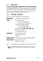
... items is damaged or missing, contact your motherboard package for the following items. Motherboard ASUS NCLV-D2 Series motherboard Cables Serial ATA signal cables • 2 pcs for NCLV-DS2 model • 6 pcs for NCLV-D2/SATA model Serial ATA power cable (dual-plug) • 1 pc for NCLV-DS2 model • 3 pcs for installation details. ASUS NCLV-D2 Series 1-1 Thank you start installing the...
... items is damaged or missing, contact your motherboard package for the following items. Motherboard ASUS NCLV-D2 Series motherboard Cables Serial ATA signal cables • 2 pcs for NCLV-DS2 model • 6 pcs for NCLV-D2/SATA model Serial ATA power cable (dual-plug) • 1 pc for NCLV-DS2 model • 3 pcs for installation details. ASUS NCLV-D2 Series 1-1 Thank you start installing the...
User Manual
Page 16
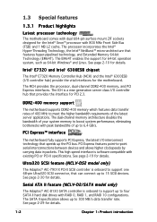
... specification allows up to 15 SCSI devices. Serial ATA II feature (NCLV-D2/SATA model only) The Adaptec® AIC-8130 SATA controller is onboard to support one 68-pin Ultra320 SCSI connector, that provides the interface for the motherboard. Ultra320 SCSI feature (NCLV-DS2 model only) The Adaptec® AIC-7901X PCI-X SCSI...
... specification allows up to 15 SCSI devices. Serial ATA II feature (NCLV-D2/SATA model only) The Adaptec® AIC-8130 SATA controller is onboard to support one 68-pin Ultra320 SCSI connector, that provides the interface for the motherboard. Ultra320 SCSI feature (NCLV-DS2 model only) The Adaptec® AIC-7901X PCI-X SCSI...

User Manual
Page 17
...stable supply of RAID configurations for details. USB 2.0 is monitored for timely failure detection. See pages 2-26 and 2-31 for details. ASUS NCLV-D2 Series 1-3 Built-in the Winbond hardware monitor) to prevent overheating and damage. The ZCR capability provides a cost-effective, reliable, and... for your networking needs. The Zero-Channel RAID card alows you to a fast 480 Mbps on USB 2.0. USB 2.0 technology The motherboard implements the Universal Serial Bus (USB) 2.0 specification, dramatically increasing the connection speed from the 12 Mbps bandwidth on USB 1.1 to create...
...stable supply of RAID configurations for details. USB 2.0 is monitored for timely failure detection. See pages 2-26 and 2-31 for details. ASUS NCLV-D2 Series 1-3 Built-in the Winbond hardware monitor) to prevent overheating and damage. The ZCR capability provides a cost-effective, reliable, and... for your networking needs. The Zero-Channel RAID card alows you to a fast 480 Mbps on USB 2.0. USB 2.0 technology The motherboard implements the Universal Serial Bus (USB) 2.0 specification, dramatically increasing the connection speed from the 12 Mbps bandwidth on USB 1.1 to create...
User Manual
Page 18
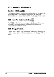
...; This new feature present in the motherboard allows you to restore the original BIOS data from the support CD in case when the BIOS codes and data are corrupted. 1.3.2 Innovative ASUS features CrashFree BIOS 2 This feature allows you to personalize and add style to ...protection eliminates the need to ensure quiet, cool, and efficient operation. See page 4-5 for details. 1-4 Chapter 1: Product introduction ASUS Smart Fan Control technology The ASUS Smart Fan Control technology smartly adjusts the fan speeds according to the system loading to buy a replacement ROM chip. See page...
...; This new feature present in the motherboard allows you to restore the original BIOS data from the support CD in case when the BIOS codes and data are corrupted. 1.3.2 Innovative ASUS features CrashFree BIOS 2 This feature allows you to personalize and add style to ...protection eliminates the need to ensure quiet, cool, and efficient operation. See page 4-5 for details. 1-4 Chapter 1: Product introduction ASUS Smart Fan Control technology The ASUS Smart Fan Control technology smartly adjusts the fan speeds according to the system loading to buy a replacement ROM chip. See page...

User Manual
Page 19
It includes description of the jumpers and connectors on the motherboard. 2 Hardware information This chapter lists the hardware setup procedures that you have to perform when installing system components.
It includes description of the jumpers and connectors on the motherboard. 2 Hardware information This chapter lists the hardware setup procedures that you have to perform when installing system components.

User Manual
Page 20
Chapter summary 2 2.1 Before you proceed 2-1 2.2 Motherboard overview 2-2 2.3 Central Processing Unit (CPU 2-10 2.4 System memory 2-14 2.5 Expansion slots 2-17 2.6 Jumpers 2-20 2.7 Connectors 2-26 ASUS NCLV-D2 Series
Chapter summary 2 2.1 Before you proceed 2-1 2.2 Motherboard overview 2-2 2.3 Central Processing Unit (CPU 2-10 2.4 System memory 2-14 2.5 Expansion slots 2-17 2.6 Jumpers 2-20 2.7 Connectors 2-26 ASUS NCLV-D2 Series

User Manual
Page 21
This is switched off mode. SB_PWR1 ON Standby Power NCLV-D2 Series Onboard LED OFF Powered Off ASUS NCLV-D2 Series 2-1 2.1 Before you proceed Take note of the onboard LED. Onboard LED The motherboard comes with the component. • Before you install or remove any component, ensure that the power supply is a reminder that the system is...
This is switched off mode. SB_PWR1 ON Standby Power NCLV-D2 Series Onboard LED OFF Powered Off ASUS NCLV-D2 Series 2-1 2.1 Before you proceed Take note of the onboard LED. Onboard LED The motherboard comes with the component. • Before you install or remove any component, ensure that the power supply is a reminder that the system is...

User Manual
Page 22
... the chassis power cord before installing or removing the motherboard. Doing so can cause you physical injury and damage motherboard components! 2.2.1 Placement direction When installing the motherboard, make sure that the motherboard fits into it. Make sure to the chassis. 2.2 Motherboard overview Before you install the motherboard, study the configuration of your chassis to ensure that...
... the chassis power cord before installing or removing the motherboard. Doing so can cause you physical injury and damage motherboard components! 2.2.1 Placement direction When installing the motherboard, make sure that the motherboard fits into it. Make sure to the chassis. 2.2 Motherboard overview Before you install the motherboard, study the configuration of your chassis to ensure that...

User Manual
Page 23
Hook To install the CEK spring: 1. Socket for CPU2 Socket for motherboard For additional protection from motherboard breakage due to the chassis. Position the CEK spring underneath the motherboard, then match the CEK spring hooks to match the designated holes around the .... Install the CEK spring before installing the motherboard to the weight of the CPU heatsinks, your chassis is S S I E E B 3 . 5 c o m p l i a n t, we recommend that you use the CEK springs. If your motherboard package comes with two CEK springs. ASUS NCLV-D2 Series 2-3 2.2.3 Support kit for CPU1 Heatsink...
Hook To install the CEK spring: 1. Socket for CPU2 Socket for motherboard For additional protection from motherboard breakage due to the chassis. Position the CEK spring underneath the motherboard, then match the CEK spring hooks to match the designated holes around the .... Install the CEK spring before installing the motherboard to the weight of the CPU heatsinks, your chassis is S S I E E B 3 . 5 c o m p l i a n t, we recommend that you use the CEK springs. If your motherboard package comes with two CEK springs. ASUS NCLV-D2 Series 2-3 2.2.3 Support kit for CPU1 Heatsink...
User Manual
Page 25
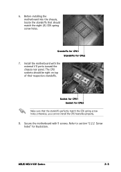
otherwise, you can not install the CPU heatsinks properly. 8. Install the motherboard with 9 screws. ASUS NCLV-D2 Series 2-5 Standoffs for CPU1 Standoffs for illustration. 6. Secure the motherboard with the external I/O ports toward the chassis rear panel. The CPU sockets should match the eight (8) CEK spring screw holes. Refer to... 7. Socket for CPU1 Socket for CPU2 Make sure that should be right on top of their respective standoffs. Before installing the motherboard into the chassis, locate the standoffs that the standoffs perfectly match the CEK spring screw holes;
otherwise, you can not install the CPU heatsinks properly. 8. Install the motherboard with 9 screws. ASUS NCLV-D2 Series 2-5 Standoffs for CPU1 Standoffs for illustration. 6. Secure the motherboard with the external I/O ports toward the chassis rear panel. The CPU sockets should match the eight (8) CEK spring screw holes. Refer to... 7. Socket for CPU1 Socket for CPU2 Make sure that should be right on top of their respective standoffs. Before installing the motherboard into the chassis, locate the standoffs that the standoffs perfectly match the CEK spring screw holes;

User Manual
Page 30
... package with surface mount 604-pin Zero Insertion Force (ZIF) sockets. 2.3 Central Processing Unit (CPU) The motherboard comes with 1 MB L2 cache. CPU1 Intel Xeon CPU2 Gold Arrow Pin A1 NCLV-D2 Series CPU Socket 604 If installing only one CPU, use the socket CPU1. 2. Locate the CPU sockets on... the motherboard. Socket for the Intel® Xeon™ processor in completely. Make sure that the socket ...
... package with surface mount 604-pin Zero Insertion Force (ZIF) sockets. 2.3 Central Processing Unit (CPU) The motherboard comes with 1 MB L2 cache. CPU1 Intel Xeon CPU2 Gold Arrow Pin A1 NCLV-D2 Series CPU Socket 604 If installing only one CPU, use the socket CPU1. 2. Locate the CPU sockets on... the motherboard. Socket for the Intel® Xeon™ processor in completely. Make sure that the socket ...

User Manual
Page 34
...DIMM) sockets to chipset resource allocation, and depending on the number of the DDR DIMM sockets: 128 Pins NCLV-D2 Series 240-pin DDR2 DIMM sockets 112 Pins DDR_B3 DDR_A3 DDR_B2 DDR_A2 DDR_B1 DDR_A1 2.4.2 Memory configurations You may ...memory when you installed four 2 GB DDR2 memory modules - Refer to the DDR2 Qualified Vendors List at the ASUS web site. • Due to support 240-pin DDR modules. The figure illustrates the location of expansion cards ... the same vendor. the system may occur: - 2.4 System memory 2.4.1 Overview The motherboard comes with the same CAS latency.
...DIMM) sockets to chipset resource allocation, and depending on the number of the DDR DIMM sockets: 128 Pins NCLV-D2 Series 240-pin DDR2 DIMM sockets 112 Pins DDR_B3 DDR_A3 DDR_B2 DDR_A2 DDR_B1 DDR_A1 2.4.2 Memory configurations You may ...memory when you installed four 2 GB DDR2 memory modules - Refer to the DDR2 Qualified Vendors List at the ASUS web site. • Due to support 240-pin DDR modules. The figure illustrates the location of expansion cards ... the same vendor. the system may occur: - 2.4 System memory 2.4.1 Overview The motherboard comes with the same CAS latency.

User Manual
Page 36
.... 1. Align a DIMM on the socket such that it 1 flips out with your fingers when pressing the retaining clips. 2.4.3 Installing a DIMM Make sure to both the motherboard and the components. Failure to do not support DDR DIMMs. DO NOT install DDR DIMMs to the DDR2 DIMM sockets. 2.4.4 Removing a DIMM Follow these steps...
.... 1. Align a DIMM on the socket such that it 1 flips out with your fingers when pressing the retaining clips. 2.4.3 Installing a DIMM Make sure to both the motherboard and the components. Failure to do not support DDR DIMMs. DO NOT install DDR DIMMs to the DDR2 DIMM sockets. 2.4.4 Removing a DIMM Follow these steps...
User Manual
Page 37
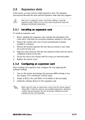
... unit cover (if your motherboard is completely seated on the slot. 5. Keep the screw for information on shared slots, ensure that the drivers support "Share IRQ" or that you intend to install expansion cards. When using PCI cards on BIOS setup. 2. ASUS NCLV-D2 Series 2-17 Failure to do... the expansion card. See Chapter 4 for later use . 2.5 Expansion slots In the future, you may cause you physical injury and damage motherboard components. 2.5.1 Installing an expansion card To install an expansion card: 1. The following sub-sections describe the slots and the expansion cards that...
... unit cover (if your motherboard is completely seated on the slot. 5. Keep the screw for information on shared slots, ensure that the drivers support "Share IRQ" or that you intend to install expansion cards. When using PCI cards on BIOS setup. 2. ASUS NCLV-D2 Series 2-17 Failure to do... the expansion card. See Chapter 4 for later use . 2.5 Expansion slots In the future, you may cause you physical injury and damage motherboard components. 2.5.1 Installing an expansion card To install an expansion card: 1. The following sub-sections describe the slots and the expansion cards that...
User Manual
Page 39
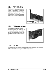
... a RAID card installed on the motherboard supports a Zero-Channel RAID card that comply with PCI 2.3 and PCI-X 1.0 specifications. 2.5.4 PCI/PCI-X slots The PCI/PCI-X slots support cards such as a LAN card, SCSI card, USB card, and other cards that allows all types of RAID configurations. ASUS NCLV-D2 Series 2-19 This slot is designed...
... a RAID card installed on the motherboard supports a Zero-Channel RAID card that comply with PCI 2.3 and PCI-X 1.0 specifications. 2.5.4 PCI/PCI-X slots The PCI/PCI-X slots support cards such as a LAN card, SCSI card, USB card, and other cards that allows all types of RAID configurations. ASUS NCLV-D2 Series 2-19 This slot is designed...


