User Manual
Page 15
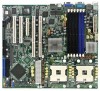
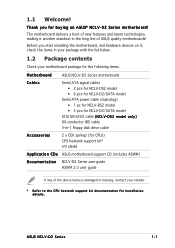
... below. 1.2 Package contents Check your retailer. * Refer to the CPU heatsink support kit documentation for buying an ASUS® NCLV-D2 Series motherboard! ASUS NCLV-D2 Series 1-1 Before you for installation details. The motherboard delivers a host of new features and latest technologies, making it...motherboard package for the following items. Motherboard ASUS NCLV-D2 Series motherboard Cables Serial ATA signal cables • 2 pcs for NCLV-DS2 model • 6 pcs for NCLV-D2/SATA model Serial ATA power cable (dual-plug) • 1 pc for NCLV-DS2 model • 3 pcs for ...
... below. 1.2 Package contents Check your retailer. * Refer to the CPU heatsink support kit documentation for buying an ASUS® NCLV-D2 Series motherboard! ASUS NCLV-D2 Series 1-1 Before you for installation details. The motherboard delivers a host of new features and latest technologies, making it...motherboard package for the following items. Motherboard ASUS NCLV-D2 Series motherboard Cables Serial ATA signal cables • 2 pcs for NCLV-DS2 model • 6 pcs for NCLV-D2/SATA model Serial ATA power cable (dual-plug) • 1 pc for NCLV-DS2 model • 3 pcs for ...

User Manual
Page 17
See pages 2-28 and 5-4 for details. The ZCR capability provides a cost-effective, reliable, and high-performance RAID solution. ASUS NCLV-D2 Series 1-3 Built-in the Winbond hardware monitor) to prevent overheating and damage. Gigabit LAN solution The motherboard comes with a 64-bit PCI-X slot for an ...
See pages 2-28 and 5-4 for details. The ZCR capability provides a cost-effective, reliable, and high-performance RAID solution. ASUS NCLV-D2 Series 1-3 Built-in the Winbond hardware monitor) to prevent overheating and damage. Gigabit LAN solution The motherboard comes with a 64-bit PCI-X slot for an ...

User Manual
Page 20
Chapter summary 2 2.1 Before you proceed 2-1 2.2 Motherboard overview 2-2 2.3 Central Processing Unit (CPU 2-10 2.4 System memory 2-14 2.5 Expansion slots 2-17 2.6 Jumpers 2-20 2.7 Connectors 2-26 ASUS NCLV-D2 Series
Chapter summary 2 2.1 Before you proceed 2-1 2.2 Motherboard overview 2-2 2.3 Central Processing Unit (CPU 2-10 2.4 System memory 2-14 2.5 Expansion slots 2-17 2.6 Jumpers 2-20 2.7 Connectors 2-26 ASUS NCLV-D2 Series

User Manual
Page 21
... touching any component. • Use a grounded wrist strap or touch a safely grounded object or to the motherboard, peripherals, and/or components. SB_PWR1 ON Standby Power NCLV-D2 Series Onboard LED OFF Powered Off ASUS NCLV-D2 Series 2-1
... touching any component. • Use a grounded wrist strap or touch a safely grounded object or to the motherboard, peripherals, and/or components. SB_PWR1 ON Standby Power NCLV-D2 Series Onboard LED OFF Powered Off ASUS NCLV-D2 Series 2-1

User Manual
Page 23
Install the CEK spring before installing the motherboard to the CPU1 heatsink holes. If your motherboard package comes with two CEK springs. ASUS NCLV-D2 Series 2-3 Locate the CPU heatsink holes on the motherboard. Socket for CPU2 Socket for motherboard For additional protection from motherboard breakage due to match the ...
Install the CEK spring before installing the motherboard to the CPU1 heatsink holes. If your motherboard package comes with two CEK springs. ASUS NCLV-D2 Series 2-3 Locate the CPU heatsink holes on the motherboard. Socket for CPU2 Socket for motherboard For additional protection from motherboard breakage due to match the ...
User Manual
Page 25
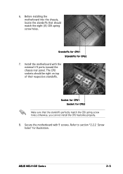
... motherboard with the external I/O ports toward the chassis rear panel. Standoffs for CPU1 Standoffs for CPU2 7. otherwise, you can not install the CPU heatsinks properly. 8. ASUS NCLV-D2 Series 2-5 Before installing the motherboard into the chassis, locate the standoffs that the standoffs perfectly match the CEK spring screw holes;
... motherboard with the external I/O ports toward the chassis rear panel. Standoffs for CPU1 Standoffs for CPU2 7. otherwise, you can not install the CPU heatsinks properly. 8. ASUS NCLV-D2 Series 2-5 Before installing the motherboard into the chassis, locate the standoffs that the standoffs perfectly match the CEK spring screw holes;

User Manual
Page 31
... with the CPU package. 7. Apply the thermal interface material (thermal grease) to install a second CPU. The CPU fits only in place. Marked corner (gold arrow) ASUS NCLV-D2 Series 2-11 Repeat steps 1 to 6 if you wish to the top of the CPU. 3. Position the CPU above the socket as shown. 4.
... with the CPU package. 7. Apply the thermal interface material (thermal grease) to install a second CPU. The CPU fits only in place. Marked corner (gold arrow) ASUS NCLV-D2 Series 2-11 Repeat steps 1 to 6 if you wish to the top of the CPU. 3. Position the CPU above the socket as shown. 4.
User Manual
Page 33
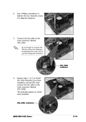
Repeat steps 1 to 3 to install the other heatsink if you fail to plug this connector. 4. Hardware monitoring errors may occur if you have installed a second CPU, then connect the fan cable to connect the CPU fan connector! The heatsinks appear as shown when installed. CPU_FAN2 connector ASUS NCLV-D2 Series CPU_FAN1 connector 2-13 Connect the fan cable to tighten the four heatsink screws in a diagonal sequence. 3. 2. Use a Phillips screwdriver to the 4-pin connector labeled CPU_FAN1. Do not forget to the 4-pin connector labeled CPU_FAN2.
Repeat steps 1 to 3 to install the other heatsink if you fail to plug this connector. 4. Hardware monitoring errors may occur if you have installed a second CPU, then connect the fan cable to connect the CPU fan connector! The heatsinks appear as shown when installed. CPU_FAN2 connector ASUS NCLV-D2 Series CPU_FAN1 connector 2-13 Connect the fan cable to tighten the four heatsink screws in a diagonal sequence. 3. 2. Use a Phillips screwdriver to the 4-pin connector labeled CPU_FAN1. Do not forget to the 4-pin connector labeled CPU_FAN2.

User Manual
Page 35
Mode DDR_B3 DDR_A3 DDR_B2 DDR_A2 DDR-B1 DDR_A1 (blue) (blue) (black) (black) (black) (black) Single-channel Dual-channel Populated with DIMM Single and dual rank mixing MCH Dual Rank DIMM B3 Dual Rank DIMM A3 Dual Rank DIMM B2 Dual Rank DIMM A2 MCH Dual Rank DIMM B3 Dual Rank DIMM A3 Single Rank DIMM B2 Single Rank DIMM A2 Single Rank DIMM B1 Single Rank DIMM A1 ASUS NCLV-D2 Series 2-15
Mode DDR_B3 DDR_A3 DDR_B2 DDR_A2 DDR-B1 DDR_A1 (blue) (blue) (black) (black) (black) (black) Single-channel Dual-channel Populated with DIMM Single and dual rank mixing MCH Dual Rank DIMM B3 Dual Rank DIMM A3 Dual Rank DIMM B2 Dual Rank DIMM A2 MCH Dual Rank DIMM B3 Dual Rank DIMM A3 Single Rank DIMM B2 Single Rank DIMM A2 Single Rank DIMM B1 Single Rank DIMM A1 ASUS NCLV-D2 Series 2-15
User Manual
Page 37
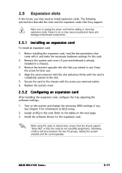
.... Replace the system cover. 2.5.2 Configuring an expansion card After installing the expansion card, configure the it and make the necessary hardware settings for later use . ASUS NCLV-D2 Series 2-17 Before installing the expansion card, read the documentation that they support. When using PCI cards on the next page. 3. Otherwise, conflicts will arise...
.... Replace the system cover. 2.5.2 Configuring an expansion card After installing the expansion card, configure the it and make the necessary hardware settings for later use . ASUS NCLV-D2 Series 2-17 Before installing the expansion card, read the documentation that they support. When using PCI cards on the next page. 3. Otherwise, conflicts will arise...
User Manual
Page 39
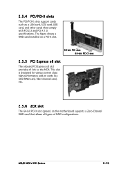
ASUS NCLV-D2 Series 2-19 The figure shows a RAID card installed on the motherboard supports a Zero-Channel RAID card that comply with PCI 2.3 and PCI-X 1.0 specifications. 2.5.4 PCI/PCI-X ...
ASUS NCLV-D2 Series 2-19 The figure shows a RAID card installed on the motherboard supports a Zero-Channel RAID card that comply with PCI 2.3 and PCI-X 1.0 specifications. 2.5.4 PCI/PCI-X ...
User Manual
Page 41
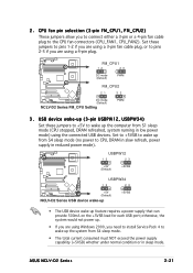
... Windows 2000, you are using a 4-pin plug. CPU fan pin selection (3-pin FM_CPU1, FM_CPU2) These jumpers allow you are using the connected USB devices. ASUS NCLV-D2 Series 2-21 Set these jumpers to +5V to wake up (3-pin USBPW12, USBPW34) Set these jumpers to pins 1-2 if you are using a 3-pin fan...plug to CPU, DRAM in slow refresh, power supply in sleep mode. USBPW12 12 23 +5V (Default) +5VSB USBPW34 12 23 +5V (Default) NCLV-D2 Series USB device wake-up +5VSB • The USB device wake-up from S4 sleep mode. • The total current consumed must NOT exceed the...
... Windows 2000, you are using a 4-pin plug. CPU fan pin selection (3-pin FM_CPU1, FM_CPU2) These jumpers allow you are using the connected USB devices. ASUS NCLV-D2 Series 2-21 Set these jumpers to +5V to wake up (3-pin USBPW12, USBPW34) Set these jumpers to pins 1-2 if you are using a 3-pin fan...plug to CPU, DRAM in slow refresh, power supply in sleep mode. USBPW12 12 23 +5V (Default) +5VSB USBPW34 12 23 +5V (Default) NCLV-D2 Series USB device wake-up +5VSB • The USB device wake-up from S4 sleep mode. • The total current consumed must NOT exceed the...

User Manual
Page 43
... setting (3-pin LAN2_EN1) These jumpers allow you to enable or disable the onboard Broadcom® BCM5705E Gigabit LAN2 controller. LAN_EN2 2 1 Enable (Default) 3 2 Disable NCLV-D2 Series LAN_EN2 setting ASUS NCLV-D2 Series 2-23 Gigabit LAN controller setting (3-pin LAN1_EN1) This jumper allows you to enable or disable the onboard Broadcom® BCM5721 Gigabit LAN1 controller.
... setting (3-pin LAN2_EN1) These jumpers allow you to enable or disable the onboard Broadcom® BCM5705E Gigabit LAN2 controller. LAN_EN2 2 1 Enable (Default) 3 2 Disable NCLV-D2 Series LAN_EN2 setting ASUS NCLV-D2 Series 2-23 Gigabit LAN controller setting (3-pin LAN1_EN1) This jumper allows you to enable or disable the onboard Broadcom® BCM5721 Gigabit LAN1 controller.
User Manual
Page 45
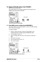
... system. 5. Insert the floppy disk then turn on the system. Adaptec 8130 LED setting (3-pin 8130LED1) (NCLV-D2/SATA model only) This jumper allows you to pins 2-3. 3. RECOVERY1 1 2 Normal (Default) NCLV-D2 Series BIOS recovery setting 2 3 BIOS Recovery ASUS NCLV-D2 Series 2-25 Prepare a floppy disk that contains the latest BIOS for the motherboard (xxxx-xxx.ROM...
... system. 5. Insert the floppy disk then turn on the system. Adaptec 8130 LED setting (3-pin 8130LED1) (NCLV-D2/SATA model only) This jumper allows you to pins 2-3. 3. RECOVERY1 1 2 Normal (Default) NCLV-D2 Series BIOS recovery setting 2 3 BIOS Recovery ASUS NCLV-D2 Series 2-25 Prepare a floppy disk that contains the latest BIOS for the motherboard (xxxx-xxx.ROM...

User Manual
Page 47
...IDE devices. This prevents incorrect insertion when you must configure the second drive as a slave device by setting its jumper accordingly. NCLV-D2 Series IDE connectors ASUS NCLV-D2 Series 2-27 Insert one end of the floppy disk drive. Pin 5 on the motherboard, a black connector for an Ultra... connection when using a FDD cable with a covered Pin 5. Refer to the hard disk documentation for an Ultra DMA 100/66 signal cable. NCLV-D2 Series Floppy disk drive connector 2 . IDE connectors (40-1 pin PRI_IDE1, SEC_IDE1) These connectors are for the jumper settings. • Pin ...
...IDE devices. This prevents incorrect insertion when you must configure the second drive as a slave device by setting its jumper accordingly. NCLV-D2 Series IDE connectors ASUS NCLV-D2 Series 2-27 Insert one end of the floppy disk drive. Pin 5 on the motherboard, a black connector for an Ultra... connection when using a FDD cable with a covered Pin 5. Refer to the hard disk documentation for an Ultra DMA 100/66 signal cable. NCLV-D2 Series Floppy disk drive connector 2 . IDE connectors (40-1 pin PRI_IDE1, SEC_IDE1) These connectors are for the jumper settings. • Pin ...
User Manual
Page 49
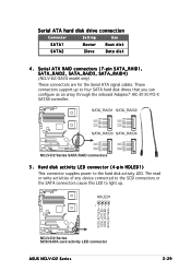
... SCSI connectors or the SATA connectors cause this LED to light up to the hard disk activity LED. HDLED1 1 SCSI_ACTLED+ SCSI_ACTLEDSCSI_ACTLEDSCSI_ACTLED+ NCLV-D2 Series SCSI/SATA card activity LED connector ASUS NCLV-D2 Series 2-29 Hard disk activity LED connector (4-pin HDLED1) This connector supplies power to four SATA hard disk drives that you can...
... SCSI connectors or the SATA connectors cause this LED to light up to the hard disk activity LED. HDLED1 1 SCSI_ACTLED+ SCSI_ACTLEDSCSI_ACTLEDSCSI_ACTLED+ NCLV-D2 Series SCSI/SATA card activity LED connector ASUS NCLV-D2 Series 2-29 Hard disk activity LED connector (4-pin HDLED1) This connector supplies power to four SATA hard disk drives that you can...

User Manual
Page 51
...5V USB_P6USB_P6+ GND NC USB+5V USB_P5USB_P5+ GND USB34 NCLV-D2 Series USB 2.0 connector The USB port module is purchased separately. Serial port connector (10-1 pin COM2) This connector is for a serial (COM) port. ASUS NCLV-D2 Series 2-31 This USB connector complies with USB 2.0 ...specification that supports up to a slot opening at the back of the system chassis. COM2 PIN 1 NCLV-D2 Series Serial port2 (COM2) connector The serial port module is ...
...5V USB_P6USB_P6+ GND NC USB+5V USB_P5USB_P5+ GND USB34 NCLV-D2 Series USB 2.0 connector The USB port module is purchased separately. Serial port connector (10-1 pin COM2) This connector is for a serial (COM) port. ASUS NCLV-D2 Series 2-31 This USB connector complies with USB 2.0 ...specification that supports up to a slot opening at the back of the system chassis. COM2 PIN 1 NCLV-D2 Series Serial port2 (COM2) connector The serial port module is ...

User Manual
Page 53
Backplane SMBus connector (6-1 pin BPSMB1) This connector allows you to connect SMBus (System Management Bus) devices. PSUSMB1 NCLV-D2 Series Power supply SMBus connector PSU_I2CCLK PSU_I2CDATA NC GND +3.3V Remote Sense ASUS NCLV-D2 Series 2-33 Devices communicate with an SMBus host and/or other SMBus devices using the SMBus interface. NC I2C_6_CLK# GND I2C_6_DATA# +5V 11. Power supply SMBus connector (5-pin PSUSMB1) This connector is for the power supply SMB cable, if your power supply supports the SMBus function. BPSMB1 1 NCLV-D2 Series SMBus connector 12.
Backplane SMBus connector (6-1 pin BPSMB1) This connector allows you to connect SMBus (System Management Bus) devices. PSUSMB1 NCLV-D2 Series Power supply SMBus connector PSU_I2CCLK PSU_I2CDATA NC GND +3.3V Remote Sense ASUS NCLV-D2 Series 2-33 Devices communicate with an SMBus host and/or other SMBus devices using the SMBus interface. NC I2C_6_CLK# GND I2C_6_DATA# +5V 11. Power supply SMBus connector (5-pin PSUSMB1) This connector is for the power supply SMB cable, if your power supply supports the SMBus function. BPSMB1 1 NCLV-D2 Series SMBus connector 12.
User Manual
Page 55
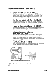
POWERLED+ GND POWERLEDMLED+ MLEDNC +5V GND GND SPKROUT HDLED+ HDLEDNMIBTN# GND POWERBTN# GND NC RESETBTN# GND PANEL1 NCLV-D2 Series System panel connector The system panel connector is for the system power LED. The IDE LED lights up when you to this...PANEL1) This connector supports several chassis-mounted functions. • System power LED (Green 3-pin PLED) This 3-pin connector is for the system power button. ASUS NCLV-D2 Series 2-35 14. Connect the HDD Activity LED cable to the HDD. • System warning speaker (Orange 4-pin SPEAKER) This 4-pin connector is ...
POWERLED+ GND POWERLEDMLED+ MLEDNC +5V GND GND SPKROUT HDLED+ HDLEDNMIBTN# GND POWERBTN# GND NC RESETBTN# GND PANEL1 NCLV-D2 Series System panel connector The system panel connector is for the system power LED. The IDE LED lights up when you to this...PANEL1) This connector supports several chassis-mounted functions. • System power LED (Green 3-pin PLED) This 3-pin connector is for the system power button. ASUS NCLV-D2 Series 2-35 14. Connect the HDD Activity LED cable to the HDD. • System warning speaker (Orange 4-pin SPEAKER) This 4-pin connector is ...
User Manual
Page 58
Chapter summary 3 3.1 Starting up for the first time 3-1 3.2 Powering off the computer 3-2 ASUS NCLV-D2 Series
Chapter summary 3 3.1 Starting up for the first time 3-1 3.2 Powering off the computer 3-2 ASUS NCLV-D2 Series


