User Guide
Page 6
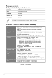
... summary CPU Memory Graphics Expansion slots Storage LAN Audio USB N3150I-C: Intel® Celeron® Quad-core Processor N3150 (Code Name: Braswell) N3050I-C: Intel® Celeron® Dual-core Processor N3050 (Code Name: Braswell) 2 x ...; HD Graphics support Multi-VGA output support: HDMI, D-Sub, LVDS - Supports D-sub with HD audio module in the front panel to www.asus.com for the following items. Motherboard ASUS N3150I-C or N3050I-C motherboard Cables 2 x Serial ATA 6.0 Gb/s cables Accessories 1 x I/O Shields Application DVD Support DVD Documentation User Guide If any of...
... summary CPU Memory Graphics Expansion slots Storage LAN Audio USB N3150I-C: Intel® Celeron® Quad-core Processor N3150 (Code Name: Braswell) N3050I-C: Intel® Celeron® Dual-core Processor N3050 (Code Name: Braswell) 2 x ...; HD Graphics support Multi-VGA output support: HDMI, D-Sub, LVDS - Supports D-sub with HD audio module in the front panel to www.asus.com for the following items. Motherboard ASUS N3150I-C or N3050I-C motherboard Cables 2 x Serial ATA 6.0 Gb/s cables Accessories 1 x I/O Shields Application DVD Support DVD Documentation User Guide If any of...

User Guide
Page 9
ASUS N3150I-C / N3050I-C 1-1 Failure to do so may cause severe damage to avoid touching the ICs on them. • Whenever you uninstall any component, place it on a ...
ASUS N3150I-C / N3050I-C 1-1 Failure to do so may cause severe damage to avoid touching the ICs on them. • Whenever you uninstall any component, place it on a ...
User Guide
Page 11
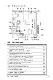
...connectors (7-pin SATA6G_1, SATA6G_2) 8. Flat panel display brightness (8-pin LCD_BLKT_PANEL) 12. Display panel power connector (2-pin PANEL_SW) 15. N3150I-C: Intel® Celeron Quad-core Processor N3150 N3050I-C: Intel® Celeron Dual-core Processor N3050 5. LVDS connector (40-pin LVDS...chassis fan connectors (4-pin CPU_FAN, 4-pin CHA_FAN) 3. Clear RTC RAM (2-pin CLCMOS) 17. TPM connector (14-1 pin TPM) ASUS N3150I-C / N3050I-C Mini PCIe SATA6G_1 SATA6G_2 N3150I-C N3050I-C DDR3_DIMM_A1 (64bit, 240-pin module) DDR3_DIMM_B1 (64bit, 240-pin module) EATX_PWR 17.0cm(6.7in) 5 7 Page 1-...
...connectors (7-pin SATA6G_1, SATA6G_2) 8. Flat panel display brightness (8-pin LCD_BLKT_PANEL) 12. Display panel power connector (2-pin PANEL_SW) 15. N3150I-C: Intel® Celeron Quad-core Processor N3150 N3050I-C: Intel® Celeron Dual-core Processor N3050 5. LVDS connector (40-pin LVDS...chassis fan connectors (4-pin CPU_FAN, 4-pin CHA_FAN) 3. Clear RTC RAM (2-pin CLCMOS) 17. TPM connector (14-1 pin TPM) ASUS N3150I-C / N3050I-C Mini PCIe SATA6G_1 SATA6G_2 N3150I-C N3050I-C DDR3_DIMM_A1 (64bit, 240-pin module) DDR3_DIMM_B1 (64bit, 240-pin module) EATX_PWR 17.0cm(6.7in) 5 7 Page 1-...
User Guide
Page 13
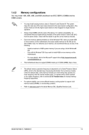
... 4GB or more efficient memory cooling system to support a full memory load (2 DIMMs) or overclocking condition. • Refer to www.asus.com for the OS can be about 3GB or less. ASUS N3150I-C / N3050I-C 1-5 For effective use a more memory on the motherboard, the actual usable memory for the latest Memory QVL (Qualified Vendors...
... 4GB or more efficient memory cooling system to support a full memory load (2 DIMMs) or overclocking condition. • Refer to www.asus.com for the OS can be about 3GB or less. ASUS N3150I-C / N3050I-C 1-5 For effective use a more memory on the motherboard, the actual usable memory for the latest Memory QVL (Qualified Vendors...
User Guide
Page 15
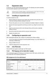
... installing the expansion card, configure it and make the necessary hardware settings for information on the system and change the necessary BIOS settings, if any. ASUS N3150I-C / N3050I-C 1-7 shared - - - Before installing the expansion card, read the documentation that you intend to the card. 3. shared - - - - - - - - shared - - - - - - - - - - shared - - - - - Remove the system unit cover (if...
... installing the expansion card, configure it and make the necessary hardware settings for information on the system and change the necessary BIOS settings, if any. ASUS N3150I-C / N3050I-C 1-7 shared - - - Before installing the expansion card, read the documentation that you intend to the card. 3. shared - - - - - - - - shared - - - - - - - - - - shared - - - - - Remove the system unit cover (if...

User Guide
Page 17
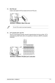
...for a chassis-mounted intrusion detection sensor or switch. Display panel backlight power selector (3-pin BLKT_PWR_SEL) N3150I-C N3050I-C BLKT_PWR_SEL 12 23 12V 5V (Default) N3150I-C / N3050I-C Display panel backlight power selection Pins 1-2 (Default) 2-3 Setting 12V 5V ASUS N3150I-C / N3050I-C 1-9 Remove the jumper caps only when you intend to this connector when a ... CHASSIS) This connector is then generated as a chassis intrusion event. By default, the pins labeled "Intruder" are shorted with a jumper cap. CHASSIS N3150I-C N3050I-C +5VSB_MB Chassis Signal GND PIN...
...for a chassis-mounted intrusion detection sensor or switch. Display panel backlight power selector (3-pin BLKT_PWR_SEL) N3150I-C N3050I-C BLKT_PWR_SEL 12 23 12V 5V (Default) N3150I-C / N3050I-C Display panel backlight power selection Pins 1-2 (Default) 2-3 Setting 12V 5V ASUS N3150I-C / N3050I-C 1-9 Remove the jumper caps only when you intend to this connector when a ... CHASSIS) This connector is then generated as a chassis intrusion event. By default, the pins labeled "Intruder" are shorted with a jumper cap. CHASSIS N3150I-C N3050I-C +5VSB_MB Chassis Signal GND PIN...
User Guide
Page 19
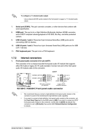
... item in the front panel to [HD Audio]. This port connects a modem, or other protected content. 9. AAFP N3150I-C N3050I-C SENSE2_RETUR SENSE1_RETUR NC AGND PORT2 L NC SENSE_SEND PORT2 R NC PORT1 R NC PORT1 L AGND PIN 1 Line... out_L NC Line out_R MICPWR MIC2 PIN 1 HD-audio-compliant pin definition Legacy AC'97 compliant definition N3150I-C / N3050I-C Front panel audio connector • We recommend that supports either HD Audio or legacy AC`97 ...COM1). Front panel audio connector (10-1 pin AAFP) This connector is for details. ASUS N3150I-C / N3050I-C 1-11
... item in the front panel to [HD Audio]. This port connects a modem, or other protected content. 9. AAFP N3150I-C N3050I-C SENSE2_RETUR SENSE1_RETUR NC AGND PORT2 L NC SENSE_SEND PORT2 R NC PORT1 R NC PORT1 L AGND PIN 1 Line... out_L NC Line out_R MICPWR MIC2 PIN 1 HD-audio-compliant pin definition Legacy AC'97 compliant definition N3150I-C / N3050I-C Front panel audio connector • We recommend that supports either HD Audio or legacy AC`97 ...COM1). Front panel audio connector (10-1 pin AAFP) This connector is for details. ASUS N3150I-C / N3050I-C 1-11

User Guide
Page 21
...-1 pin TPM) This connector supports a Trusted Platform Module (TPM) system, which can securely store keys, digital certificates, passwords and data. ASUS N3150I-C / N3050I-C 1-13 The system may become unstable or may not boot up . • We recommend that you use a power supply... you are designed to the Recommended Power Supply Wattage Calculator at http://support.asus. N3150I-C N3050I-C TPM PIN 1 F_LAD0 F_LAD1 F_LAD2 F_LAD3 +3V +3V C_PCICLK_TPM GND F_FRAME# F_SERIRQ F_CLKRUN S_PCIRST#_TBD +3VSB N3150I-C / N3050I-C TPM connector The TPM module is inadequate. • If...
...-1 pin TPM) This connector supports a Trusted Platform Module (TPM) system, which can securely store keys, digital certificates, passwords and data. ASUS N3150I-C / N3050I-C 1-13 The system may become unstable or may not boot up . • We recommend that you use a power supply... you are designed to the Recommended Power Supply Wattage Calculator at http://support.asus. N3150I-C N3050I-C TPM PIN 1 F_LAD0 F_LAD1 F_LAD2 F_LAD3 +3V +3V C_PCICLK_TPM GND F_FRAME# F_SERIRQ F_CLKRUN S_PCIRST#_TBD +3VSB N3150I-C / N3050I-C TPM connector The TPM module is inadequate. • If...

User Guide
Page 23
... data is read from or written to this connector. Connect the HDD Activity LED cable to [LVDS]. Ground HWRST# (NC) N3150I-C N3050I-C +HDD_LED- N3150I-C N3050I-C LVDS PIN 1 N3150I-C / N3050I-C LVDS connector The LVDS output is for details. See section 2.5.3 SoC Configuration for the HDD Activity LED. PWR_BTN ... reboot without turning off the system power. 9. LVDS connector (40-pin LVDS) This connector is in the BIOS setup to this connector. ASUS N3150I-C / N3050I-C 1-15 The HD LED lights up when you turn on the system power, and blinks when the system is for the ...
... data is read from or written to this connector. Connect the HDD Activity LED cable to [LVDS]. Ground HWRST# (NC) N3150I-C N3050I-C +HDD_LED- N3150I-C N3050I-C LVDS PIN 1 N3150I-C / N3050I-C LVDS connector The LVDS output is for details. See section 2.5.3 SoC Configuration for the HDD Activity LED. PWR_BTN ... reboot without turning off the system power. 9. LVDS connector (40-pin LVDS) This connector is in the BIOS setup to this connector. ASUS N3150I-C / N3050I-C 1-15 The HD LED lights up when you turn on the system power, and blinks when the system is for the ...
User Guide
Page 25
... O_LPT_XSLIN#_R GND GND GND GND GND GND GND GND O_LPT_XSTB#_R O_LPT_XPD0_R O_LPT_XPD1_R O_LPT_XPD2_R O_LPT_XPD3_R O_LPT_XPD4_R O_LPT_XPD5_R O_LPT_XPD6_R O_LPT_XPD7_R O_LPT_ACK#_R O_LPT_BUSY_R O_LPT_PE_R O_LPT_SLCT_R N3150I-C N3050I-C ASUS N3150I-C / N3050I-C 1-17 LPT connector (26-1 pin LPT) The LPT (Line Printing Terminal) connector supports devices such as IEEE 1284, which is purchased separately. 14...
... O_LPT_XSLIN#_R GND GND GND GND GND GND GND GND O_LPT_XSTB#_R O_LPT_XPD0_R O_LPT_XPD1_R O_LPT_XPD2_R O_LPT_XPD3_R O_LPT_XPD4_R O_LPT_XPD5_R O_LPT_XPD6_R O_LPT_XPD7_R O_LPT_ACK#_R O_LPT_BUSY_R O_LPT_PE_R O_LPT_SLCT_R N3150I-C N3050I-C ASUS N3150I-C / N3050I-C 1-17 LPT connector (26-1 pin LPT) The LPT (Line Printing Terminal) connector supports devices such as IEEE 1284, which is purchased separately. 14...

User Guide
Page 27
...4. 1.9 Windows® 7 64-bit and USB 3.0 driver installation Based on your system and press F8 during Windows® 7 64-bit installation. Requirement: • 1 x ASUS support DVD • 1 x Windows® 7 64-bit installation source • 1 x SATA ODD • 1 x USB device (ODD or storage) The USB storage...device as the boot device. Insert the Windows® 7 64-bit installation DVD into a SATA ODD on a working system. 2. ASUS N3150I-C / N3050I-C 1-19 Insert the ASUS support DVD into a USB ODD, or copy all files on the Windows® 7 64-bit installation DVD to enter the boot...
...4. 1.9 Windows® 7 64-bit and USB 3.0 driver installation Based on your system and press F8 during Windows® 7 64-bit installation. Requirement: • 1 x ASUS support DVD • 1 x Windows® 7 64-bit installation source • 1 x SATA ODD • 1 x USB device (ODD or storage) The USB storage...device as the boot device. Insert the Windows® 7 64-bit installation DVD into a SATA ODD on a working system. 2. ASUS N3150I-C / N3050I-C 1-19 Insert the ASUS support DVD into a USB ODD, or copy all files on the Windows® 7 64-bit installation DVD to enter the boot...

User Guide
Page 29
Burn this ISO file onto an empty DVD to enter the boot screen. ASUS N3150I-C / N3050I-C 1-21 On your system. 3. Requirement: • 1 x ASUS support DVD • 1 x Windows® 7 64-bit installation source • 1 x Working system (PC or notebook) • 1 x SATA ODD 1. Edit the ISO... file and add both "Auto_Unattend.xml" and "Auto_Unattend" folder from the root directory of the ASUS supporting DVD to your working system, create an ISO image file of the Windows® 7 64-bit installation source using a modified Windows® 7 64...
Burn this ISO file onto an empty DVD to enter the boot screen. ASUS N3150I-C / N3050I-C 1-21 On your system. 3. Requirement: • 1 x ASUS support DVD • 1 x Windows® 7 64-bit installation source • 1 x Working system (PC or notebook) • 1 x SATA ODD 1. Edit the ISO... file and add both "Auto_Unattend.xml" and "Auto_Unattend" folder from the root directory of the ASUS supporting DVD to your working system, create an ISO image file of the Windows® 7 64-bit installation source using a modified Windows® 7 64...
User Guide
Page 31
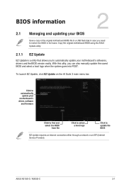
... the AI Suite 3 main menu bar. With this utlity, you need to restore the BIOS in the future. Copy the original motherboard BIOS using the ASUS Update utility. 2.1.1 EZ Update EZ Update is a utility that allows you to update the BIOS EZ Update requires an Internet connection either through a network or... file to a USB flash disk in case you can also manually update the saved BIOS and select a boot logo when the system goes into POST. ASUS N3150I-C / N3050I-C 2-1 BIOS information 2 2.1 Managing and updating your motherboard's softwares, drivers and the BIOS version easily.
... the AI Suite 3 main menu bar. With this utlity, you need to restore the BIOS in the future. Copy the original motherboard BIOS using the ASUS Update utility. 2.1.1 EZ Update EZ Update is a utility that allows you to update the BIOS EZ Update requires an Internet connection either through a network or... file to a USB flash disk in case you can also manually update the saved BIOS and select a boot logo when the system goes into POST. ASUS N3150I-C / N3050I-C 2-1 BIOS information 2 2.1 Managing and updating your motherboard's softwares, drivers and the BIOS version easily.
User Guide
Page 33
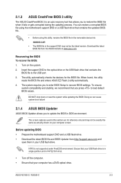
...allows you to load default BIOS values. To ensure system compatibility and stability, we recommend that contains the BIOS file to the USB port. 3. ASUS N3150I-C / N3050I-C 2-3 Insert the support DVD to the optical drive or the USB flash drive that you to recover BIOS settings. You can cause... system boot failure! 2.1.4 ASUS BIOS Updater ASUS BIOS Updater allows you press to restore the BIOS file when it fails or gets corrupted during the updating process. The utility automatically...
...allows you to load default BIOS values. To ensure system compatibility and stability, we recommend that contains the BIOS file to the USB port. 3. ASUS N3150I-C / N3050I-C 2-3 Insert the support DVD to the optical drive or the USB flash drive that you to recover BIOS settings. You can cause... system boot failure! 2.1.4 ASUS BIOS Updater ASUS BIOS Updater allows you press to restore the BIOS file when it fails or gets corrupted during the updating process. The utility automatically...

User Guide
Page 35
ASUS N3150I-C / N3050I-C 2-5 Press to switch from Drives panel to Files panel then press keys to prevent system boot failaure. Select Yes then press . DO NOT shut ...
ASUS N3150I-C / N3050I-C 2-5 Press to switch from Drives panel to Files panel then press keys to prevent system boot failaure. Select Yes then press . DO NOT shut ...

User Guide
Page 37
... profile and boot device priority. To access the Advanced Mode, click Advanced Mode(F7) or press . Refer to the system. The default screen for details. ASUS N3150I-C / N3050I-C 2-7 2.2.1 EZ Mode By default, the EZ Mode screen appears when you enter the BIOS setup program.
... profile and boot device priority. To access the Advanced Mode, click Advanced Mode(F7) or press . Refer to the system. The default screen for details. ASUS N3150I-C / N3050I-C 2-7 2.2.1 EZ Mode By default, the EZ Mode screen appears when you enter the BIOS setup program.

User Guide
Page 39
... all BIOS items in the menu and change the settings. MyFavorites (F3) This button above the menu bar contains the navigation keys for more information. ASUS N3150I-C / N3050I-C 2-9
... all BIOS items in the menu and change the settings. MyFavorites (F3) This button above the menu bar contains the navigation keys for more information. ASUS N3150I-C / N3050I-C 2-9

User Guide
Page 41
... panel, then click the submenu that you want to save in MyFavorites screen. Click Exit (ESC) or press key to view the saved BIOS items. ASUS N3150I-C / N3050I-C 2-11 Press on your keyboard or click Setup Tree Map screen. from the submenu panel and click . Adding items to open 2. On the Setup...
... panel, then click the submenu that you want to save in MyFavorites screen. Click Exit (ESC) or press key to view the saved BIOS items. ASUS N3150I-C / N3050I-C 2-11 Press on your keyboard or click Setup Tree Map screen. from the submenu panel and click . Adding items to open 2. On the Setup...

User Guide
Page 43
... prompted. To clear the user password, follow the same steps as in changing an administrator password, but press when prompted to create/confirm the password. ASUS N3150I-C / N3050I-C 2-13 From the Create New Password box, key in a password, then press . 3. Confirm the password when prompted. After you clear the password, the User...
... prompted. To clear the user password, follow the same steps as in changing an administrator password, but press when prompted to create/confirm the password. ASUS N3150I-C / N3050I-C 2-13 From the Create New Password box, key in a password, then press . 3. Confirm the password when prompted. After you clear the password, the User...

User Guide
Page 45
...-215x (21.5\x22)] [Wibtek A21 (21.5\x22)] [Wibtek A23 (23.6\x22)] [Jumper Sail (21.5\x22)] [Pixxo HPA206D (21.5\x22)] [22AM33NB (21.5\x22)] [3N0D (21.5\x22)] ASUS N3150I-C / N3050I-C 2-15
...-215x (21.5\x22)] [Wibtek A21 (21.5\x22)] [Wibtek A23 (23.6\x22)] [Jumper Sail (21.5\x22)] [Pixxo HPA206D (21.5\x22)] [22AM33NB (21.5\x22)] [3N0D (21.5\x22)] ASUS N3150I-C / N3050I-C 2-15


