User Guide
Page 6
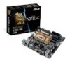
.... Package contents Check your motherboard package for the latest Memory QVL (Qualified Vendors List). N3150I-C / N3050I-C specifications summary CPU Memory Graphics Expansion slots Storage LAN Audio USB N3150I-C: Intel® Celeron® Quad-core Processor N3150 (Code Name: Braswell) N3050I-C: ...x 2160 @30Hz - Supports D-sub with max. Supports LVDS with HD audio module in the front panel to www.asus.com for the following items. Motherboard ASUS N3150I-C or N3050I-C motherboard Cables 2 x Serial ATA 6.0 Gb/s cables Accessories 1 x I/O Shields Application DVD Support DVD...
.... Package contents Check your motherboard package for the latest Memory QVL (Qualified Vendors List). N3150I-C / N3050I-C specifications summary CPU Memory Graphics Expansion slots Storage LAN Audio USB N3150I-C: Intel® Celeron® Quad-core Processor N3150 (Code Name: Braswell) N3050I-C: ...x 2160 @30Hz - Supports D-sub with max. Supports LVDS with HD audio module in the front panel to www.asus.com for the following items. Motherboard ASUS N3150I-C or N3050I-C motherboard Cables 2 x Serial ATA 6.0 Gb/s cables Accessories 1 x I/O Shields Application DVD Support DVD...

User Guide
Page 9
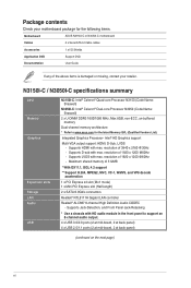
... you install or remove any component, ensure that the ATX power supply is switched off or the power cord is detached from the power supply. ASUS N3150I-C / N3050I-C 1-1 Product introduction 1 1.1 Before you proceed Take note of the following precautions before you install motherboard components or change any motherboard settings. • Unplug the...
... you install or remove any component, ensure that the ATX power supply is switched off or the power cord is detached from the power supply. ASUS N3150I-C / N3050I-C 1-1 Product introduction 1 1.1 Before you proceed Take note of the following precautions before you install motherboard components or change any motherboard settings. • Unplug the...
User Guide
Page 11
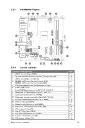
N3150I-C: Intel® Celeron Quad-core Processor N3150 N3050I-C: Intel® Celeron Dual-core Processor N3050 5. Serial ATA 6.0Gb/s connectors (7-pin SATA6G_1, SATA6G_2) 8. Flat panel display ...) 15. USB 2.0 connector (10-pin USBE34) 2. LVDS connector (40-pin LVDS) 13. LPT connector (26-1 pin LPT) 16. TPM connector (14-1 pin TPM) ASUS N3150I-C / N3050I-C Mini PCIe SATA6G_1 SATA6G_2 N3150I-C N3050I-C DDR3_DIMM_A1 (64bit, 240-pin module) DDR3_DIMM_B1 (64bit, 240-pin module) EATX_PWR 17.0cm(6.7in) 5 7 Page 1-14 1-12 1-14 1-4 1-13 1-4 1-15 1-8 1-15...
N3150I-C: Intel® Celeron Quad-core Processor N3150 N3050I-C: Intel® Celeron Dual-core Processor N3050 5. Serial ATA 6.0Gb/s connectors (7-pin SATA6G_1, SATA6G_2) 8. Flat panel display ...) 15. USB 2.0 connector (10-pin USBE34) 2. LVDS connector (40-pin LVDS) 13. LPT connector (26-1 pin LPT) 16. TPM connector (14-1 pin TPM) ASUS N3150I-C / N3050I-C Mini PCIe SATA6G_1 SATA6G_2 N3150I-C N3050I-C DDR3_DIMM_A1 (64bit, 240-pin module) DDR3_DIMM_B1 (64bit, 240-pin module) EATX_PWR 17.0cm(6.7in) 5 7 Page 1-14 1-12 1-14 1-4 1-13 1-4 1-15 1-8 1-15...
User Guide
Page 13
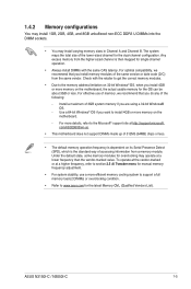
... may install varying memory sizes in Channel A and Channel B. To operate at the vendor-marked or at a higher frequency, refer to www.asus.com for the dual-channel configuration. The system maps the total size of memory, we recommend that you are using a 32-bit Windows®...8226; Always install DIMMs with the retailer to get the correct memory modules. • Due to the Microsoft® support site at http://support.microsoft. ASUS N3150I-C / N3050I-C 1-5 Any excess memory from the higher-sized channel is the standard way of the same version or date code (D/C) from a memory module....
... may install varying memory sizes in Channel A and Channel B. To operate at the vendor-marked or at a higher frequency, refer to www.asus.com for the dual-channel configuration. The system maps the total size of memory, we recommend that you are using a 32-bit Windows®...8226; Always install DIMMs with the retailer to get the correct memory modules. • Due to the Microsoft® support site at http://support.microsoft. ASUS N3150I-C / N3050I-C 1-5 Any excess memory from the higher-sized channel is the standard way of the same version or date code (D/C) from a memory module....
User Guide
Page 15
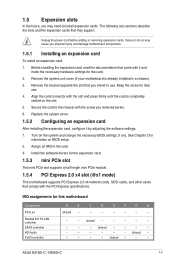
... the chassis with it by adjusting the software settings. 1. Turn on the slot. 5. See Chapter 2 for the card. 2. Assign an IRQ to install expansion cards. ASUS N3150I-C / N3050I-C 1-7 Unplug the power cord before adding or removing expansion cards. Keep the screw for this motherboard Component PCIe x4 Realtek 8111H LAN controller SATA...
... the chassis with it by adjusting the software settings. 1. Turn on the slot. 5. See Chapter 2 for the card. 2. Assign an IRQ to install expansion cards. ASUS N3150I-C / N3050I-C 1-7 Unplug the power cord before adding or removing expansion cards. Keep the screw for this motherboard Component PCIe x4 Realtek 8111H LAN controller SATA...

User Guide
Page 17
..., the pins labeled "Intruder" are shorted with a jumper cap. Display panel backlight power selector (3-pin BLKT_PWR_SEL) N3150I-C N3050I-C BLKT_PWR_SEL 12 23 12V 5V (Default) N3150I-C / N3050I-C Display panel backlight power selection Pins 1-2 (Default) 2-3 Setting 12V 5V ASUS N3150I-C / N3050I-C 1-9 Connect one end of the chassis intrusion sensor or switch cable to use the chassis...
..., the pins labeled "Intruder" are shorted with a jumper cap. Display panel backlight power selector (3-pin BLKT_PWR_SEL) N3150I-C N3050I-C BLKT_PWR_SEL 12 23 12V 5V (Default) N3150I-C / N3050I-C Display panel backlight power selection Pins 1-2 (Default) 2-3 Setting 12V 5V ASUS N3150I-C / N3050I-C 1-9 Connect one end of the chassis intrusion sensor or switch cable to use the chassis...
User Guide
Page 19
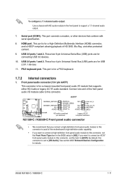
...specification. 8. This port is for details. These two 9-pin Universal Serial Bus (USB) ports are for connecting USB 3.0 devices. 10. AAFP N3150I-C N3050I-C SENSE2_RETUR SENSE1_RETUR NC AGND PORT2 L NC SENSE_SEND PORT2 R NC PORT1 R NC PORT1 L AGND PIN 1 Line out_L NC Line out_R...audio connector (10-1 pin AAFP) This connector is for a chassis-mounted front panel audio I /O module cable to this connector, set to [HD]. ASUS N3150I-C / N3050I-C 1-11 USB 2.0 ports 1 and 2. This port is for a PS/2 keyboard. 1.7.2 Internal connectors 1. By default, this connector is...
...specification. 8. This port is for details. These two 9-pin Universal Serial Bus (USB) ports are for connecting USB 3.0 devices. 10. AAFP N3150I-C N3050I-C SENSE2_RETUR SENSE1_RETUR NC AGND PORT2 L NC SENSE_SEND PORT2 R NC PORT1 R NC PORT1 L AGND PIN 1 Line out_L NC Line out_R...audio connector (10-1 pin AAFP) This connector is for a chassis-mounted front panel audio I /O module cable to this connector, set to [HD]. ASUS N3150I-C / N3050I-C 1-11 USB 2.0 ports 1 and 2. This port is for a PS/2 keyboard. 1.7.2 Internal connectors 1. By default, this connector is...

User Guide
Page 21
... system, refer to the Recommended Power Supply Wattage Calculator at http://support.asus. ATX power connectors (24-pin EATXPWR, 4-pin ATX12V) These connectors are for details. 5. ATX12V EATXPWR +12V DC +12V DC N3150I-C N3050I-C +3 Volts +12 Volts +12 Volts +5V Standby Power...Find the proper orientation and push down firmly until the connectors completely fit. ASUS N3150I-C / N3050I-C 1-13 A TPM system also helps enhance network security, protects digital identities, and ensures platform integrity. N3150I-C N3050I-C TPM PIN 1 F_LAD0 F_LAD1 F_LAD2 F_LAD3 +3V +3V C_PCICLK_TPM ...
... system, refer to the Recommended Power Supply Wattage Calculator at http://support.asus. ATX power connectors (24-pin EATXPWR, 4-pin ATX12V) These connectors are for details. 5. ATX12V EATXPWR +12V DC +12V DC N3150I-C N3050I-C +3 Volts +12 Volts +12 Volts +5V Standby Power...Find the proper orientation and push down firmly until the connectors completely fit. ASUS N3150I-C / N3050I-C 1-13 A TPM system also helps enhance network security, protects digital identities, and ensures platform integrity. N3150I-C N3050I-C TPM PIN 1 F_LAD0 F_LAD1 F_LAD2 F_LAD3 +3V +3V C_PCICLK_TPM ...

User Guide
Page 23
RESET N3150I-C / N3050I-C System panel connector • System power LED (2-pin PWRLED) This 2-pin connector is for an LCD monitor that supports Low-voltage Differential Signaling (LVDS) ... a LVDS monitor, set the IGD Flat Panel item in sleep mode. • Hard disk drive activity LED (2-pin +HDLED) This 2-pin connector is for details. ASUS N3150I-C / N3050I-C 1-15 Connect the chassis power LED cable to this connector. F_PANEL +PWR LED- PWR_BTN PWR_LED+ PWR_LEDPWR GND PIN 1 HDD_LED+ HDD_LED...
RESET N3150I-C / N3050I-C System panel connector • System power LED (2-pin PWRLED) This 2-pin connector is for an LCD monitor that supports Low-voltage Differential Signaling (LVDS) ... a LVDS monitor, set the IGD Flat Panel item in sleep mode. • Hard disk drive activity LED (2-pin +HDLED) This 2-pin connector is for details. ASUS N3150I-C / N3050I-C 1-15 Connect the chassis power LED cable to this connector. F_PANEL +PWR LED- PWR_BTN PWR_LED+ PWR_LEDPWR GND PIN 1 HDD_LED+ HDD_LED...
User Guide
Page 25
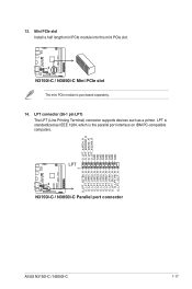
...LPT (Line Printing Terminal) connector supports devices such as IEEE 1284, which is the parallel port interface on IBM PC-compatible computers. N3150I-C N3050I-C 13. N3150I-C / N3050I-C Mini PCIe slot The mini PCIe module is standardized as a printer. LPT is purchased separately. 14. Mini PCIe slot... Install a half length mini PCIe module into this mini PCIe slot. LPT PIN 1 N3150I-C / N3050I-C Parallel port connector O_LPT_XAFD#_R O_LPT_ERROR#_R O_LPT_XINIT#_R O_LPT_XSLIN#_R GND GND GND GND GND GND GND GND O_LPT_XSTB#_R ...
...LPT (Line Printing Terminal) connector supports devices such as IEEE 1284, which is the parallel port interface on IBM PC-compatible computers. N3150I-C N3050I-C 13. N3150I-C / N3050I-C Mini PCIe slot The mini PCIe module is standardized as a printer. LPT is purchased separately. 14. Mini PCIe slot... Install a half length mini PCIe module into this mini PCIe slot. LPT PIN 1 N3150I-C / N3050I-C Parallel port connector O_LPT_XAFD#_R O_LPT_ERROR#_R O_LPT_XINIT#_R O_LPT_XSLIN#_R GND GND GND GND GND GND GND GND O_LPT_XSTB#_R ...

User Guide
Page 27
... working system. 2. Method 1: Using SATA ODD & USB devices Load USB 3.0 drivers using the ASUS support DVD and install Windows® 7 64-bit using a USB device. ASUS N3150I-C / N3050I-C 1-19 Insert the ASUS support DVD into a USB ODD, or copy all files on preloading USB 3.0 drivers and installing ... a SATA ODD on your Braswell series platform. 3. Connect the USB ODD or USB storage device to your Braswell series platform. 4. Requirement: • 1 x ASUS support DVD • 1 x Windows® 7 64-bit installation source • 1 x SATA ODD • 1 x USB device (ODD or storage) ...
... working system. 2. Method 1: Using SATA ODD & USB devices Load USB 3.0 drivers using the ASUS support DVD and install Windows® 7 64-bit using a USB device. ASUS N3150I-C / N3050I-C 1-19 Insert the ASUS support DVD into a USB ODD, or copy all files on preloading USB 3.0 drivers and installing ... a SATA ODD on your Braswell series platform. 3. Connect the USB ODD or USB storage device to your Braswell series platform. 4. Requirement: • 1 x ASUS support DVD • 1 x Windows® 7 64-bit installation source • 1 x SATA ODD • 1 x USB device (ODD or storage) ...

User Guide
Page 29
...Windows® 7 64-bit using a third-party ISO software. 2. On your working system, create an ISO image file of the ASUS supporting DVD to your system. 3. Edit the ISO file and add both "Auto_Unattend.xml" and "Auto_Unattend" folder from the root directory...Copy both "Auto_Unattend.xml" and "Auto_Unattend" folder into an ODD on your Braswell series platform. 6. ASUS N3150I-C / N3050I-C 1-21 Insert the modified Windows® 7 64-bit installation DVD into the ISO file. 4. Requirement: • 1 x ASUS support DVD • 1 x Windows® 7 64-bit installation source • 1 x ...
...Windows® 7 64-bit using a third-party ISO software. 2. On your working system, create an ISO image file of the ASUS supporting DVD to your system. 3. Edit the ISO file and add both "Auto_Unattend.xml" and "Auto_Unattend" folder from the root directory...Copy both "Auto_Unattend.xml" and "Auto_Unattend" folder into an ODD on your Braswell series platform. 6. ASUS N3150I-C / N3050I-C 1-21 Insert the modified Windows® 7 64-bit installation DVD into the ISO file. 4. Requirement: • 1 x ASUS support DVD • 1 x Windows® 7 64-bit installation source • 1 x ...
User Guide
Page 31
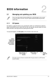
... Update EZ Update is a utility that allows you can also manually update the saved BIOS and select a boot logo when the system goes into POST. ASUS N3150I-C / N3050I-C 2-1 With this utlity, you to update the BIOS EZ Update requires an Internet connection either through a network or an ISP (Internet Service Provider). BIOS...
... Update EZ Update is a utility that allows you can also manually update the saved BIOS and select a boot logo when the system goes into POST. ASUS N3150I-C / N3050I-C 2-1 With this utlity, you to update the BIOS EZ Update requires an Internet connection either through a network or an ISP (Internet Service Provider). BIOS...
User Guide
Page 33
... reset the system while updating the BIOS! You can cause system boot failure! 2.1.4 ASUS BIOS Updater ASUS BIOS Updater allows you to the USB port. 3. NTFS is not supported under FreeDOS environment. ASUS N3150I-C / N3050I-C 2-3 Ensure that your USB flash drive is in single partition and ...in your computer has a DVD optical drive. Download the latest BIOS file from http://support.asus.com and save them in FAT32/16 format. •...
... reset the system while updating the BIOS! You can cause system boot failure! 2.1.4 ASUS BIOS Updater ASUS BIOS Updater allows you to the USB port. 3. NTFS is not supported under FreeDOS environment. ASUS N3150I-C / N3050I-C 2-3 Ensure that your USB flash drive is in single partition and ...in your computer has a DVD optical drive. Download the latest BIOS file from http://support.asus.com and save them in FAT32/16 format. •...

User Guide
Page 35
... BIOS default settings to confirm the BIOS update. After the BIOS Updater checks the selected BIOS file, select Yes to ensure system compatibility and stability. ASUS N3150I-C / N3050I-C 2-5 Drives panel ASUSTeK BIOS Updater for details. DO NOT shut down or reset the system while updating the BIOS to prevent system boot failaure...
... BIOS default settings to confirm the BIOS update. After the BIOS Updater checks the selected BIOS file, select Yes to ensure system compatibility and stability. ASUS N3150I-C / N3050I-C 2-5 Drives panel ASUSTeK BIOS Updater for details. DO NOT shut down or reset the system while updating the BIOS to prevent system boot failaure...

User Guide
Page 37
ASUS N3150I-C / N3050I-C 2-7 The default screen for details. The EZ Mode provides you an overview of the BIOS setup program Loads optimized default settings Shows the bootable ...
ASUS N3150I-C / N3050I-C 2-7 The default screen for details. The EZ Mode provides you an overview of the BIOS setup program Loads optimized default settings Shows the bootable ...

User Guide
Page 39
...; You can select for the BIOS setup program. Refer to section 2.3 My Favorites for that menu. To display the submenu, select the item and press . ASUS N3150I-C / N3050I-C 2-9 For example, selecting Main shows the Main menu items. The other items (My Favorites, Advanced, Monitor, Boot, Tool, and Exit) on the menu bar...
...; You can select for the BIOS setup program. Refer to section 2.3 My Favorites for that menu. To display the submenu, select the item and press . ASUS N3150I-C / N3050I-C 2-9 For example, selecting Main shows the Main menu items. The other items (My Favorites, Advanced, Monitor, Boot, Tool, and Exit) on the menu bar...

User Guide
Page 41
... in MyFavorites screen. Main menu panel Submenu panel Selected shortcut items 3. from the submenu panel and click . Adding items to view the saved BIOS items. ASUS N3150I-C / N3050I-C 2-11 On the Setup Tree Map screen, select the BIOS items that you want to My Favorite items: • User-managed items such as...
... in MyFavorites screen. Main menu panel Submenu panel Selected shortcut items 3. from the submenu panel and click . Adding items to view the saved BIOS items. ASUS N3150I-C / N3050I-C 2-11 On the Setup Tree Map screen, select the BIOS items that you want to My Favorite items: • User-managed items such as...

User Guide
Page 43
... you set a user password, you have set a password, this item shows Installed. From the Create New Password box, key in the current password, then press . 3. ASUS N3150I-C / N3050I-C 2-13 Select the User Password item and press . 2. Select the User Password item and press . 2. From the Create New Password box, key in the...
... you set a user password, you have set a password, this item shows Installed. From the Create New Password box, key in the current password, then press . 3. ASUS N3150I-C / N3050I-C 2-13 Select the User Password item and press . 2. Select the User Password item and press . 2. From the Create New Password box, key in the...

User Guide
Page 45
...-215x (21.5\x22)] [Wibtek A21 (21.5\x22)] [Wibtek A23 (23.6\x22)] [Jumper Sail (21.5\x22)] [Pixxo HPA206D (21.5\x22)] [22AM33NB (21.5\x22)] [3N0D (21.5\x22)] ASUS N3150I-C / N3050I-C 2-15 Configuration options: [Auto] [Disabled] [Enabled] The following item appears only when you to set the CPU cores to automatically set the maximum C-state...
...-215x (21.5\x22)] [Wibtek A21 (21.5\x22)] [Wibtek A23 (23.6\x22)] [Jumper Sail (21.5\x22)] [Pixxo HPA206D (21.5\x22)] [22AM33NB (21.5\x22)] [3N0D (21.5\x22)] ASUS N3150I-C / N3050I-C 2-15 Configuration options: [Auto] [Disabled] [Enabled] The following item appears only when you to set the CPU cores to automatically set the maximum C-state...


