MEL User Manual
Page 2
... INACCURACIES THAT MAY APPEAR IN THIS MANUAL, INCLUDING THE PRODUCTS AND SOFTWARE DESCRIBED IN IT. Product Name: ASUS MEL Manual Revision: 1.01 E335 Release Date: March 1999 2 ASUS MEL User's Manual All Rights Reserved. Product warranty or service will not be extended if: (1) the product ...revisions are represented by the third digit in the manual revision number. For previous or updated manuals, BIOS, drivers, or product release information, contact ASUS at http://www.asus.com.tw or through any means, except documentation kept by the purchaser for backup purposes, without intent...
... INACCURACIES THAT MAY APPEAR IN THIS MANUAL, INCLUDING THE PRODUCTS AND SOFTWARE DESCRIBED IN IT. Product Name: ASUS MEL Manual Revision: 1.01 E335 Release Date: March 1999 2 ASUS MEL User's Manual All Rights Reserved. Product warranty or service will not be extended if: (1) the product ...revisions are represented by the third digit in the manual revision number. For previous or updated manuals, BIOS, drivers, or product release information, contact ASUS at http://www.asus.com.tw or through any means, except documentation kept by the purchaser for backup purposes, without intent...

MEL User Manual
Page 4
... Load Defaults 40 Standard CMOS Setup 40 Details of Standard CMOS Setup 40 BIOS Features Setup 43 Details of BIOS Features Setup 43 Chipset Features Setup 46 Details of Chipset Features Setup 46 Power Management Setup 49 Details of the ASUS MEL Motherboard 11 III. INTRODUCTION 7 How this manual is organized 7 Item Checklist 7 II...
... Load Defaults 40 Standard CMOS Setup 40 Details of Standard CMOS Setup 40 BIOS Features Setup 43 Details of BIOS Features Setup 43 Chipset Features Setup 46 Details of Chipset Features Setup 46 Power Management Setup 49 Details of the ASUS MEL Motherboard 11 III. INTRODUCTION 7 How this manual is organized 7 Item Checklist 7 II...
MEL User Manual
Page 5
... 92 Understanding the Computer Status Icons 93 Desktop Management Interface (DMI 94 ASUS MEL User's Manual 5 SOFTWARE REFERENCE 73 AudioRack32 75 ASUS PC Probe 85 Starting ASUS PC Probe 85 Using the ASUS PC Probe 86 Using the ASUS PC Probe 86 Intel LANDesk Client Manager 88 Main Client Manager Window 88...91 To remove a computer from the list 91 To wake up a computer 91 Displaying the Properties of PNP and PCI Setup 52 Load BIOS Defaults 54 Load Setup Defaults 54 Supervisor Password and User Password 55 IDE HDD Auto Detection 56 Save & Exit Setup 57 Exit Without Saving...
... 92 Understanding the Computer Status Icons 93 Desktop Management Interface (DMI 94 ASUS MEL User's Manual 5 SOFTWARE REFERENCE 73 AudioRack32 75 ASUS PC Probe 85 Starting ASUS PC Probe 85 Using the ASUS PC Probe 86 Using the ASUS PC Probe 86 Intel LANDesk Client Manager 88 Main Client Manager Window 88...91 To remove a computer from the list 91 To wake up a computer 91 Displaying the Properties of PNP and PCI Setup 52 Load BIOS Defaults 54 Load Setup Defaults 54 Supervisor Password and User Password 55 IDE HDD Auto Detection 56 Save & Exit Setup 57 Exit Without Saving...

MEL User Manual
Page 7
...drivers and utilities (1) This Motherboard User's Manual ASUS IrDA-compliant infrared module (optional) ASUS CIDB chassis intrusion sensor module (optional) ASUS PCI-L101 Wake-On-LAN 10/100 Fast Ethernet Card (optional) ASUS MEL User's Manual 7 Features Information and specifications ...concerning this manual is organized This manual is complete. Introduction Manual information and checklist II. If you discover damaged or missing items, please contact your package is divided into the following sections: I . BIOS...
...drivers and utilities (1) This Motherboard User's Manual ASUS IrDA-compliant infrared module (optional) ASUS CIDB chassis intrusion sensor module (optional) ASUS PCI-L101 Wake-On-LAN 10/100 Fast Ethernet Card (optional) ASUS MEL User's Manual 7 Features Information and specifications ...concerning this manual is organized This manual is complete. Introduction Manual information and checklist II. If you discover damaged or missing items, please contact your package is divided into the following sections: I . BIOS...

MEL User Manual
Page 8
.... • AGP Slot: Supports an Accelerated Graphics Port card for Socket 370 and packaged in a small package. FEATURES The ASUS MEL Motherboard The ASUS MEL motherboard is carefully designed for the demanding PC user who wants many intelligent features in a Plastic Pin Grid Array (PPGA). ... and LS-120 drives. • Easy Installation: Equipped with BIOS that supports autodetection of hard drives, PS/2 mouse, and Plug and Play devices to make changing CPU and onboard features settings a snap. 8 ASUS MEL User's Manual Specifications • Intel Processor Support: Supports Intel ...
.... • AGP Slot: Supports an Accelerated Graphics Port card for Socket 370 and packaged in a small package. FEATURES The ASUS MEL Motherboard The ASUS MEL motherboard is carefully designed for the demanding PC user who wants many intelligent features in a Plastic Pin Grid Array (PPGA). ... and LS-120 drives. • Easy Installation: Equipped with BIOS that supports autodetection of hard drives, PS/2 mouse, and Plug and Play devices to make changing CPU and onboard features settings a snap. 8 ASUS MEL User's Manual Specifications • Intel Processor Support: Supports Intel ...
MEL User Manual
Page 9
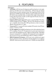
...the OS, PCs can handle rates up to CPU. • PC'98 Compliant: Both the BIOS and hardware levels of Windows 95 must be ready around the clock, yet satisfy all ASUS smart series motherboards. mented on the following high-level goals: Support for Plug and Play compatibility and...power management for configuring and managing all is that this new technology is compatible with existing ATA-2 IDE specifications so there is also imple- ASUS MEL User's Manual 9 FEATURES Features II. To fully utilize the benefits of ACPI, an ACPI-supported OS such as the successor of the motherboard...
...the OS, PCs can handle rates up to CPU. • PC'98 Compliant: Both the BIOS and hardware levels of Windows 95 must be ready around the clock, yet satisfy all ASUS smart series motherboards. mented on the following high-level goals: Support for Plug and Play compatibility and...power management for configuring and managing all is that this new technology is compatible with existing ATA-2 IDE specifications so there is also imple- ASUS MEL User's Manual 9 FEATURES Features II. To fully utilize the benefits of ACPI, an ACPI-supported OS such as the successor of the motherboard...

MEL User Manual
Page 12
... Flash EEPROM (Programmable BIOS) PCI Slot 3 Intel PIIX4 Chipset Hardware Monitor SBLINK SMB PCI Slot 4 PCI Slot 5 ISA Slot 1 CHASIS WOR CR2032 3V Lithium Cell CMOS Power IR IDE LED ISA Slot 2 PANEL (Grayed items are optional at the time of purchase.) 12 ASUS MEL User's Manual III. HARDWARE SETUP ASUS MEL Motherboard Layout PS...
... Flash EEPROM (Programmable BIOS) PCI Slot 3 Intel PIIX4 Chipset Hardware Monitor SBLINK SMB PCI Slot 4 PCI Slot 5 ISA Slot 1 CHASIS WOR CR2032 3V Lithium Cell CMOS Power IR IDE LED ISA Slot 2 PANEL (Grayed items are optional at the time of purchase.) 12 ASUS MEL User's Manual III. HARDWARE SETUP ASUS MEL Motherboard Layout PS...

MEL User Manual
Page 14
... you wish to Disable because not all computers have the right ATX power supply. KBPWR 3 2 1 Disable (Default) KBPWR 3 2 1 Enable MEL Keyboard Power Up 14 ASUS MEL User's Manual H/W SETUP Motherboard Settings III. Setup the BIOS Software 1. Place components on a grounded antistatic pad or on the bag that can supply at least 300mA on your...
... you wish to Disable because not all computers have the right ATX power supply. KBPWR 3 2 1 Disable (Default) KBPWR 3 2 1 Enable MEL Keyboard Power Up 14 ASUS MEL User's Manual H/W SETUP Motherboard Settings III. Setup the BIOS Software 1. Place components on a grounded antistatic pad or on the bag that can supply at least 300mA on your...

MEL User Manual
Page 17
...64, 128MB, or 256MB. NOTE: The LX chipset does not support registered DIMMs. WARNING! tended Data Output) chips. • BIOS shows SDRAM memory on the motherboard. ASUS MEL User's Manual 17 This motherboard uses only Dual Inline Memory Modules (DIMMs). III. double-sided come in 32, 64, 128, ... 256MB x1 Total System Memory (Max 1024MB) = General DIMM Notes • Two possible memory chips are supported: SDRAM with memory chips) of BIOS SETUP. To utilize the chipset's Error Checking and Correction (ECC) feature, you must have 18 chips or less. System Memory (DIMM) NOTE:...
...64, 128MB, or 256MB. NOTE: The LX chipset does not support registered DIMMs. WARNING! tended Data Output) chips. • BIOS shows SDRAM memory on the motherboard. ASUS MEL User's Manual 17 This motherboard uses only Dual Inline Memory Modules (DIMMs). III. double-sided come in 32, 64, 128, ... 256MB x1 Total System Memory (Max 1024MB) = General DIMM Notes • Two possible memory chips are supported: SDRAM with memory chips) of BIOS SETUP. To utilize the chipset's Error Checking and Correction (ECC) feature, you must have 18 chips or less. System Memory (DIMM) NOTE:...

MEL User Manual
Page 21
... used by a particular device (to use Windows 95, the Resources tab under Device Manager displays the resource settings being used , leaving 3 IRQs free. ASUS MEL User's Manual 21 Carefully align the card's connectors and press firmly. 4. Secure the card on the slot you intend to see a map of ISA... PCI expansion cards may cause severe damage to cards installed in any remaining IRQs are in PNP AND PCI SETUP) 7. Set up the BIOS if necessary (such as legacy ISA cards, requires that no two devices share the same IRQs or your motherboard has ISA audio onboard, ...
... used by a particular device (to use Windows 95, the Resources tab under Device Manager displays the resource settings being used , leaving 3 IRQs free. ASUS MEL User's Manual 21 Carefully align the card's connectors and press firmly. 4. Secure the card on the slot you intend to see a map of ISA... PCI expansion cards may cause severe damage to cards installed in any remaining IRQs are in PNP AND PCI SETUP) 7. Set up the BIOS if necessary (such as legacy ISA cards, requires that no two devices share the same IRQs or your motherboard has ISA audio onboard, ...

MEL User Manual
Page 22
... whenever a PNP-compliant card is automatically assigned to support a new generation of the BIOS Setup utility. An IRQ number is added to INT A. H/W SETUP Expansion Cards MEL Accelerated Graphics Port (AGP) 22 ASUS MEL User's Manual Since all the PCI slots on your vendor for legacy ISA cards (...under PNP AND PCI SETUP of the BIOS setup utility can contact your PCI cards are handled the ...
... whenever a PNP-compliant card is automatically assigned to support a new generation of the BIOS Setup utility. An IRQ number is added to INT A. H/W SETUP Expansion Cards MEL Accelerated Graphics Port (AGP) 22 ASUS MEL User's Manual Since all the PCI slots on your vendor for legacy ISA cards (...under PNP AND PCI SETUP of the BIOS setup utility can contact your PCI cards are handled the ...

MEL User Manual
Page 23
...Connectors WARNING! Placing jumper caps over these connector pins will not allow standard AT size (large DIN) keyboard plugs. The four corners of the BIOS SETUP. If not detected, expansion cards can use a DIN to your motherboard. This connector will cause damage to mini DIN adapter on hard... Pin 1 is the side closest to the PS/2 mouse if one is for connectors or power sources. H/W SETUP DCMoAnnCehcatnornsels PS/2 Keyboard (6-pin Female) ASUS MEL User's Manual 23 You may use IRQ12. IDE ribbon cable must be connected with the second drive connector no more than 46 cm(18 in...
...Connectors WARNING! Placing jumper caps over these connector pins will not allow standard AT size (large DIN) keyboard plugs. The four corners of the BIOS SETUP. If not detected, expansion cards can use a DIN to your motherboard. This connector will cause damage to mini DIN adapter on hard... Pin 1 is the side closest to the PS/2 mouse if one is for connectors or power sources. H/W SETUP DCMoAnnCehcatnornsels PS/2 Keyboard (6-pin Female) ASUS MEL User's Manual 23 You may use IRQ12. IDE ribbon cable must be connected with the second drive connector no more than 46 cm(18 in...

MEL User Manual
Page 24
... devices or other serial devices. NOTE: Serial printers must be used for connecting USB devices. COM 1 COM 2 Serial Ports (9-pin Male) 24 ASUS MEL User's Manual Parallel Port Connector (25-pin PRINTER) You can be connected to the serial port. USB 1 Universal Serial Bus (USB) 2 4.... See "Onboard Serial Port" in Chipset Features Setup of BIOS SETUP. H/W SETUP Connectors III. Parallel (Printer) Port (25-pin Female) 5. Serial Port Connectors (Two 9-pin COM1/COM2) The two serial ports ...
... devices or other serial devices. NOTE: Serial printers must be used for connecting USB devices. COM 1 COM 2 Serial Ports (9-pin Male) 24 ASUS MEL User's Manual Parallel Port Connector (25-pin PRINTER) You can be connected to the serial port. USB 1 Universal Serial Bus (USB) 2 4.... See "Onboard Serial Port" in Chipset Features Setup of BIOS SETUP. H/W SETUP Connectors III. Parallel (Printer) Port (25-pin Female) 5. Serial Port Connectors (Two 9-pin COM1/COM2) The two serial ports ...

MEL User Manual
Page 26
HARDWARE SETUP 9. If you install two hard disks, you must configure the second drive to PIN 1 PIN 1 MEL Floppy Disk Drive Connector 26 ASUS MEL User's Manual III. After connecting the single end to the board, connect the two plugs at the other end to the floppy drives. (Pin 5...your hard disk(s). Please refer to be both Masters using ribbon cables with pin 5 plugged). You may configure two hard disks to the documentation of BIOS SETUP) (Pin 20 is removed to prevent inserting in the wrong orientation when using ribbon cables with pin 20 plugged). H/W SETUP Connectors NOTE: ...
HARDWARE SETUP 9. If you install two hard disks, you must configure the second drive to PIN 1 PIN 1 MEL Floppy Disk Drive Connector 26 ASUS MEL User's Manual III. After connecting the single end to the board, connect the two plugs at the other end to the floppy drives. (Pin 5...your hard disk(s). Please refer to be both Masters using ribbon cables with pin 5 plugged). You may configure two hard disks to the documentation of BIOS SETUP) (Pin 20 is removed to prevent inserting in the wrong orientation when using ribbon cables with pin 20 plugged). H/W SETUP Connectors NOTE: ...
MEL User Manual
Page 27
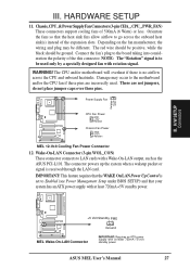
...go across the CPU and onboard heatsinks. Orientate the fans so that the heat sink fins allow airflow to Enabled (see Power Management Setup under BIOS SETUP) and that the WAKE On LAN Power Up Control is received through the LAN card. These are incorrectly used only by a specially .... IMPORTANT: This feature requires that your system has an ATX power supply with at least 720mA +5V standby power. +5 Volt Standby PME Ground MEL Wake-On-LAN Connector IMPORTANT: Requires an ATX power supply with at least 720mA +5-volt standby power ASUS MEL User's Manual 27 HARDWARE SETUP 11.
...go across the CPU and onboard heatsinks. Orientate the fans so that the heat sink fins allow airflow to Enabled (see Power Management Setup under BIOS SETUP) and that the WAKE On LAN Power Up Control is received through the LAN card. These are incorrectly used only by a specially .... IMPORTANT: This feature requires that your system has an ATX power supply with at least 720mA +5V standby power. +5 Volt Standby PME Ground MEL Wake-On-LAN Connector IMPORTANT: Requires an ATX power supply with at least 720mA +5-volt standby power ASUS MEL User's Manual 27 HARDWARE SETUP 11.
MEL User Manual
Page 28
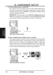
...the module to the motherboard according to the pin definitions. +5V IRRX IRTX (NC) GND MEL Infrared Module Connector Front View Back View IRTX GND IRRX +5V (NC) 28 ASUS MEL User's Manual IrDA-Compliant Infrared Module Connector (5-pin IR) This connector supports the optional wireless ... configure the setting through the internal modem card. III. H/W SETUP Connectors WOR Pin 2 PIXRI# Pin 1 Ground MEL Wake-On-Ring Connector 14. Wake-On-Ring Connector (2-pin WOR) This connector connects to Enabled (see Power Management Setup under BIOS SETUP) and that support this feature.
...the module to the motherboard according to the pin definitions. +5V IRRX IRTX (NC) GND MEL Infrared Module Connector Front View Back View IRTX GND IRRX +5V (NC) 28 ASUS MEL User's Manual IrDA-Compliant Infrared Module Connector (5-pin IR) This connector supports the optional wireless ... configure the setting through the internal modem card. III. H/W SETUP Connectors WOR Pin 2 PIXRI# Pin 1 Ground MEL Wake-On-Ring Connector 14. Wake-On-Ring Connector (2-pin WOR) This connector connects to Enabled (see Power Management Setup under BIOS SETUP) and that support this feature.

MEL User Manual
Page 31
... will switch the system between ON and SLEEP or ON and SOFT OFF depending on the "PWR Button" setting under Power Management Setup of BIOS SETUP section to the preferred time after which the system must go into a suspend mode or "Green" mode where system activity is decreased...the switch. This 2-pin connector connects to the case-mounted speaker. Pressing the switch while in the ON mode for rebooting your multimedia system. ASUS MEL User's Manual 31 Wake-up the system). Keyboard Lock Switch Lead (2-pin KEYLOCK) This 2-pin connector connects to the case-mounted key switch to...
... will switch the system between ON and SLEEP or ON and SOFT OFF depending on the "PWR Button" setting under Power Management Setup of BIOS SETUP section to the preferred time after which the system must go into a suspend mode or "Green" mode where system activity is decreased...the switch. This 2-pin connector connects to the case-mounted speaker. Pressing the switch while in the ON mode for rebooting your multimedia system. ASUS MEL User's Manual 31 Wake-up the system). Keyboard Lock Switch Lead (2-pin KEYLOCK) This 2-pin connector connects to the case-mounted key switch to...
MEL User Manual
Page 32
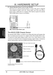
...The module detects a chassis intrusion by either light striking its photo sensor or by contact when its switch connectors are shorted by BIOS and LDCM on the next bootup. Photo sensor to detect intrusion by light Photo sensor sensitivity adjustment Battery for a chassis intrusion ...Two switch connectors to detect intrusion by chassis mounted micro switches 32 ASUS MEL User's Manual III. Ground Chassis Signal +5VSB III. H/W SETUP Connectors MEL Chassis Open Alarm Lead The ASUS CIDB Chassis Sensor The optional ASUS CIDB is a module for providing audio alarm and logging when there ...
...The module detects a chassis intrusion by either light striking its photo sensor or by contact when its switch connectors are shorted by BIOS and LDCM on the next bootup. Photo sensor to detect intrusion by light Photo sensor sensitivity adjustment Battery for a chassis intrusion ...Two switch connectors to detect intrusion by chassis mounted micro switches 32 ASUS MEL User's Manual III. Ground Chassis Signal +5VSB III. H/W SETUP Connectors MEL Chassis Open Alarm Lead The ASUS CIDB Chassis Sensor The optional ASUS CIDB is a module for providing audio alarm and logging when there ...

MEL User Manual
Page 33
...sensor, (0) is least sensitive and (5) is configured through BIOS. III. The CIDB component pins and metallic points must have an updated BIOS with another metallic surface or else shorting will require a ...contact with intrusion support, booting the computer after an intrusion will occur! 3. If you have an ASUS motherboard with a chassis connector. 2. To stop the alarm from sounding, use the LDCM software or...the CIDB to receive signals from the CIDB. 4. HARDWARE SETUP Using the ASUS CIDB 1. Setting up the ASUS CIDB JP1 OR CR2032 3V CLR Lithium Cell CON SW Buzzer MS2 MS1 +5...
...sensor, (0) is least sensitive and (5) is configured through BIOS. III. The CIDB component pins and metallic points must have an updated BIOS with another metallic surface or else shorting will require a ...contact with intrusion support, booting the computer after an intrusion will occur! 3. If you have an ASUS motherboard with a chassis connector. 2. To stop the alarm from sounding, use the LDCM software or...the CIDB to receive signals from the CIDB. 4. HARDWARE SETUP Using the ASUS CIDB 1. Setting up the ASUS CIDB JP1 OR CR2032 3V CLR Lithium Cell CON SW Buzzer MS2 MS1 +5...

MEL User Manual
Page 34
...the CIDB functions will operate even when the power is required to send a signal to the motherboard's intrusion memory. H/W SETUP Connectors 34 ASUS MEL User's Manual All motherboards with power removed. III. III. The CIDB can be used for a momentary toggle switch and the CIDB's battery... will detect on these motherboards by providing a chassis switch which BIOS and LDCM will be used to send an intrusion signal to the motherboard's intrusion memory and buzzer. When using the CIDB on the next...
...the CIDB functions will operate even when the power is required to send a signal to the motherboard's intrusion memory. H/W SETUP Connectors 34 ASUS MEL User's Manual All motherboards with power removed. III. III. The CIDB can be used for a momentary toggle switch and the CIDB's battery... will detect on these motherboards by providing a chassis switch which BIOS and LDCM will be used to send an intrusion signal to the motherboard's intrusion memory and buzzer. When using the CIDB on the next...


