MEL-M User Manual
Page 2
... ONLY, AND ARE SUBJECT TO CHANGE AT ANY TIME WITHOUT NOTICE, AND SHOULD NOT BE CONSTRUED AS A COMMITMENT BY ASUS. Product Name: ASUS MEL-M Manual Revision: 1.03 E329 Release Date: February 1999 2 ASUS MEL-M User's Manual ASUS ASSUMES NO RESPONSIBILITY OR LIABILITY FOR ANY ERRORS OR INACCURACIES THAT MAY APPEAR IN THIS MANUAL, INCLUDING THE PRODUCTS...
... ONLY, AND ARE SUBJECT TO CHANGE AT ANY TIME WITHOUT NOTICE, AND SHOULD NOT BE CONSTRUED AS A COMMITMENT BY ASUS. Product Name: ASUS MEL-M Manual Revision: 1.03 E329 Release Date: February 1999 2 ASUS MEL-M User's Manual ASUS ASSUMES NO RESPONSIBILITY OR LIABILITY FOR ANY ERRORS OR INACCURACIES THAT MAY APPEAR IN THIS MANUAL, INCLUDING THE PRODUCTS...
MEL-M User Manual
Page 3
... +886-2-2894-3447 ext. 701 Fax: +886-2-2895-9254 Email: tsd@asus.com.tw Newsgroup: news2.asus.com.tw WWW: www.asus.com.tw FTP: ftp.asus.com.tw/pub/ASUS ASUS COMPUTER INTERNATIONAL (America) Marketing Address: 6737 Mowry Avenue, Mowry Business Center, ...ASUS ASUS COMPUTER GmbH (Europe) Marketing Address: Harkort Str. 25, 40880 Ratingen, BRD, Germany Telephone: 49-2102-445011 Fax: 49-2102-442066 Email: [email protected] Technical Support Hotline: 49-2102-499712 BBS: 49-2102-448690 Email: [email protected] WWW: www.asuscom.de FTP: ftp.asuscom.de/pub/ASUSCOM ASUS MEL...
... +886-2-2894-3447 ext. 701 Fax: +886-2-2895-9254 Email: tsd@asus.com.tw Newsgroup: news2.asus.com.tw WWW: www.asus.com.tw FTP: ftp.asus.com.tw/pub/ASUS ASUS COMPUTER INTERNATIONAL (America) Marketing Address: 6737 Mowry Avenue, Mowry Business Center, ...ASUS ASUS COMPUTER GmbH (Europe) Marketing Address: Harkort Str. 25, 40880 Ratingen, BRD, Germany Telephone: 49-2102-445011 Fax: 49-2102-442066 Email: [email protected] Technical Support Hotline: 49-2102-499712 BBS: 49-2102-448690 Email: [email protected] WWW: www.asuscom.de FTP: ftp.asuscom.de/pub/ASUSCOM ASUS MEL...
MEL-M User Manual
Page 4
... 6. System Memory (DIMM 17 DIMM Memory Installation 18 3. INTRODUCTION 7 How this manual is organized 7 Item Checklist 7 II. FEATURES 8 The ASUS MEL-M Motherboard 8 Parts of PNP and PCI Setup 50 Load BIOS Defaults 52 Load Setup Defaults 52 Supervisor Password and User Password 53 IDE HDD Auto...Assigning IRQs for Expansion Cards 21 Assigning DMA Channels for ISA Cards 22 ISA Cards and Hardware Monitor 22 5. HARDWARE SETUP 12 ASUS MEL-M Motherboard Layout 12 Hardware Setup Steps 14 1. BIOS Setup 37 Load Defaults 38 Standard CMOS Setup 38 Details of Standard CMOS Setup...
... 6. System Memory (DIMM 17 DIMM Memory Installation 18 3. INTRODUCTION 7 How this manual is organized 7 Item Checklist 7 II. FEATURES 8 The ASUS MEL-M Motherboard 8 Parts of PNP and PCI Setup 50 Load BIOS Defaults 52 Load Setup Defaults 52 Supervisor Password and User Password 53 IDE HDD Auto...Assigning IRQs for Expansion Cards 21 Assigning DMA Channels for ISA Cards 22 ISA Cards and Hardware Monitor 22 5. HARDWARE SETUP 12 ASUS MEL-M Motherboard Layout 12 Hardware Setup Steps 14 1. BIOS Setup 37 Load Defaults 38 Standard CMOS Setup 38 Details of Standard CMOS Setup...
MEL-M User Manual
Page 5
Yamaha XGstudio 69 D. Ystation 75 APPENDIX 83 DMI Utility 83 ASUS CIDB Chassis Intrusion Sensor Module 87 ASUS PCI-L101 Fast Ethernet Card 89 ASUS MEL-M User's Manual 5 Audio Driver 67 C. CONTENTS Save & Exit Setup 55 Exit Without Saving 55 V. PC Probe 61 B. SUPPORT CD 57 A.
Yamaha XGstudio 69 D. Ystation 75 APPENDIX 83 DMI Utility 83 ASUS CIDB Chassis Intrusion Sensor Module 87 ASUS PCI-L101 Fast Ethernet Card 89 ASUS MEL-M User's Manual 5 Audio Driver 67 C. CONTENTS Save & Exit Setup 55 Exit Without Saving 55 V. PC Probe 61 B. SUPPORT CD 57 A.
MEL-M User Manual
Page 6
... equipment. Canadian Department of Communications Statement This digital apparatus does not exceed the Class B limits for a Class B digital device, pursuant to Part 15 of Communications. 6 ASUS MEL-M User's Manual This equipment has been tested and found to comply with FCC Rules Part 15. FCC & DOC COMPLIANCE Federal Communications Commission Statement This device...
... equipment. Canadian Department of Communications Statement This digital apparatus does not exceed the Class B limits for a Class B digital device, pursuant to Part 15 of Communications. 6 ASUS MEL-M User's Manual This equipment has been tested and found to comply with FCC Rules Part 15. FCC & DOC COMPLIANCE Federal Communications Commission Statement This device...

MEL-M User Manual
Page 7
... of spare jumper caps (1) Support CD with drivers and utilities (1) This Motherboard User's Manual ASUS IrDA-compliant infrared module (optional) ASUS chassis intrusion sensor module (optional) ASUS PCI-L101 Wake-On-LAN 10/100 fast ethernet card (optional) ASUS MEL-M User's Manual 7 INTRODUCTION How this product III. Software Setup Information on setting up the motherboard...
... of spare jumper caps (1) Support CD with drivers and utilities (1) This Motherboard User's Manual ASUS IrDA-compliant infrared module (optional) ASUS chassis intrusion sensor module (optional) ASUS PCI-L101 Wake-On-LAN 10/100 fast ethernet card (optional) ASUS MEL-M User's Manual 7 INTRODUCTION How this product III. Software Setup Information on setting up the motherboard...
MEL-M User Manual
Page 8
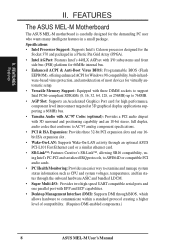
II. FEATURES Features II. FEATURES The ASUS MEL-M Motherboard The ASUS MEL-M motherboard is carefully designed for high performance, component level interconnect targeted at 3D graphical display applications supporting a 66MHz bus. &#...(DMI): Supports DMI through BIOS, which allows hardware to communicate within a standard protocol creating a higher level of compatibility. (Requires DMI-enabled components.) 8 ASUS MEL-M User's Manual Specifications • Intel Processor Support: Supports Intel's Celeron processor designed for the Socket 370 and packaged in a Plastic Pin Grid Array (...
II. FEATURES Features II. FEATURES The ASUS MEL-M Motherboard The ASUS MEL-M motherboard is carefully designed for high performance, component level interconnect targeted at 3D graphical display applications supporting a 66MHz bus. &#...(DMI): Supports DMI through BIOS, which allows hardware to communicate within a standard protocol creating a higher level of compatibility. (Requires DMI-enabled components.) 8 ASUS MEL-M User's Manual Specifications • Intel Processor Support: Supports Intel's Celeron processor designed for the Socket 370 and packaged in a Plastic Pin Grid Array (...

MEL-M User Manual
Page 9
... to 528MB/s max using UltraDMA/33 Bus Master IDE can be ready around the clock, yet satisfy all ASUS smart series of Windows 95 must be used. • Double the IDE Transfer Speed: IDE transfers using ...sec. FEATURES Features II. ACPI provides more Energy Saving Features for Windows 95/98/NT.• SDRAM Optimized Performance: ASUS smart series motherboards support the new generation memory, Synchronous Dynamic Random Access Memory (SDRAM), which increases the data transfer rate... and power management for configuring and managing all is also imple- ASUS MEL-M User's Manual 9 II.
... to 528MB/s max using UltraDMA/33 Bus Master IDE can be ready around the clock, yet satisfy all ASUS smart series of Windows 95 must be used. • Double the IDE Transfer Speed: IDE transfers using ...sec. FEATURES Features II. ACPI provides more Energy Saving Features for Windows 95/98/NT.• SDRAM Optimized Performance: ASUS smart series motherboards support the new generation memory, Synchronous Dynamic Random Access Memory (SDRAM), which increases the data transfer rate... and power management for configuring and managing all is also imple- ASUS MEL-M User's Manual 9 II.
MEL-M User Manual
Page 10
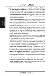
... critical for more than 4 seconds places the system into Sleep mode. The system resource monitor will give the user information on remotely through an optional ASUS CIDB module and Intel LDCM. 10 ASUS MEL-M User's Manual II.
... critical for more than 4 seconds places the system into Sleep mode. The system resource monitor will give the user information on remotely through an optional ASUS CIDB module and Intel LDCM. 10 ASUS MEL-M User's Manual II.
MEL-M User Manual
Page 11
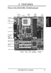
FEATURES Parts of the ASUS MEL-M Motherboard T: PS/2 Mouse B: PS/2 Keyboard T: USB 1 B: USB 2 B: COM 1 T: Parallel/Printer B: COM 2 T: Joystick/Midi B: Out/In/Mic (optional) Yamaha Audio (optional) AGP Port 3 PCI Slots Audio Codec (optional) Multi-I/O Chip 1 ISA Slot ATX Power Connector Socket 370 Intel 440LX AGPset 3 DIMM Sockets DIP Switches Wake-On-LAN SB-LinkTM Intel PIIX4 Programmable Hardware Monitor Connector Connector PCIset Flash EEPROM (optional) ASUS MEL-M User's Manual 11 FEATURES Motherboard Parts II. II.
FEATURES Parts of the ASUS MEL-M Motherboard T: PS/2 Mouse B: PS/2 Keyboard T: USB 1 B: USB 2 B: COM 1 T: Parallel/Printer B: COM 2 T: Joystick/Midi B: Out/In/Mic (optional) Yamaha Audio (optional) AGP Port 3 PCI Slots Audio Codec (optional) Multi-I/O Chip 1 ISA Slot ATX Power Connector Socket 370 Intel 440LX AGPset 3 DIMM Sockets DIP Switches Wake-On-LAN SB-LinkTM Intel PIIX4 Programmable Hardware Monitor Connector Connector PCIset Flash EEPROM (optional) ASUS MEL-M User's Manual 11 FEATURES Motherboard Parts II. II.
MEL-M User Manual
Page 12
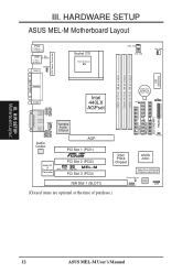
H/W SETUP Motherboard Layout III. HARDWARE SETUP ASUS MEL-M Motherboard Layout PS/2 T: Mouse B: Keyboard USB T: Port 1 B: Port 2 T: Top B: Bottom COM1 KBPWR Socket 370 Thermal Sensor 01 01 01 PWR_FAN CPU_FAN CHA_FAN PARALLEL PORT ATX...Yamaha Audio Chipset In Mic Audio Codec AGP PCI Slot 1 (PCI1) R Multi-I/O & Keyboard Controller PCI Slot 2 (PCI2) MEL-M WOL_CON SBLINK PCI Slot 3 (PCI3) ISA Slot 1 (SLOT1) 01 23 45 IDELED Intel PIIX4 Chipset ASUS ASIC 2Mbit Flash EEPROM (Programmable BIOS) Thermal Sensor CHASIS Hardware Monitor SMB (Grayed items are optional at the...
H/W SETUP Motherboard Layout III. HARDWARE SETUP ASUS MEL-M Motherboard Layout PS/2 T: Mouse B: Keyboard USB T: Port 1 B: Port 2 T: Top B: Bottom COM1 KBPWR Socket 370 Thermal Sensor 01 01 01 PWR_FAN CPU_FAN CHA_FAN PARALLEL PORT ATX...Yamaha Audio Chipset In Mic Audio Codec AGP PCI Slot 1 (PCI1) R Multi-I/O & Keyboard Controller PCI Slot 2 (PCI2) MEL-M WOL_CON SBLINK PCI Slot 3 (PCI3) ISA Slot 1 (SLOT1) 01 23 45 IDELED Intel PIIX4 Chipset ASUS ASIC 2Mbit Flash EEPROM (Programmable BIOS) Thermal Sensor CHASIS Hardware Monitor SMB (Grayed items are optional at the...

MEL-M User Manual
Page 13
H/W SETUP Layout Contents III. ASUS MEL-M User's Manual 13 III. otherwise, conflicts will occur. HARDWARE SETUP Motherboard Settings 1) KBPWR 2) DIP-Switch 5 3) DIP-Switch 6 4) DIP-Switch 1,2,3,4 5) DIP-Switch 7,8,9,10 p. 14 Keyboard Power ...
H/W SETUP Layout Contents III. ASUS MEL-M User's Manual 13 III. otherwise, conflicts will occur. HARDWARE SETUP Motherboard Settings 1) KBPWR 2) DIP-Switch 5 3) DIP-Switch 6 4) DIP-Switch 1,2,3,4 5) DIP-Switch 7,8,9,10 p. 14 Keyboard Power ...

MEL-M User Manual
Page 14
... the components are separated from static electricity, you should follow some precautions whenever you do not have the right ATX power supply. 01 01 01 R MEL-M MEL-M Keyboard Power Up KBPWR 3 2 1 Disable (Default) KBPWR 3 2 1 Enable 14 ASUS MEL-M User's Manual
... the components are separated from static electricity, you should follow some precautions whenever you do not have the right ATX power supply. 01 01 01 R MEL-M MEL-M Keyboard Power Up KBPWR 3 2 1 Disable (Default) KBPWR 3 2 1 Enable 14 ASUS MEL-M User's Manual

MEL-M User Manual
Page 15
III. R MEL-M MEL-M DIP Switches 01 01 01 ON 1 2 3 4 5 6 7 8 9 10 OFF ON The example below shows all the switches in the OFF position. HARDWARE SETUP Motherboard Settings (DIP Switches) Some of the motherboard's onboard functions can be adjusted through the DIP switches. The white block represents the switch's position.
III. R MEL-M MEL-M DIP Switches 01 01 01 ON 1 2 3 4 5 6 7 8 9 10 OFF ON The example below shows all the switches in the OFF position. HARDWARE SETUP Motherboard Settings (DIP Switches) Some of the motherboard's onboard functions can be adjusted through the DIP switches. The white block represents the switch's position.
MEL-M User Manual
Page 16
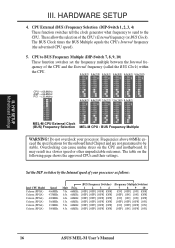
...4 5 6 7 8 9 10 ON 1 2 3 4 5 6 7 8 9 10 ON 1 2 3 4 5 6 7 8 9 10 ON 1 2 3 4 5 6 7 8 9 10 ON 1 2 3 4 5 6 7 8 9 10 ON 1 2 3 4 5 6 7 8 9 10 MEL-M CPU External Clock (BUS) Frequency Selection MEL-M CPU : BUS Frequency Multiple WARNING! quency of the CPU's External frequency (or BUS Clock). Do not overclock your processor as follows: Intel...ON] [OFF] [OFF] [ON] 4.5x 66MHz [OFF] [OFF] [OFF] [OFF] [OFF] [ON] [OFF] [ON] 16 ASUS MEL-M User's Manual Overclocking can cause undue stress on the following page shows the approved CPUs and their settings. HARDWARE SETUP 4. The table on the CPU...
...4 5 6 7 8 9 10 ON 1 2 3 4 5 6 7 8 9 10 ON 1 2 3 4 5 6 7 8 9 10 ON 1 2 3 4 5 6 7 8 9 10 ON 1 2 3 4 5 6 7 8 9 10 ON 1 2 3 4 5 6 7 8 9 10 MEL-M CPU External Clock (BUS) Frequency Selection MEL-M CPU : BUS Frequency Multiple WARNING! quency of the CPU's External frequency (or BUS Clock). Do not overclock your processor as follows: Intel...ON] [OFF] [OFF] [ON] 4.5x 66MHz [OFF] [OFF] [OFF] [OFF] [OFF] [ON] [OFF] [ON] 16 ASUS MEL-M User's Manual Overclocking can cause undue stress on the following page shows the approved CPUs and their settings. HARDWARE SETUP 4. The table on the CPU...
MEL-M User Manual
Page 17
... more than EDO chips. • BIOS shows SDRAM memory on the motherboard. Memory modules must use a DIMM module with memory chips) of BIOS SETUP. III. ASUS MEL-M User's Manual 17 IMPORTANT: Memory speed setup is required through "Auto Configuration" in 32, 64, 128, 256MB. HARDWARE SETUP 2. Memory modules with this mother- H/W SETUP...
... more than EDO chips. • BIOS shows SDRAM memory on the motherboard. Memory modules must use a DIMM module with memory chips) of BIOS SETUP. III. ASUS MEL-M User's Manual 17 IMPORTANT: Memory speed setup is required through "Auto Configuration" in 32, 64, 128, 256MB. HARDWARE SETUP 2. Memory modules with this mother- H/W SETUP...
MEL-M User Manual
Page 18
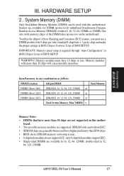
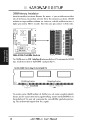
This motherboard supports four clock signals. 18 ASUS MEL-M User's Manual HARDWARE SETUP DIMM Memory Installation Insert the module(s) as shown. H/W SETUP System Memory R MEL-M MEL-M 168-Pin DIMM Sockets The DIMMs must ask your retailer the correct DIMM type before purchasing. SIMM modules have the same pin contact on the ...
This motherboard supports four clock signals. 18 ASUS MEL-M User's Manual HARDWARE SETUP DIMM Memory Installation Insert the module(s) as shown. H/W SETUP System Memory R MEL-M MEL-M 168-Pin DIMM Sockets The DIMMs must ask your retailer the correct DIMM type before purchasing. SIMM modules have the same pin contact on the ...
MEL-M User Manual
Page 19
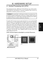
... weight of the lever. NOTE: Set the bus frequency and multiple for reference only; Socket 370 CPU (Top) Socket 370 CPU (Bottom) 01 01 01 R MEL-M MEL-M Socket 370 Notch ASUS MEL-M User's Manual 19
... weight of the lever. NOTE: Set the bus frequency and multiple for reference only; Socket 370 CPU (Top) Socket 370 CPU (Bottom) 01 01 01 R MEL-M MEL-M Socket 370 Notch ASUS MEL-M User's Manual 19
MEL-M User Manual
Page 20
H/W SETUP CPU 20 ASUS MEL-M User's Manual HARDWARE SETUP (This page was intentionally left blank.) III. III.
H/W SETUP CPU 20 ASUS MEL-M User's Manual HARDWARE SETUP (This page was intentionally left blank.) III. III.

MEL-M User Manual
Page 21
... then install it in use the Microsoft Diagnostics (MSD.EXE) utility located in PNP AND PCI SETUP) 7. You may cause severe damage to as jumpers. 2. ASUS MEL-M User's Manual 21 If your power supply when adding or removing expansion cards or other system components. NOTE: The onboard audio by a particular device (to...
... then install it in use the Microsoft Diagnostics (MSD.EXE) utility located in PNP AND PCI SETUP) 7. You may cause severe damage to as jumpers. 2. ASUS MEL-M User's Manual 21 If your power supply when adding or removing expansion cards or other system components. NOTE: The onboard audio by a particular device (to...


