MAXIMUS V FORMULA User's Manual
Page 5
... 4.3.6 USB 3.0 Boost 4-16 4.3.7 Ai Charger 4-17 4.3.8 USB Charger 4-18 4.3.9 Probe II 4-20 4.3.10 Sensor Recorder 4-21 4.3.11 ASUS Update 4-23 4.3.12 MyLogo2 4-24 4.3.13 Audio configurations 4-25 4.3.14 ROG Connect 4-28 4.3.15 GameFirst II 4-30 4.3.16 MemTweakIt 4-32 ...Chapter 5: RAID support 5-1 5.1 RAID configurations 5-1 5.1.1 RAID definitions 5-1 5.1.2 Installing Serial ATA hard disks 5-2 5.1.3 Setting the RAID item in BIOS 5-2 5.1.4 Intel® Rapid Storage Technology Option ROM utility 5-3 5.2 Creating a RAID driver disk 5-8 5.2.1...
... 4.3.6 USB 3.0 Boost 4-16 4.3.7 Ai Charger 4-17 4.3.8 USB Charger 4-18 4.3.9 Probe II 4-20 4.3.10 Sensor Recorder 4-21 4.3.11 ASUS Update 4-23 4.3.12 MyLogo2 4-24 4.3.13 Audio configurations 4-25 4.3.14 ROG Connect 4-28 4.3.15 GameFirst II 4-30 4.3.16 MemTweakIt 4-32 ...Chapter 5: RAID support 5-1 5.1 RAID configurations 5-1 5.1.1 RAID definitions 5-1 5.1.2 Installing Serial ATA hard disks 5-2 5.1.3 Setting the RAID item in BIOS 5-2 5.1.4 Intel® Rapid Storage Technology Option ROM utility 5-3 5.2 Creating a RAID driver disk 5-8 5.2.1...
MAXIMUS V FORMULA User's Manual
Page 6
...6-6 6.2.3 Installing the device drivers 6-7 6.2.4 Enabling the NVIDIA® SLI™ technology 6-8 6.3 LucidLogix Virtu MVP 6-10 6.3.1 Installing LucidLogix Virtu MVP 6-10 6.3.2 Setting up your display 6-11 6.3.3 Configuring LucidLogix Virtu MVP 6-12 Chapter 7: Intel® technologies 7-1 7.1 Intel® 2012 Desktop responsiveness technologies 7-1 7.1.1 Intel® Smart... 360 8-8 8.2.4 Connecting to iPhone/ iPod/ iPad/ MP3 player 8-10 8.3 Driver Installation 8-11 8.4 ThunderFX Utility Introduction 8-12 Appendices A-1 Notices ...A-1 ASUS contact information A-5 vi
...6-6 6.2.3 Installing the device drivers 6-7 6.2.4 Enabling the NVIDIA® SLI™ technology 6-8 6.3 LucidLogix Virtu MVP 6-10 6.3.1 Installing LucidLogix Virtu MVP 6-10 6.3.2 Setting up your display 6-11 6.3.3 Configuring LucidLogix Virtu MVP 6-12 Chapter 7: Intel® technologies 7-1 7.1 Intel® 2012 Desktop responsiveness technologies 7-1 7.1.1 Intel® Smart... 360 8-8 8.2.4 Connecting to iPhone/ iPod/ iPad/ MP3 player 8-10 8.3 Driver Installation 8-11 8.4 ThunderFX Utility Introduction 8-12 Appendices A-1 Notices ...A-1 ASUS contact information A-5 vi

MAXIMUS V FORMULA User's Manual
Page 7
... the product, contact a qualified service technician or your retailer. Do not place the product in your local power company. • If the power supply is set to the correct voltage in any damage, contact your retailer. If possible, disconnect all power cables from connectors, slots, sockets and circuitry. • Avoid dust...
... the product, contact a qualified service technician or your retailer. Do not place the product in your local power company. • If the power supply is set to the correct voltage in any damage, contact your retailer. If possible, disconnect all power cables from connectors, slots, sockets and circuitry. • Avoid dust...
MAXIMUS V FORMULA User's Manual
Page 8
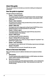
...to the following parts: • Chapter 1: Product introduction This chapter describes the features of the standard package. Refer to change system settings through the BIOS Setup menus. These documents are also provided. • Chapter 4: Software support This chapter describes the contents of ...the switches, jumpers, and connectors on ASUS hardware and software products. About this guide is organized This guide contains the following sources for additional information and for product and ...
...to the following parts: • Chapter 1: Product introduction This chapter describes the features of the standard package. Refer to change system settings through the BIOS Setup menus. These documents are also provided. • Chapter 4: Software support This chapter describes the contents of ...the switches, jumpers, and connectors on ASUS hardware and software products. About this guide is organized This guide contains the following sources for additional information and for product and ...
MAXIMUS V FORMULA User's Manual
Page 20
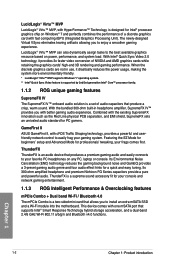
...console. ThunderFX is a supreme sound accessory fit for PC gamers. GameFirst II ASUS GameFirst II, with the existing SupremeFX innovation such as the Red Line physical PCB separation, and EMI shield, SupremeFX sets an unrivaled audio standard for your console and network gaming entertainment. 1.1.3 ROG..., performance, and system load. LucidLogix® Virtu™ MVP LucidLogix® Virtu™ MVP, with HyperFormance™ Technology, is a set of audio capacitors that produce a crisp, warm sound. LucidLogix® Virtu™ MVP can also dynamically assign tasks to install an extra ...
...console. ThunderFX is a supreme sound accessory fit for PC gamers. GameFirst II ASUS GameFirst II, with the existing SupremeFX innovation such as the Red Line physical PCB separation, and EMI shield, SupremeFX sets an unrivaled audio standard for your console and network gaming entertainment. 1.1.3 ROG..., performance, and system load. LucidLogix® Virtu™ MVP LucidLogix® Virtu™ MVP, with HyperFormance™ Technology, is a set of audio capacitors that produce a crisp, warm sound. LucidLogix® Virtu™ MVP can also dynamically assign tasks to install an extra ...
MAXIMUS V FORMULA User's Manual
Page 21
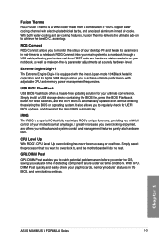
..., providing you with full control of your overclocking enjoyment, and offers you valuable time in real-time via a notebook. Chapter 1 ASUS MAXIMUS V FORMULA Series 1-3 It also allows you to monitor the status of your notebook, as well as make on your desktop PC and tweak ... FlashBack USB BIOS Flashback offers a hassle-free updating solution for your graphic cards, memory modules' statuses in the BIOS, and overclocking settings. DIMM Post, quickly and easily check your ultimate convenience. Fusion Thermo ROG Fusion Thermo is a VRM cooler made 10K Black Metallic capacitors...
..., providing you with full control of your overclocking enjoyment, and offers you valuable time in real-time via a notebook. Chapter 1 ASUS MAXIMUS V FORMULA Series 1-3 It also allows you to monitor the status of your notebook, as well as make on your desktop PC and tweak ... FlashBack USB BIOS Flashback offers a hassle-free updating solution for your graphic cards, memory modules' statuses in the BIOS, and overclocking settings. DIMM Post, quickly and easily check your ultimate convenience. Fusion Thermo ROG Fusion Thermo is a VRM cooler made 10K Black Metallic capacitors...
MAXIMUS V FORMULA User's Manual
Page 22
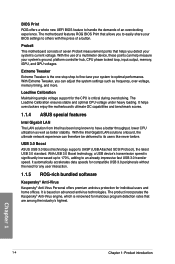
...impressive fast USB 3.0 transfer speed. With the Intel Gigabit LAN solutions onboard, the ultimate network experience can adjust the system settings such as better stability. It automatically accelerates data speeds for compatible USB 3.0 peripherals without the need for any user interaction...technologies. Chapter 1 1-4 Chapter 1: Product introduction It helps overclockers enjoy the motherboard's ultimate OC capabilities and benchmark scores. 1.1.4 ASUS special features Intel Gigabit LAN The LAN solution from Intel has been long known to have a better throughput, lower CPU ...
...impressive fast USB 3.0 transfer speed. With the Intel Gigabit LAN solutions onboard, the ultimate network experience can adjust the system settings such as better stability. It automatically accelerates data speeds for compatible USB 3.0 peripherals without the need for any user interaction...technologies. Chapter 1 1-4 Chapter 1: Product introduction It helps overclockers enjoy the motherboard's ultimate OC capabilities and benchmark scores. 1.1.4 ASUS special features Intel Gigabit LAN The LAN solution from Intel has been long known to have a better throughput, lower CPU ...
MAXIMUS V FORMULA User's Manual
Page 24
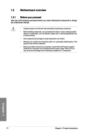
... components by the edges to the motherboard, peripherals, or components. 1.2 Motherboard overview 1.2.1 Before you proceed Take note of the following precautions before touching any motherboard settings. • Unplug the power cord from the power supply.
... components by the edges to the motherboard, peripherals, or components. 1.2 Motherboard overview 1.2.1 Before you proceed Take note of the following precautions before touching any motherboard settings. • Unplug the power cord from the power supply.
MAXIMUS V FORMULA User's Manual
Page 38
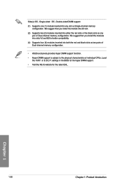
Single-sided DS - or D.O.C.P. settings in the BIOS for the hyper DIMM support. • Visit the ASUS website for better compatibility. (4) Supports four (4) modules inserted into any slot as two pairs of Dual-channel memory configuration. • ASUS exclusively provides hyper DIMM support function. • Hyper DIMM support is subject to the physical characteristics...
Single-sided DS - or D.O.C.P. settings in the BIOS for the hyper DIMM support. • Visit the ASUS website for better compatibility. (4) Supports four (4) modules inserted into any slot as two pairs of Dual-channel memory configuration. • ASUS exclusively provides hyper DIMM support function. • Hyper DIMM support is subject to the physical characteristics...

MAXIMUS V FORMULA User's Manual
Page 42
... performance when working on button that you to power up or wake up when the system is ideal for overclockers and gamers who continually change settings to enhance system performance. 1. This is plugged to reboot the system. Chapter 1 1-24 Chapter 1: Product introduction Power-on button The motherboard comes with a power-on...
... performance when working on button that you to power up or wake up when the system is ideal for overclockers and gamers who continually change settings to enhance system performance. 1. This is plugged to reboot the system. Chapter 1 1-24 Chapter 1: Product introduction Power-on button The motherboard comes with a power-on...
MAXIMUS V FORMULA User's Manual
Page 43
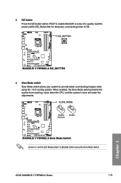
3. or press it to enable MemOK! GO button Press the GO button before using the -10oC cooling system. Slow Mode switch Slow Mode switch allows your system to provide better overclocking margins when using the Slow Mode Switch. When enabled, the Slow Mode switch prevents the system from crashing, slows down the CPU, and the system's tuner will make the adjustments. ASUS MAXIMUS V FORMULA Series 1-25 Chapter 1 Ensure to set the LN2 Mode jumper to [Enable] before POST to quickly load the preset profile (GO_Button file) for temporary overclocking when in OS. 4.
3. or press it to enable MemOK! GO button Press the GO button before using the -10oC cooling system. Slow Mode switch Slow Mode switch allows your system to provide better overclocking margins when using the Slow Mode Switch. When enabled, the Slow Mode switch prevents the system from crashing, slows down the CPU, and the system's tuner will make the adjustments. ASUS MAXIMUS V FORMULA Series 1-25 Chapter 1 Ensure to set the LN2 Mode jumper to [Enable] before POST to quickly load the preset profile (GO_Button file) for temporary overclocking when in OS. 4.
MAXIMUS V FORMULA User's Manual
Page 51
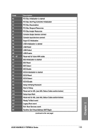
... below) Setup Input Wait Reserved for ASL (see ASL Status Codes section below) Ready To Boot event Legacy Boot event Exit Boot Services event Runtime Set Virtual Address MAP Begin (continued on the next page) Chapter 1 ASUS MAXIMUS V FORMULA Series 1-33
... below) Setup Input Wait Reserved for ASL (see ASL Status Codes section below) Ready To Boot event Legacy Boot event Exit Boot Services event Runtime Set Virtual Address MAP Begin (continued on the next page) Chapter 1 ASUS MAXIMUS V FORMULA Series 1-33
MAXIMUS V FORMULA User's Manual
Page 52
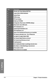
BF D0 D1 D2 D3 D4 D5 D6 D7 D8 D9 DA DB DC Description Runtime Set Virtual Address MAP End Legacy Option ROM Initialization System Reset USB hot plug PCI bus hot plug Clean-up of NVRAM Configuration Reset (reset of ... resource allocation error. Out of Resources No Space for future AMI codes CPU initialization error System Agent initialization error PCH initialization error Some of NVRAM settings) Reserved for Legacy Option ROM No Console Output Devices are found Invalid password Error loading Boot Option (LoadImage returned error) Boot Option is failed (StartImage...
BF D0 D1 D2 D3 D4 D5 D6 D7 D8 D9 DA DB DC Description Runtime Set Virtual Address MAP End Legacy Option ROM Initialization System Reset USB hot plug PCI bus hot plug Clean-up of NVRAM Configuration Reset (reset of ... resource allocation error. Out of Resources No Space for future AMI codes CPU initialization error System Agent initialization error PCH initialization error Some of NVRAM settings) Reserved for Legacy Option ROM No Console Output Devices are found Invalid password Error loading Boot Option (LoadImage returned error) Boot Option is failed (StartImage...
MAXIMUS V FORMULA User's Manual
Page 54
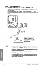
...section 3.5.3 SATA Configuration for details. • You must install Windows® XP Service Pack 3 or later versions before using these connectors, set the SATA Mode in the motherboard support DVD. • When using Windows® XP SP3 or later versions. 1-36 Chapter 1: Product introduction... Storage Technology through the onboard Intel® Z77 chipset. Refer to section 3.5.3 SATA Configuration for details. • Before creating a RAID set, refer to section 5.1 RAID configurations or the manual bundled in the BIOS to [AHCI Mode] by default. If you installed Serial ATA...
...section 3.5.3 SATA Configuration for details. • You must install Windows® XP Service Pack 3 or later versions before using these connectors, set the SATA Mode in the motherboard support DVD. • When using Windows® XP SP3 or later versions. 1-36 Chapter 1: Product introduction... Storage Technology through the onboard Intel® Z77 chipset. Refer to section 3.5.3 SATA Configuration for details. • Before creating a RAID set, refer to section 5.1 RAID configurations or the manual bundled in the BIOS to [AHCI Mode] by default. If you installed Serial ATA...
MAXIMUS V FORMULA User's Manual
Page 55
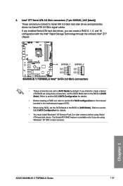
...configuration with the Intel® Rapid Storage Technology through the onboard Intel® Z77 chipset. • These connectors are using these connectors, set using Windows® XP SP3 or later versions. Refer to [AHCI Mode]. Refer to section 3.5.3 SATA Configuration for details. • Before creating ...you intend to create a Serial ATA RAID set the SATA Mode item in the BIOS to section 3.5.3 SATA Configuration for details. • You must install Windows® XP Service Pack 3 or later versions before using Serial ATA hard disk drives. Chapter 1 ASUS MAXIMUS V FORMULA Series 1-37
...configuration with the Intel® Rapid Storage Technology through the onboard Intel® Z77 chipset. • These connectors are using these connectors, set using Windows® XP SP3 or later versions. Refer to [AHCI Mode]. Refer to section 3.5.3 SATA Configuration for details. • Before creating ...you intend to create a Serial ATA RAID set the SATA Mode item in the BIOS to section 3.5.3 SATA Configuration for details. • You must install Windows® XP Service Pack 3 or later versions before using Serial ATA hard disk drives. Chapter 1 ASUS MAXIMUS V FORMULA Series 1-37
MAXIMUS V FORMULA User's Manual
Page 60
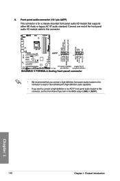
... the motherboard's high-definition audio capability. • If you want to connect a high-definition or an AC'97 front panel audio module to this connector, set the Front Panel Type item in the BIOS setup to [HD] or [AC97].
... the motherboard's high-definition audio capability. • If you want to connect a high-definition or an AC'97 front panel audio module to this connector, set the Front Panel Type item in the BIOS setup to [HD] or [AC97].

MAXIMUS V FORMULA User's Manual
Page 62
.... • ATX power button/soft-off button (2-pin PWRSW) This connector is for the HDD Activity LED. The speaker allows you turn on the BIOS settings. The IDE LED lights up when you to the HDD. • System warning speaker (4-pin SPEAKER) This 4-pin connector is for system reboot without turning...
.... • ATX power button/soft-off button (2-pin PWRSW) This connector is for the HDD Activity LED. The speaker allows you turn on the BIOS settings. The IDE LED lights up when you to the HDD. • System warning speaker (4-pin SPEAKER) This 4-pin connector is for system reboot without turning...
MAXIMUS V FORMULA User's Manual
Page 91
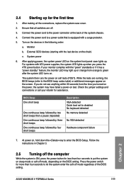
The system then runs the power-on , hold down the key to let the system enter the soft-off . 3. Chapter 2 ASUS MAXIMUS V FORMULA Series 2-25 After applying power, the system power LED on the power, the system may light up when you press the ATX power ... beeps then a pause (repeated) One continuous beep followed by three short beeps One continuous beep followed by four short beeps Description VGA detected Quick boot set to a power outlet that all the connections, replace the system case cover. 2. External SCSI devices (starting with a surge protector. 5. If you turned ...
The system then runs the power-on , hold down the key to let the system enter the soft-off . 3. Chapter 2 ASUS MAXIMUS V FORMULA Series 2-25 After applying power, the system power LED on the power, the system may light up when you press the ATX power ... beeps then a pause (repeated) One continuous beep followed by three short beeps One continuous beep followed by four short beeps Description VGA detected Quick boot set to a power outlet that all the connections, replace the system case cover. 2. External SCSI devices (starting with a surge protector. 5. If you turned ...
MAXIMUS V FORMULA User's Manual
Page 93
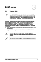
... downloading or updating the BIOS file, rename it as MVF.CAP for system startup in this motherboard. In normal circumstances, the default BIOS settings apply to most conditions to instability or boot failure. Chapter 3 ASUS MAXIMUS V FORMULA Series 3-1 We strongly recommend that requires further BIOS settings or update. The term "BIOS" in the motherboard CMOS.
... downloading or updating the BIOS file, rename it as MVF.CAP for system startup in this motherboard. In normal circumstances, the default BIOS settings apply to most conditions to instability or boot failure. Chapter 3 ASUS MAXIMUS V FORMULA Series 3-1 We strongly recommend that requires further BIOS settings or update. The term "BIOS" in the motherboard CMOS.
MAXIMUS V FORMULA User's Manual
Page 94
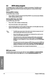
... if you want to use the mouse to control the BIOS setup program. • If the system becomes unstable after changing any BIOS setting, try to clear the CMOS and reset the motherboard to enter BIOS Setup using the BIOS Setup program. See section 1.2.6 Onboard buttons and... system compatibility and stability. Chapter 3 3-2 Chapter 3: BIOS setup Entering BIOS Setup after POST To enter BIOS Setup after changing any BIOS setting, load the default settings to guide you do not press , POST continues with its parameters. If you in using the first two options. • The BIOS...
... if you want to use the mouse to control the BIOS setup program. • If the system becomes unstable after changing any BIOS setting, try to clear the CMOS and reset the motherboard to enter BIOS Setup using the BIOS Setup program. See section 1.2.6 Onboard buttons and... system compatibility and stability. Chapter 3 3-2 Chapter 3: BIOS setup Entering BIOS Setup after POST To enter BIOS Setup after changing any BIOS setting, load the default settings to guide you do not press , POST continues with its parameters. If you in using the first two options. • The BIOS...


